Page 487 of 569
486 Practical hints
Replacing bulbs
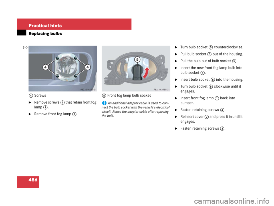
4Screws
�Remove screws4 that retain front fog
lamp 1.
�Remove front fog lamp 1.5Front fog lamp bulb socket
�Turn bulb socket 5 counterclockwise.
�Pull bulb socket 5 out of the housing.
�Pull the bulb out of bulb socket 5.
�Insert the new front fog lamp bulb into
bulb socket 5.
�Insert bulb socket 5 into the housing.
�Turn bulb socket 5 clockwise until it
engages.
�Insert front fog lamp 1 back into
bumper.
�Fasten retaining screws4.
�Reinsert cover 2 and press it in until it
engages.
�Fasten retaining screws3.
iAn additional adapter cable is used to con-
nect the bulb socket with the vehicle’s electrical
circuit. Reuse the adapter cable after replacing
the bulb.
��
Page 489 of 569
 or counterclockwise (right side
trim panel) by 90°")
488 Practical hints
Replacing bulbs
�Insert a suitable object such as a coin
into the slot of lock1.
�Turn lock1 clockwise (left side trim
panel) or counterclockwise (right side
trim panel) by 90° in direction of arrow.
�Remove cover2.
Replacing bulbs
1Tail, side marker, standing, and parking
lamp bulb socket
2Turn signal lamp bulb socket
3Fog lamp bulb socket
(driver’s side only)
4Backup lamp bulb socket
�Depending on which bulb needs to be
replaced, turn the respective bulb
socket 1 - 4 counterclockwise.
�Pull the bulb socket out of the housing.
�Similarly turn the bulb counterclock-
wise carefully and pull the bulb out of
bulb socket.
�Insert the new bulb into the bulb
socket.
�Turn the bulb in the bulb socket clock-
wise carefully.
�Insert the bulb socket into the housing.
�Turn the bulb socket clockwise until it
engages.License plate lamps
1License plate lamp cover
2Screw
�Loosen screws2.
�Remove license plate lamp cover1.
�Replace the license plate lamp bulb.
�Reinstall license plate lamp cover1.
�Retighten screws2.
��
Page 498 of 569
497 Practical hints
Flat tire
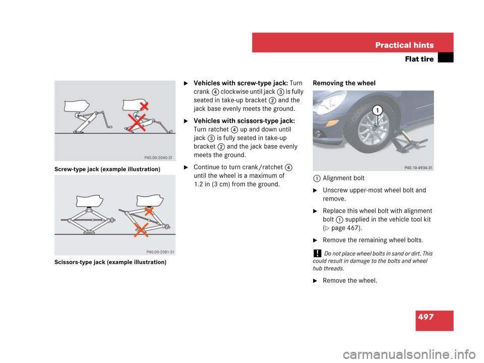
Screw-type jack (example illustration)
Scissors-type jack (example illustration)
�Vehicles with screw-type jack: Turn
crank4 clockwise until jack 3 is fully
seated in take-up bracket2 and the
jack base evenly meets the ground.
�Vehicles with scissors-type jack:
Turn ratchet 4 up and down until
jack3 is fully seated in take-up
bracket2 and the jack base evenly
meets the ground.
�Continue to turn crank/ratchet 4
until the wheel is a maximum of
1.2 in (3 cm) from the ground.Removing the wheel
1Alignment bolt
�Unscrew upper-most wheel bolt and
remove.
�Replace this wheel bolt with alignment
bolt1 supplied in the vehicle tool kit
(
�page 467).
�Remove the remaining wheel bolts.
�Remove the wheel.
!Do not place wheel bolts in sand or dirt. This
could result in damage to the bolts and wheel
hub threads.
Page 502 of 569

501 Practical hints
Flat tire
Lowering the vehicle
�Vehicles with scissors-type jack:
Attach ratchet to vehicle jack in such a
way that the wordDOWN can be seen.
�Lower the vehicle until it is resting fully
on its own weight:
�Vehicles with screw-type jack:
Turn crank counterclockwise.
�Vehicles with scissors-type jack:
Turn ratchet in directionDOWN.
�Remove the jack.1-5Wheel bolts
6Wheel wrench
�Tighten the five wheel bolts evenly,
following the diagonal sequence
illustrated (1to5), until all bolts
are tight. Observe a tightening torque
of 110 lb-ft (150 Nm).
�Store jack and all other vehicle tool kit
items back into the storage well.
Warning!G
Inflate collapsible tire only after the wheel is
properly mounted.
Inflate the collapsible tire using the electric
air pump (
�page 499) before lowering the
vehicle.
Warning!G
Have the tightening torque checked after
changing a wheel. The wheels could come
loose if they are not tightened to a torque of
110 lb-ft (150 Nm).
iThe removed road wheel cannot be stored in
the spare wheel well under the cargo compart-
ment floor, but should be transported in the
cargo compartment wrapped in a protective
wrap.
Vehicles with TPMS or Advanced TPMS*:
Do not activate the tire inflation pressure moni-
tor until a full size wheel/tire with functioning
sensor has been placed back into service on the
vehicle.
Page 511 of 569
.
�Connect the negative lead to the nega-
tive terminal (
�page 509).
Charging th")
510 Practical hints
Battery
�Connect the positive lead to the posi-
tive terminal and fasten it’s cover
(
�page 509).
�Connect the negative lead to the nega-
tive terminal (
�page 509).
Charging the battery
If the battery is discharged, the battery can
be charged using the jump-start contacts
located in the engine compartment
(
�page 512).
�Charge the battery in accordance with
the instructions of the battery charger
manufacturer.
Batteries contain materials that can harm
the environment if disposed of improperly.
Large 12-volt storage batteries contain
lead. Recycling of batteries is the preferred
method of disposal. Many states require
sellers of batteries to accept old batteries
for recycling.
!Never invert the terminal connections!
iThe following procedures must be carried
out following any interruption of battery power
(e.g. due to disconnection):
�Set the clock (�page 176).
Vehicles with COMAND system with naviga-
tion module*: Time and date are set auto-
matically.
�Synchronize the door windows
(
�page 244).
�Synchronize the power tilt/sliding sunroof*
(
�page 250).
�Synchronize the power tilt/sliding panel*
(
�page 255).
�Synchronize the power folding exterior rear
view mirrors* (
�page 204).
Warning!G
Never charge a battery while still installed in
the vehicle unless the accessory battery
charge unit approved by Mercedes-Benz is
being used. Gases may escape during charg-
ing and cause explosions that may result in
paint damage, corrosion or personal injury.
An accessory battery charge unit specially
adapted for Mercedes-Benz vehicles and
tested and approved by Mercedes-Benz is
available, permitting the charging of the
battery in its installed position. Contact an
authorized Mercedes-Benz Light Truck
Center for information and availability.
Charge battery in accordance with the
separate instructions for the accessory
battery charger.
��
Page 517 of 569
516 Practical hints
Towing the vehicle
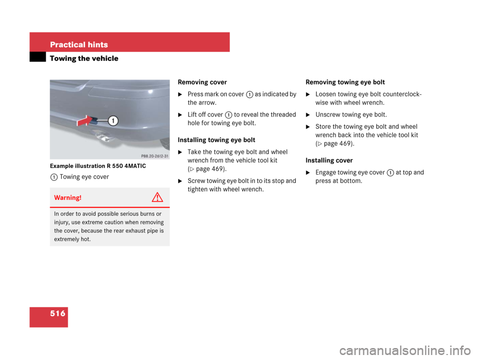
Example illustration R 550 4MATIC
1Towing eye coverRemoving cover
�Press mark on cover1 as indicated by
the arrow.
�Lift off cover1 to reveal the threaded
hole for towing eye bolt.
Installing towing eye bolt
�Take the towing eye bolt and wheel
wrench from the vehicle tool kit
(
�page 469).
�Screw towing eye bolt in to its stop and
tighten with wheel wrench.Removing towing eye bolt
�Loosen towing eye bolt counterclock-
wise with wheel wrench.
�Unscrew towing eye bolt.
�Store the towing eye bolt and wheel
wrench back into the vehicle tool kit
(
�page 469).
Installing cover
�Engage towing eye cover1 at top and
press at bottom.
Warning!G
In order to avoid possible serious burns or
injury, use extreme caution when removing
the cover, because the rear exhaust pipe is
extremely hot.
Page 549 of 569

548 Index
Climate control 208
Air conditioning, Cooling 219
Air conditioning refrigerant 538
Air distribution 213
Air recirculation mode 216
Air vents, Front 208, 214
Air vents, Rear 220
Air volume 214
Control panel, Front 210
Control panel, Rear 220
Deactivating system 212
Defogging 216
Defrosting 214
Rear passenger compartment 220
Residual heat utilization (REST) 219
Clock 26, 176
Cockpit 24
Cold tire inflation pressure 394
Collapsible tire 471, 532
Collapsible wheel chock 471
Combination switch 58, 59, 61, 147
Compass 334
Control system 180Control and operation of radio
transmitters 348
Control system 157
Multifunction display 157
Multifunction steering wheel 158
Resetting to factory default 171
Control system menus 160
AIRMATIC*/Compass 168
AUDIO 165
Distance warning function* 185
Distronic* (Canada only) 168
NAV* 167
Settings 170
Standard display 164
TEL* 187
Trip computer 185
Vehicle status message memory 169
Control system submenus 161, 163
Comfort* 183
Instrument cluster 174
Lighting 177
Time/Date 176
Vehicle 180Coolant 360, 537, 541
Anticorrosion/antifreeze mixing ratio
and quantity 541
Capacities 537
Checking coolant level 360
Messages in the multifunction
display 448–450
Temperature 350
Corner-illuminating front fog lamps* 148
Messages in the multifunction
display 456
Replacing bulbs 480, 481
Cruise control 257
Activating 258
Messages in the multifunction
display 430
Cup holders 308
Front center console 308
Rear center console* 310
Curb weight 394
Customer Assistance Center see CAC
Page 562 of 569

561 Index
Seats 128
Adjusting 43
Easy entry/exit feature 128
Heating* 139
Memory function* 141
Multicontour seat* 132
Ventilation* 140
Securing cargo 290
Selector lever see Gear selector lever
Self-test
Lamps in the instrument cluster 414
OCS 82
Tele Aid* 323
Service and warranty information 10
Service intervals see Maintenance, Service
indicator message 402
Service life
Tires 364
Vehicle battery 503
Service, Parts 522
Service see Maintenance
Service system see Maintenance SystemSettings
AIRMATIC* 276
Clock 176
Comfort functions* 183
Control system menus 160, 162
Control system
submenus 161, 163, 171
Date 176
Distance warning function* 185
Factory, SmartKey 112
Factory, SmartKey with
KEYLESS-GO* 116
Individual, Vehicle 170
Instrument cluster 174
Language, multifunction display 175
Lighting 177
Memory function* 141
Resetting all, Control system 171
Selective, SmartKey 112
Selective, SmartKey with
KEYLESS-GO* 117
Time 176
Vehicle level control* 277Shift program mode, Automatic
transmission 200
Shifting, Automatic transmission 190
Side impact air bags 76
Side marker lamps
Cleaning lenses 407
Messages in the multifunction
display 458
Replacing bulbs 480, 481
Side windows see Power windows
Sidewall 395
SmartKey see Key, SmartKey 110
SmartKey with KEYLESS-GO* see Key,
SmartKey with KEYLESS-GO* 113
Snow chains 399
Snow tires see Winter tires
Spare fuses 467
Spare wheel 471, 532
Inflating 499
Mounting 493
Wheel bolts 467, 498
Speed settings
Cruise control 261
Distronic* (Canada only) 268
Speedometer 27
Spinning see Tires, Direction of rotation
Page:
< prev 1-8 9-16 17-24