2008 MERCEDES-BENZ E-CLASS SALOON key
[x] Cancel search: keyPage 185 of 401

Sliding sunroof
182direction of arrow
2until the sliding/tilt-
ing sunroof is closed.
The sliding/tilting sunroof is closed with
more force.
If the sliding/tilting sunroof locks up during
closing again:
X Immediately after it locks up, pull the
switch again to the pressure point in the
direction of arrow 2until the sliding/tilt-
ing sunroof is closed.
The sliding/tilting sunroof is closed without
the anti-entrapment feature.
Raising The sliding/tilting sunroof can be raised at
the rear for ventilation.
X To raise manually: press the switch in the
direction of arrow 3and hold it until the
sliding/tilting sunroof is in the desired posi-
tion.
X To raise fully: briefly press the switch
beyond the pressure point in the direction
of arrow 3and release it.
X To stop: press or pull the switch in any
direction. Lowering and closing X
To lower manually: pull the switch in the
direction of arrow 2and hold it until the
sliding/tilting sunroof is in the desired posi-
tion.
X To lower fully: pull the switch briefly
beyond the pressure point in the direction
of arrow 2and release it.
X To stop: press or pull the switch in any
direction.
Rain closing feature* The sliding/tilting sunroof closes automati-
cally:
R
if it starts to rain
R at extreme outside temperatures
R after 12 hours
R if there is a malfunction in the power supply
The rear of the sliding/tilting sunroof is then
raised in order to ventilate the interior of the
vehicle.
i The sliding/tilting sunroof is opened
slightly again if it is obstructed while being
closed by the rain closing feature. The rain
closing feature is then deactivated. i
The sliding/tilting sunroof does not close
if:
R it is raised at the rear
R it is blocked
R no rain is falling on the windscreen (e.g.
because the vehicle is under a bridge or
in a carport)
Opening and closing the cover The cover functions as a sunblind. When you
open the sliding/tilting sunroof, the cover
moves back with it.
When the sliding/tilting sunroof is closed or
raised at the rear, you can open or close the
cover manually.
Resetting the sliding/tilting sunroof
Reset the sliding/tilting sunroof if it does not
move smoothly, or if the battery was discon-
nected or discharged.
X
Remove the fuse for the sliding/tilting sun-
roof in the main fuse box (Y page 341).
X Reinsert the fuse.
X Make sure that the key is in position 2in
the ignition lock. Controls
* optional
211_AKB; 2; 5, en-GB
mkalafa,
Version: 2.9.4 2008-02-29T16:57:07+01:00 - Seite 182Dateiname: 6515_3416_02_buchblock.pdf; preflight
Page 186 of 401
Sliding sunroof
183
X
Press the switch in the direction of
arrow 3and hold it until the sliding/tilting
sunroof is fully raised at the rear.
X Keep the switch pressed for an additional
second.
X Make sure that the sliding/tilting sunroof
can be opened or closed fully again
(Y page 181).
X If this is not the case, consult a qualified
specialist workshop. Panorama sliding sunroof with roller
sunblind*
Panorama sliding sunroof G
Risk of injury
Make sure that nobody can become trap-
ped when closing the panorama sliding sun-
roof. If danger threatens, release the switch
and push it briefly in any direction to stop
the panorama sliding sunroof. G
Risk of injury
The glass in the panorama sliding sunroof
could break in an accident. If you are not
wearing a seat belt, there is a risk that you could be thrown through the opening in the
event of the vehicle overturning. Therefore,
always wear a seat belt to reduce the risk
of injuries.
! Only open the panorama sliding sunroof
if it is free of snow and ice. Otherwise, mal-
functions may occur.
Do not allow anything to protrude from the
panorama sliding sunroof. The seals could
otherwise be damaged.
i When the panorama sliding sunroof is
open, resonance noises may occur as well
as the usual airflow noises. They are caused
by minor pressure fluctuations in the vehi-
cle interior. Change the position of the pan-
orama sliding sunroof or open a side
window slightly to reduce or eliminate
these noises.
i It is also possible to open and close the
panorama sliding sunroof from the outside
using the "Summer opening" (Y page 109)
and the "Convenience clos-
ing" (Y page 109) features respectively.
i If PRE-SAFE ®
has been activated, the pan-
orama sliding sunroof closes automatically,
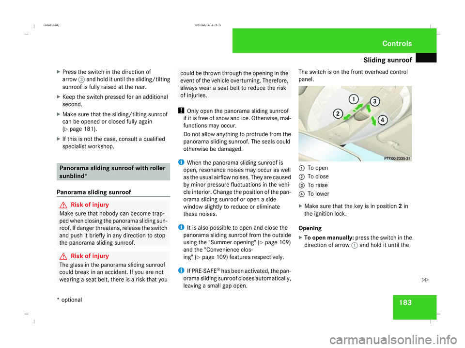
leaving a small gap open. The switch is on the front overhead control
panel.
1
To open
2 To close
3 To raise
4 To lower
X Make sure that the key is in position 2in
the ignition lock.
Opening
X To open manually: press the switch in the
direction of arrow 1and hold it until the Controls
* optional
211_AKB; 2; 5, en-GB
mkalafa,
Version: 2.9.4 2008-02-29T16:57:07+01:00 - Seite 183 ZDateiname: 6515_3416_02_buchblock.pdf; preflight
Page 187 of 401
Sliding sunroof
184panorama sliding sunroof has moved to the
desired position.
X To open fully: press the switch briefly
beyond the pressure point in the direction
of arrow 1and release it.
X To stop: press or pull the switch in any
direction.
Closing
X Press the switch in the direction of arrow
2 and hold it until the panorama sliding
sunroof has moved to the desired position.
Raising
The panorama sliding sunroof can be raised
at the rear for ventilation.
X Press the rear section of the switch in the
direction of arrow 3and hold it until the
panorama sliding sunroof has moved to the
desired position.
Lowering and closing
X Pull the rear section of the switch in the
direction of arrow 4and hold it until the
panorama sliding sunroof has lowered at
the rear and is fully closed. Roller sunblinds The roller sunblinds provide protection from
the sun. The two roller sunblinds can only be
opened and closed together when the pano-
rama sliding sunroof is closed.
G
Risk of injury
Make sure that nobody can become trap-
ped as you open or close the roller sun-
blinds.
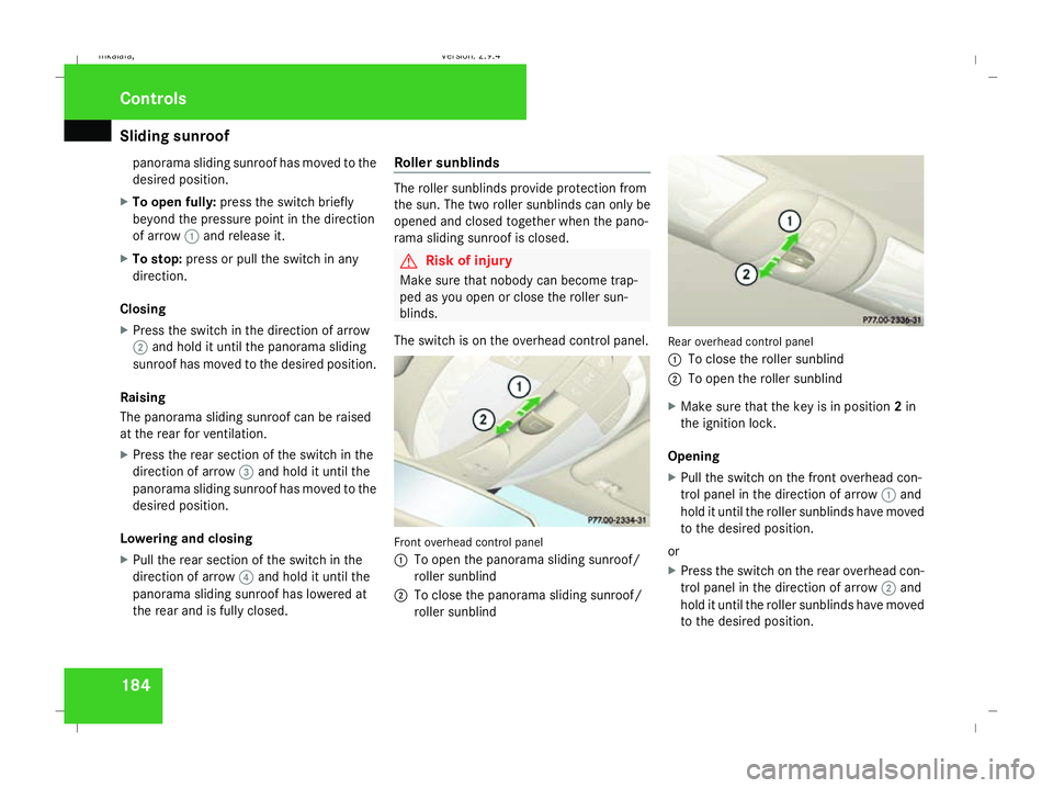
The switch is on the overhead control panel. Front overhead control panel
1
To open the panorama sliding sunroof/
roller sunblind
2 To close the panorama sliding sunroof/
roller sunblind Rear overhead control panel
1
To close the roller sunblind
2 To open the roller sunblind
X Make sure that the key is in position 2in
the ignition lock.
Opening
X Pull the switch on the front overhead con-
trol panel in the direction of arrow 1and
hold it until the roller sunblinds have moved
to the desired position.
or
X Press the switch on the rear overhead con-
trol panel in the direction of arrow 2and
hold it until the roller sunblinds have moved
to the desired position. Controls
211_AKB; 2; 5, en-GB
mkalafa,
Version: 2.9.4 2008-02-29T16:57:07+01:00 - Seite 184Dateiname: 6515_3416_02_buchblock.pdf; preflight
Page 188 of 401
Sliding sunroof
185
To open the roller sunblinds fully, proceed as
follows:
X
Pull the switch on the front overhead con-
trol panel beyond the pressure point in the
direction of arrow 1.
or
X Press the switch on the rear overhead con-
trol panel beyond the pressure point in the
direction of arrow 2.
X To stop: press or pull one of the switches
in any direction.
Closing
X Press the switch on the front overhead con-
trol panel in the direction of arrow 2and
hold it until the roller sunblinds have moved
to the desired position.
or
X Pull the switch on the rear overhead control
panel in the direction of arrow 1and hold
it until the roller sunblinds have moved to
the desired position. Resetting the panorama sliding sunroof
and the roller sunblinds Reset the panorama sliding sunroof and the
roller sunblinds if the panorama sliding sun-
roof does not move smoothly, or if the battery
was disconnected or discharged.
X Remove the fuse for the panorama sliding
sunroof in the main fuse box
(Y page 341).
X Reinsert the fuse.
X Make sure that the key is in position 2in
the ignition lock.
X Close the roller sunblinds fully.
X Keep the switch pressed for an additional
second.
X Open the roller sunblinds fully.
X Keep the switch pressed for an additional
second.
X Raise the panorama sliding sunroof fully.
X Keep the switch pressed for an additional
second.
X Close the panorama sliding sunroof fully.
X Keep the switch pressed for an additional
second. X
Check that the panorama sliding sunroof
can be opened fully again (Y page 183).
X If this is not the case, consult a qualified
specialist workshop. Controls
211_AKB; 2; 5, en-GB
mkalafa,
Version: 2.9.4
2008-02-29T16:57:07+01:00 - Seite 185 ZDateiname: 6515_3416_02_buchblock.pdf; preflight
Page 208 of 401
Loading and stowing
205
Installing the stowage box
X
Fold the two backrests 3forward
(Y page 198).
X Guide stowage box 1into the luggage
compartment through one of the rear doors
with the opening facing towards the front
of the vehicle.
X Press catches 4on stowage box 1into
the gap between backrest 3and the lug-
gage compartment floor.
X Fold backrest 3back (Y page 200).
i Stowage box 1is also held in place from
above by the combined luggage cover and
net.
Loading the stowage box
X Fold backrest 3forward (Y page 198).
X Load stowage box 1through the opening
on the front.
i Stowage box 1in the luggage compart-
ment is closed off by the rear bench seat
and can carry a maximum load of 20 kg.
X Fold backrest 3back (Y page 200). Removing the stowage box
X
Fold double backrest 3forward
(Y page 198).
X Slide stowage box 1with catches 4for-
wards to remove it from the mountings.
X Remove stowage box 1sideways through
a rear door.
X Fold backrest 3back (Y page 200). Stowage compartments
G
Risk of injury
The stowage compartments must be closed
when items are stored in them. Luggage
nets are not designed to secure heavy
items of luggage.
You or other vehicle occupants could be
injured by objects being thrown around if
you:
R brake sharply
R change direction suddenly
R have an accident
Sharp-edged and fragile objects must not
be carried in the luggage net. Do not carry hard objects in the ruffled
pockets. Objects must not protrude over
the top of the ruffled pockets.
i You will find an overview of the stowage
compartments on (Y page 36).
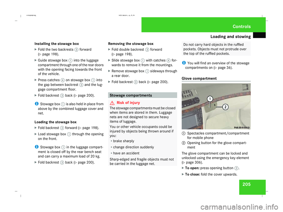
Glove compartment 1
Spectacles compartment/compartment
for mobile phone
2 Opening button for the glove compart-
ment
The glove compartment can be locked and
unlocked using the emergency key element
(Y page 306).
X To open: press opening button 2.
X To close: fold the cover upwards. Controls
211_AKB; 2; 5, en-GB
mkalafa,
Version: 2.9.4 2008-02-29T16:57:07+01:00 - Seite 205 ZDateiname: 6515_3416_02_buchblock.pdf; preflight
Page 213 of 401
Features
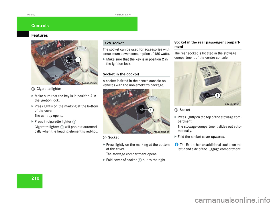
2101
Cigarette lighter
X Make sure that the key is in position 2in
the ignition lock.
X Press lightly on the marking at the bottom
of the cover.
The ashtray opens.
X Press in cigarette lighter 1.
Cigarette lighter 1will pop out automati-
cally when the heating element is red-hot. 12V socket
The socket can be used for accessories with
a maximum power consumption of 180 watts.
X Make sure that the key is in position 2in
the ignition lock.
Socket in the cockpit A socket is fitted in the centre console on
vehicles with the non-smoker's package.
1
Socket
X Press lightly on the marking at the bottom
of the cover.
The stowage compartment opens.
X Fold cover of socket 1out to the right. Socket in the rear passenger compart-
ment The rear socket is located in the stowage
compartment of the centre console.
1
Socket
X Press lightly on the top of the stowage com-
partment.
The stowage compartment slides out auto-
matically.
X Fold the socket cover upwards.
i The Estate has an additional socket on the
left-hand side of the luggage compartment. Controls
211_AKB; 2; 5, en-GB
mkalafa,
Version: 2.9.4 2008-02-29T16:57:07+01:00 - Seite 210Dateiname: 6515_3416_02_buchblock.pdf; preflight
Page 215 of 401
Features
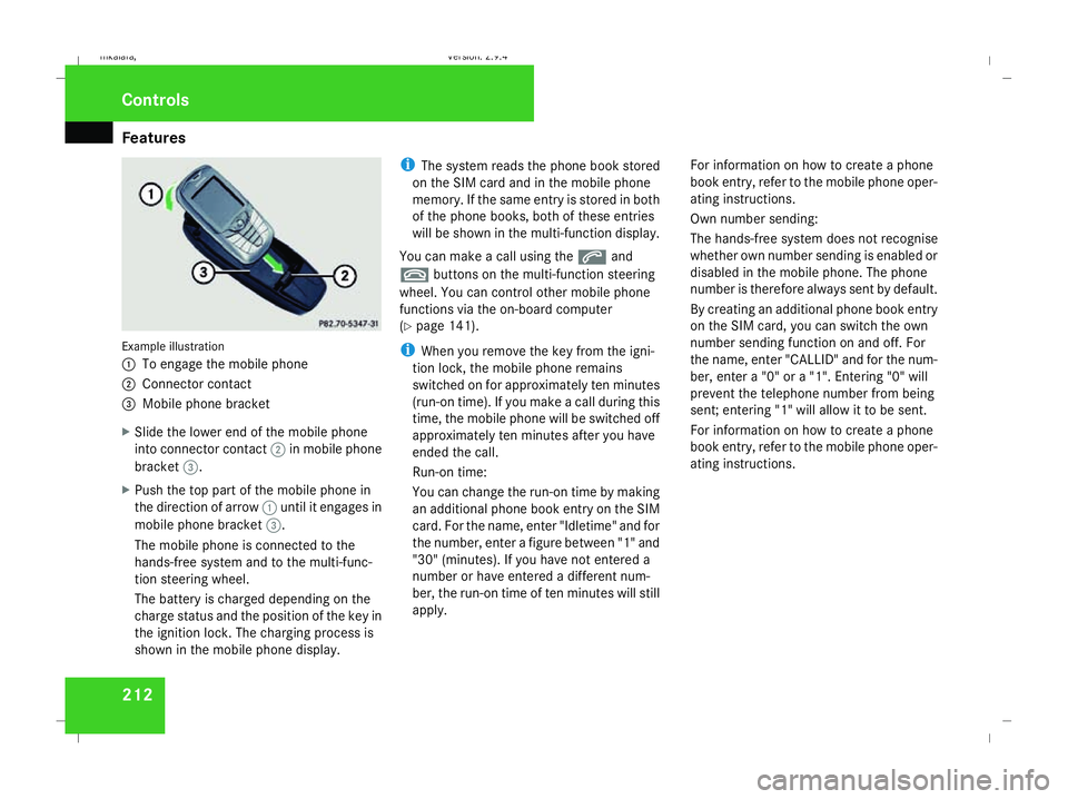
212Example illustration
1
To engage the mobile phone
2 Connector contact
3 Mobile phone bracket
X Slide the lower end of the mobile phone
into connector contact 2in mobile phone
bracket 3.
X Push the top part of the mobile phone in
the direction of arrow 1until it engages in
mobile phone bracket 3.
The mobile phone is connected to the
hands-free system and to the multi-func-
tion steering wheel.
The battery is charged depending on the
charge status and the position of the key in
the ignition lock. The charging process is
shown in the mobile phone display. i
The system reads the phone book stored
on the SIM card and in the mobile phone
memory. If the same entry is stored in both
of the phone books, both of these entries
will be shown in the multi-function display.
You can make a call using the sand
t buttons on the multi-function steering
wheel. You can control other mobile phone
functions via the on-board computer
(Y page 141).
i When you remove the key from the igni-
tion lock, the mobile phone remains
switched on for approximately ten minutes
(run-on time). If you make a call during this
time, the mobile phone will be switched off
approximately ten minutes after you have
ended the call.
Run-on time:
You can change the run-on time by making
an additional phone book entry on the SIM
card. For the name, enter "Idletime" and for
the number, enter a figure between "1" and
"30" (minutes). If you have not entered a
number or have entered a different num-
ber, the run-on time of ten minutes will still
apply. For information on how to create a phone
book entry, refer to the mobile phone oper-
ating instructions.
Own number sending:
The hands-free system does not recognise
whether own number sending is enabled or
disabled in the mobile phone. The phone
number is therefore always sent by default.
By creating an additional phone book entry
on the SIM card, you can switch the own
number sending function on and off. For
the name, enter "CALLID" and for the num-
ber, enter a "0" or a "1". Entering "0" will
prevent the telephone number from being
sent; entering "1" will allow it to be sent.
For information on how to create a phone
book entry, refer to the mobile phone oper-
ating instructions.Controls
211_AKB; 2; 5, en-GB
mkalafa,
Version: 2.9.4 2008-02-29T16:57:07+01:00 - Seite 212Dateiname: 6515_3416_02_buchblock.pdf; preflight
Page 218 of 401

Features
215
X
Erase the memory of the integrated remote
control (Y page 216) before programming
it for the first time.
X Turn the key to position 2in the ignition
lock.
X Press and hold one of transmitter buttons
2 to4 on the integrated remote control.
Indicator lamp 1starts to flash after a
short while. It flashes about once a second.
i Indicator lamp 1flashes immediately
the first time the transmitter button is pro-
grammed. If this transmitter button has
already been programmed, indicator
lamp 1will only start flashing at a rate of
once a second after 20 seconds have
elapsed.
X Keep the transmitter buttons depressed.
X Point the garage door's remote control with
the transmitter towards the left-hand side
of the rear-view mirror from a distance of 5
to 20 cm.
i The distance between the garage door's
remote control and the integrated garage
door opener depends on the system of the
garage door drive. You might require sev-
eral attempts. You should test every posi- tion for at least 20 seconds before trying
another position.
X Keep the transmitter button on the garage
door's remote control depressed until indi-
cator lamp 1starts to flash rapidly.
The programming was successful if indica-
tor lamp 1flashes rapidly.
X Release the transmitter buttons on the
garage door's remote control and the inte-
grated remote control.
If indicator lamp 1goes out after approxi-
mately 20 seconds and did not flash rapidly
before this:
X Release the transmitter buttons on the
integrated and portable remote controls.
X Repeat the programming procedure. At the
same time change the distance between
the garage door's remote control and the
transmitter buttons in the rear-view mirror.
i If the garage door system works with a
rolling code, after programming you must
synchronise the remote control integrated
in the rear-view mirror with the garage door
system receiver.
You will find further information in the
garage door opening system's operating instructions, e.g. the sections on “Synchro-
nising the transmitter” or “Registering a
new transmitter”. You can also call the hot-
line mentioned above.
Opening or closing the garage door Once programmed, the integrated remote
control will assume the function of the garage
door system's remote control. Please read
the operating instructions for the garage door
system.
X
Turn the key to position 2in the ignition
lock.
X Press the transmitter button on the rear-
view mirror that you have programmed to
operate the garage door.
Garage door system with fixed code: indi-
cator lamp 1lights up continuously.
Garage door system with rolling code: indi-
cator lamp 1flashes briefly and then lights
up for approximately two seconds. This is
repeated for up to 20 seconds.
i The transmitter will transmit a signal for
as long as the transmitter button is being
pressed. The transmission will be halted
after a maximum of 20 seconds and indi- Cont
rols
211_AKB; 2; 5, en-GB
mkalafa
,V ersion: 2.9.4
2008-02-29T16:57:07+01:00 - Seite 215 ZDateiname: 6515_3416_02_buchblock.pdf; preflight