2008 MERCEDES-BENZ CLS COUPE folding
[x] Cancel search: foldingPage 10 of 329

7
Temperature display (on-board
computer)
. . . . . . . . . . . . . . . . . . . 116
Topping up . . . . . . . . . . . . . . . . . . . 195
ESP ®
(Electronic Stability Program) . 59
Activating/deactivating . . . . . . . . . . 59
Display message . . . . . . . . . . 222, 231
Warning lamp . . . . . . . . . . . . . . 59, 244
Exterior lighting
Delayed switch-off (on-board
computer) . . . . . . . . . . . . . . . . . . . 126
Exterior mirror parking position
Storing . . . . . . . . . . . . . . . . . . . . 85, 87
Exterior mirrors
Adjusting . . . . . . . . . . . . . . . . . . . . . 84
Anti-dazzle mode (automatic) . . . . . 85
Folding in/out (automatically) . . . . . 84
Folding in/out (electrically) . . . . . . . 84
Folding in when locking (on-board
computer) . . . . . . . . . . . . . . . . . . . 128
Malfunction . . . . . . . . . . . . . . . . . . 260
Parking position . . . . . . . . . . . . . 85, 87
Resetting . . . . . . . . . . . . . . . . . . . . . 84
Storing settings . . . . . . . . . . . . . . . . 86
Exterior view
Overview . . . . . . . . . . . . . . . . . . . . . 20 F
Fire extinguisher
. . . . . . . . . . . . . . . . 217
First-aid kit . . . . . . . . . . . . . . . . . . . . . 216 Flat tyre
MOExtended run-flat system
. . . . . 287
Preparing the vehicle . . . . . . . . . . . 276
TIREFIT kit . . . . . . . . . . . . . . . . . . . 277
Floormat . . . . . . . . . . . . . . . . . . . . . . . 187
Foglamps
Display message . . . . . . . . . . . . . . 235
Fording . . . . . . . . . . . . . . . . . . . . . . . . 208
Frequencies Garage door opener . . . . . . . . . . . . 319
Telephone . . . . . . . . . . . . . . . . . . . 300
Front airbag . . . . . . . . . . . . . . . . . . . . . 46
Front-passenger airbag . . . . . . . . . . . . 46
Fuel . . . . . . . . . . . . . . . . . . . . . . . . . . . 311
Diesel . . . . . . . . . . . . . . . . . . . . . . . 192
Display message . . . . . . . . . . . . . . 231
Loss . . . . . . . . . . . . . . . . . . . . . . . . 253
Petrol . . . . . . . . . . . . . . . . . . . . . . . 191
Fuel consumption . . . . . . . . . . . 312, 313
Fuel filler flap Opening/closing . . . . . . . . . . . . . . 190
Fuel line
Malfunction . . . . . . . . . . . . . . . . . . 253
Fuel tank
Malfunction . . . . . . . . . . . . . . . . . . 253
Range (on-board computer) . . . . . . 130
Fuse allocation chart . . . . . . . . . . . . 295
Fuse box Boot . . . . . . . . . . . . . . . . . . . . . . . . 296
Dashboard . . . . . . . . . . . . . . . . . . . 296 Fuses
. . . . . . . . . . . . . . . . . . . . . . . . . . 295 G
Garage door Opening/closing
(with the remote
control) . . . . . . . . . . . . . . . . . . . . . 187
Garage door opener . . . . . . . . . . . . . . 186
Clearing the memory . . . . . . . . . . . 187
Frequencies . . . . . . . . . . . . . . . . . . 319
Programming the remote control . . 186
Gear indicator (on-board computer) 116
Gearshift program Manual . . . . . . . . . . . . . . . . . . . . . . 108
Genuine Mercedes-Benz parts . . . . . 298
Glove compartment . . . . . . . . . . . . . . 177
Gross vehicle weight, maximum
permissible . . . . . . . . . . . . . . . . . . . . . 310 H
Headlamp Misting up
. . . . . . . . . . . . . . . . . . . 259
Headlamp mode (automatic) . . . . . . . 92
Headlamps Cleaning . . . . . . . . . . . . . . . . . . . . . 212
Cleaning system . . . . . . . . . . . . . . . . 95
Headlamps delayed switch-off
see Exterior lighting delayed switch-off Index
219_AKB; 2; 4, en-GB
mkalafa,
2007-11-13T09:28:36+01:00 - Seite 7
Page 79 of 329
Seats
76
Head restraint height G
Risk of injury
Make sure that the central area of the head
restraint supports the back of your head at
about eye level. You could seriously injure
your neck if your head is not correctly sup-
ported by the head restraint in the event of
an accident. Never travel without a cor-
rectly adjusted and engaged head restraint. 1
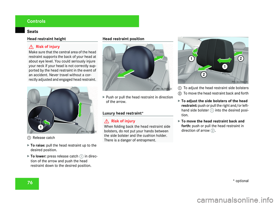
Release catch
X To raise: pull the head restraint up to the
desired position.
X To lower: press release catch 1 in direc-
tion of the arrow and push the head
restraint down to the desired position. Head restraint position
X
Push or pull the head restraint in direction
of the arrow.
Luxury head restraint* G
Risk of injury
When folding back the head restraint side
bolsters, do not put your hands between
the side bolster and the cushion holder.
There is a danger of entrapment. 1
To adjust the head restraint side bolsters
2 To move the head restraint back and forth
X To adjust the side bolsters of the head
restraint: push or pull the right and/or left-
hand side bolster 1 into the desired posi-
tion.
X To move the head restraint back and
forth: push or pull the head restraint in
direction of arrow 2. Controls
* optional
219_AKB; 2; 4, en-GB
mkalafa,
2007-11-13T09:28:36+01:00 - Seite 76
Page 80 of 329
Seats
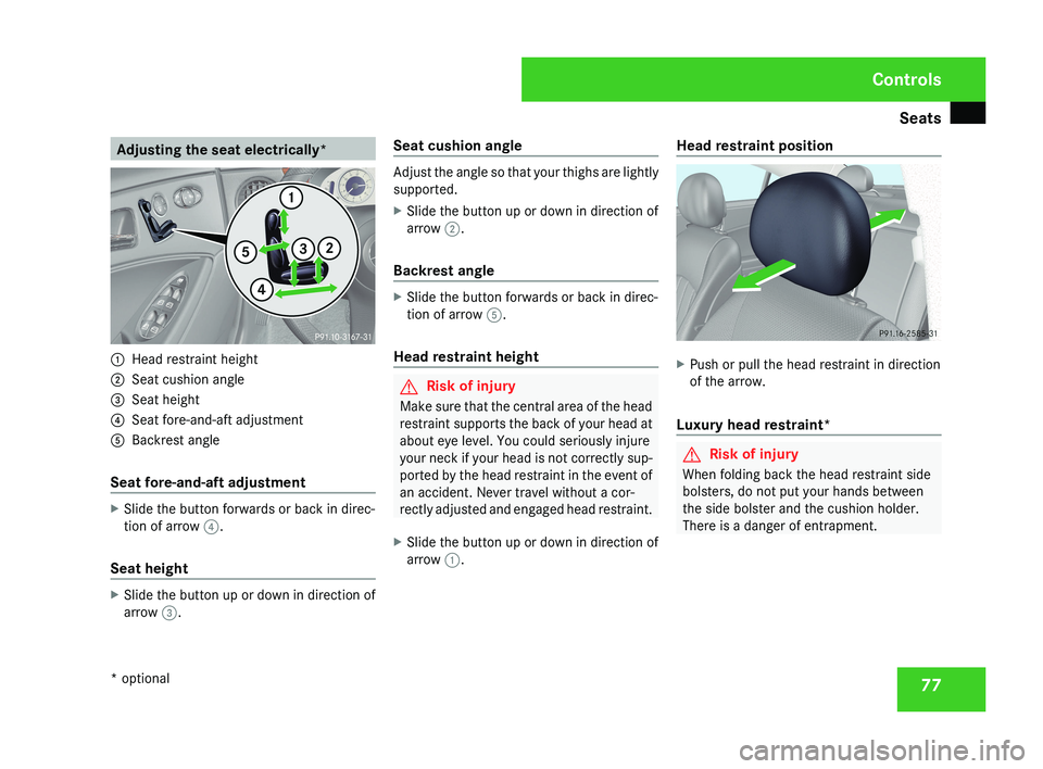
77Adjusting the seat electrically*1
Head restraint height
2 Seat cushion angle
3 Seat height
4 Seat fore-and-aft adjustment
5 Backrest angle
Seat fore-and-aft adjustment
X Slide the button forwards or back in direc-
tion of arrow 4.
Seat height
X Slide the button up or down in direction of
arrow 3. Seat cushion angle
Adjust the angle so that your thighs are lightly
supported.
X
Slide the button up or down in direction of
arrow 2.
Backrest angle
X Slide the button forwards or back in direc-
tion of arrow 5.
Head restraint height
G Risk of injury
Make sure that the central area of the head
restraint supports the back of your head at
about eye level. You could seriously injure
your neck if your head is not correctly sup-
ported by the head restraint in the event of
an accident. Never travel without a cor-
rectly adjusted and engaged head restraint.
X Slide the button up or down in direction of
arrow 1. Head restraint position
X
Push or pull the head restraint in direction
of the arrow.
Luxury head restraint*
G Risk of injury
When folding back the head restraint side
bolsters, do not put your hands between
the side bolster and the cushion holder.
There is a danger of entrapment.
Controls
* optional
219_AKB; 2; 4, en-GB
mkalafa,
2007-11-13T09:28:36+01:00 - Seite 77
Page 81 of 329
Seats
781
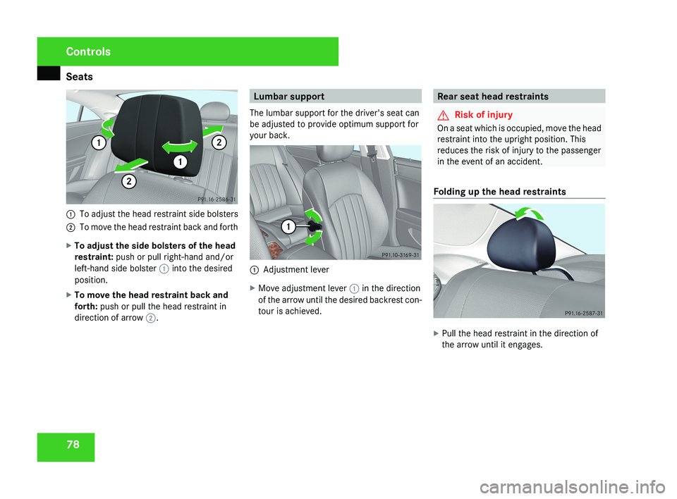
To adjust the head restraint side bolsters
2 To move the head restraint back and forth
X To adjust the side bolsters of the head
restraint: push or pull right-hand and/or
left-hand side bolster 1 into the desired
position.
X To move the head restraint back and
forth: push or pull the head restraint in
direction of arrow 2.
Lumbar support
The lumbar support for the driver's seat can
be adjusted to provide optimum support for
your back.
1 Adjustment lever
X Move adjustment lever 1 in the direction
of the arrow until the desired backrest con-
tour is achieved.
Rear seat head restraints
G Risk of injury
On a seat which is occupied, move the head
restraint into the upright position. This
reduces the risk of injury to the passenger
in the event of an accident.
Folding up the head restraints
X Pull the head restraint in the direction of
the arrow until it engages.
Controls
219_AKB; 2; 4, en-GB
mkalafa,
2007-11-13T09:28:36+01:00 - Seite 78
Page 82 of 329
Seats
79
Folding back the head restraints from
the front
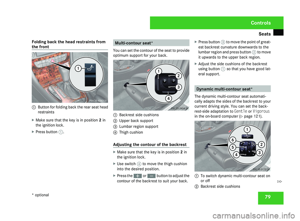
1
Button for folding back the rear seat head
restraints
X Make sure that the key is in position 2 in
the ignition lock.
X Press button 1. Multi-contour seat*
You can set the contour of the seat to provide
optimum support for your back. 1
Backrest side cushions
2 Upper back support
3 Lumbar region support
4 Thigh cushion
Adjusting the contour of the backrest X
Make sure that the key is in position 2 in
the ignition lock.
X Use switch 4 to move the thigh cushion
into the desired position.
X Press the æ or ç button to adjust the
contour of the backrest to suit your back. X
Press button 3 to move the point of great-
est backrest curvature downwards to the
lumbar region and press button 2 to move
it upwards to the upper back region.
X Adjust the side cushions of the backrest
using button 1 so that you have good lat-
eral support. Dynamic multi-contour seat*
The dynamic multi-contour seat automati-
cally adapts the sides of the backrest to your
current driving style. You can set the back-
rest-side adaptation to Gentle or Vigorous
in the on-board computer (Y page 121). 1
To switch dynamic multi-contour seat on
or off
2 Backrest side cushions Controls
* optional
219_AKB; 2; 4, en-GB
mkalafa,
2007-11-13T09:28:36+01:00 - Seite 79 Z
Page 87 of 329
Mirrors
84 Exterior mirrors
G
Risk of accident
The exterior mirrors reduce the size of the
image. Objects are actually closer than
they appear. You could misjudge the dis-
tance from vehicles driving behind and
cause an accident, e.g. when changing
lane. For this reason, make sure of the
actual distance from the vehicle driving
behind by glancing over your shoulder.
The convex exterior mirrors give a larger field
of vision.
At low outside temperatures, the exterior mir-
rors are heated automatically.
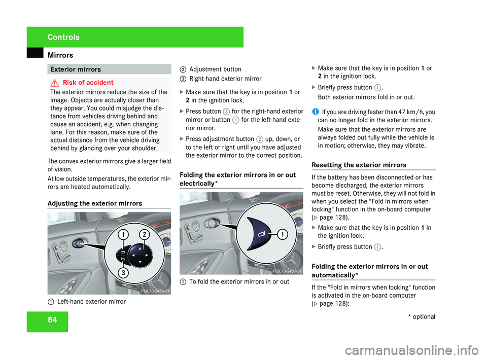
Adjusting the exterior mirrors 1
Left-hand exterior mirror 2
Adjustment button
3 Right-hand exterior mirror
X Make sure that the key is in position 1 or
2 in the ignition lock.
X Press button 3 for the right-hand exterior
mirror or button 1 for the left-hand exte-
rior mirror.
X Press adjustment button 2 up, down, or
to the left or right until you have adjusted
the exterior mirror to the correct position.
Folding the exterior mirrors in or out
electrically* 1
To fold the exterior mirrors in or out X
Make sure that the key is in position 1 or
2 in the ignition lock.
X Briefly press button 1.
Both exterior mirrors fold in or out.
i If you are driving faster than 47 km/h, you
can no longer fold in the exterior mirrors.
Make sure that the exterior mirrors are
always folded out fully while the vehicle is
in motion; otherwise, they may vibrate.
Resetting the exterior mirrors If the battery has been disconnected or has
become discharged, the exterior mirrors
must be reset. Otherwise, they will not fold in
when you select the "Fold in mirrors when
locking" function in the on-board computer
(Y page 128).
X
Make sure that the key is in position 1 in
the ignition lock.
X Briefly press button 1.
Folding the exterior mirrors in or out
automatically* If the "Fold in mirrors when locking" function
is activated in the on-board computer
(Y page 128):Controls
* optional
219_AKB; 2; 4, en-GB
mkalafa,
2007-11-13T09:28:36+01:00 - Seite 84
Page 177 of 329
Loading and stowing
174 Skibag*
G
Risk of injury
The skibag is designed to carry up to four
pairs of skis. Do not use the skibag to carry
any other type of load.
The skibag must always be secured when
laden. Otherwise, injuries could be caused
by it in the event of an accident.
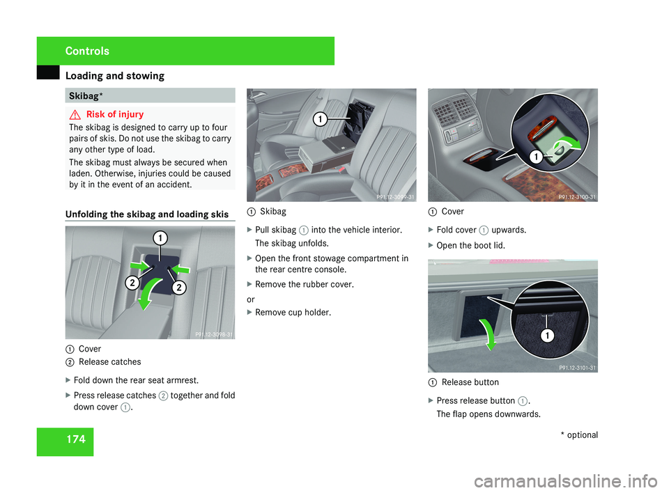
Unfolding the skibag and loading skis 1
Cover
2 Release catches
X Fold down the rear seat armrest.
X Press release catches 2 together and fold
down cover 1. 1
Skibag
X Pull skibag 1 into the vehicle interior.
The skibag unfolds.
X Open the front stowage compartment in
the rear centre console.
X Remove the rubber cover.
or
X Remove cup holder. 1
Cover
X Fold cover 1 upwards.
X Open the boot lid. 1
Release button
X Press release button 1.
The flap opens downwards. Controls
* optional
219_AKB; 2; 4, en-GB
mkalafa,
2007-11-13T09:28:36+01:00 - Seite 174
Page 178 of 329
Loading and stowing
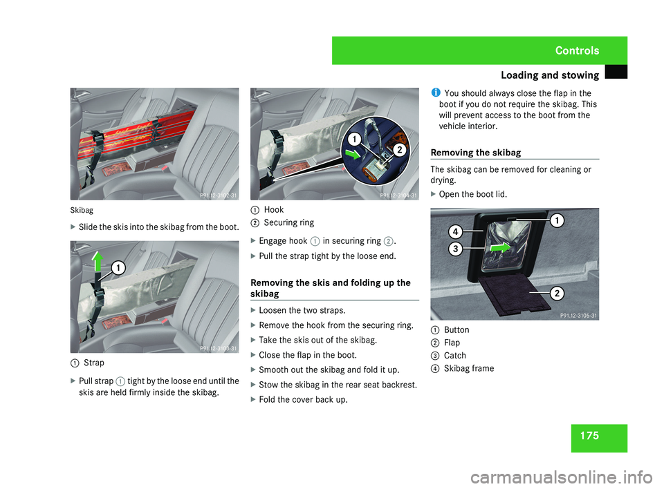
175Skibag
X
Slide the skis into the skibag from the boot.
1 Strap
X Pull strap 1 tight by the loose end until the
skis are held firmly inside the skibag.
1 Hook
2 Securing ring
X Engage hook 1 in securing ring 2.
X Pull the strap tight by the loose end.
Removing the skis and folding up the
skibag
X Loosen the two straps.
X Remove the hook from the securing ring.
X Take the skis out of the skibag.
X Close the flap in the boot.
X Smooth out the skibag and fold it up.
X Stow the skibag in the rear seat backrest.
X Fold the cover back up. i
You should always close the flap in the
boot if you do not require the skibag. This
will prevent access to the boot from the
vehicle interior.
Removing the skibag
The skibag can be removed for cleaning or
drying.
X Open the boot lid.
1 Button
2 Flap
3 Catch
4 Skibag frame
Controls
219_AKB; 2; 4, en-GB
mkalafa,
2007-11-13T09:28:36+01:00 - Seite 175