2008 MERCEDES-BENZ CLS COUPE clock
[x] Cancel search: clockPage 199 of 329
Engine compartment
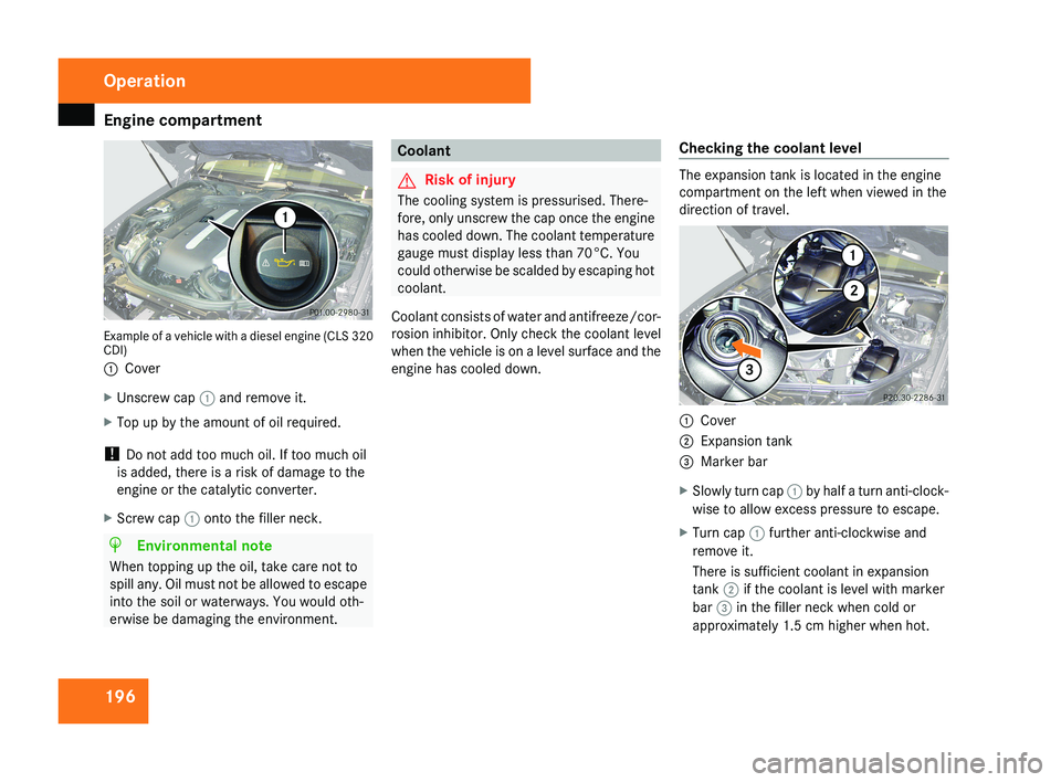
196Example of a vehicle with a diesel engine (CLS 320
CDI)
1
Cover
X Unscrew cap 1 and remove it.
X Top up by the amount of oil required.
! Do not add too much oil. If too much oil
is added, there is a risk of damage to the
engine or the catalytic converter.
X Screw cap 1 onto the filler neck.
H Environmental note
When topping up the oil, take care not to
spill any. Oil must not be allowed to escape
into the soil or waterways. You would oth-
erwise be damaging the environment.
Coolant
G Risk of injury
The cooling system is pressurised. There-
fore, only unscrew the cap once the engine
has cooled down. The coolant temperature
gauge must display less than 70°C. You
could otherwise be scalded by escaping hot
coolant.
Coolant consists of water and antifreeze/cor-
rosion inhibitor. Only check the coolant level
when the vehicle is on a level surface and the
engine has cooled down. Checking the coolant levelThe expansion tank is located in the engine
compartment on the left when viewed in the
direction of travel.
1
Cover
2 Expansion tank
3 Marker bar
X Slowly turn cap 1 by half a turn anti-clock-
wise to allow excess pressure to escape.
X Turn cap 1 further anti-clockwise and
remove it.
There is sufficient coolant in expansion
tank 2 if the coolant is level with marker
bar 3 in the filler neck when cold or
approximately 1.5 cm higher when hot.
Operation
219_AKB; 2; 4, en-GB
mkalafa,
2007-11-13T09:28:36+01:00 - Seite 196
Page 221 of 329
Where will I find...?
218
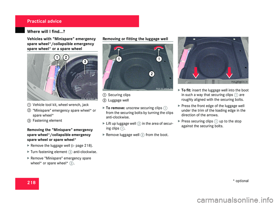
Vehicles with "Minispare" emergency
spare wheel*/collapsible emergency
spare wheel* or a spare wheel
1
Vehicle tool kit, wheel wrench, jack
2 "Minispare" emergency spare wheel* or
spare wheel*
3 Fastening element
Removing the "Minispare" emergency
spare wheel*/collapsible emergency
spare wheel or spare wheel*
X Remove the luggage well (Y page 218).
X Turn fastening element 3 anti-clockwise.
X Remove "Minispare" emergency spare
wheel* or spare wheel* 2.Removing or fitting the luggage well
1
Securing clips
2 Luggage well
X To remove: unscrew securing clips 1
from the securing bolts by turning the clips
anti-clockwise.
X Lift up luggage well 2 in the area of secur-
ing clips 1.
X Remove luggage well 2 from the boot. X
To fit: insert the luggage well into the boot
in such a way that securing clips 1 are
roughly aligned with the securing bolts.
X Press the front edge of the luggage well
under the trim of the loading edge in the
direction of the arrows.
X Press securing clips 1 up to the stop
against the securing bolts. Practical advice
* optional
219_AKB; 2; 4, en-GB
mkalafa,
2007-11-13T09:28:36+01:00 - Seite 218
Page 269 of 329
Locking/unlocking in an emergency
266 Locking/unlocking in an emergency
Emergency key
If the vehicle can no longer be unlocked or
locked with the key or the KEYLESS GO
key*, use the emergency key element.
If you use the emergency key element to
unlock and open the driver's door or the boot
lid, the anti-theft alarm system* will be trig-
gered ( Y page 61).
There are several ways to turn off the alarm:
X Press the k or j button on the key.
or
X Insert the key into the ignition lock.
or
X Press the KEYLESS GO but-
ton* ( Y page 74).
or
X Lock or unlock the vehicle using KEYLESS
GO*. Releasing and removing the emergency
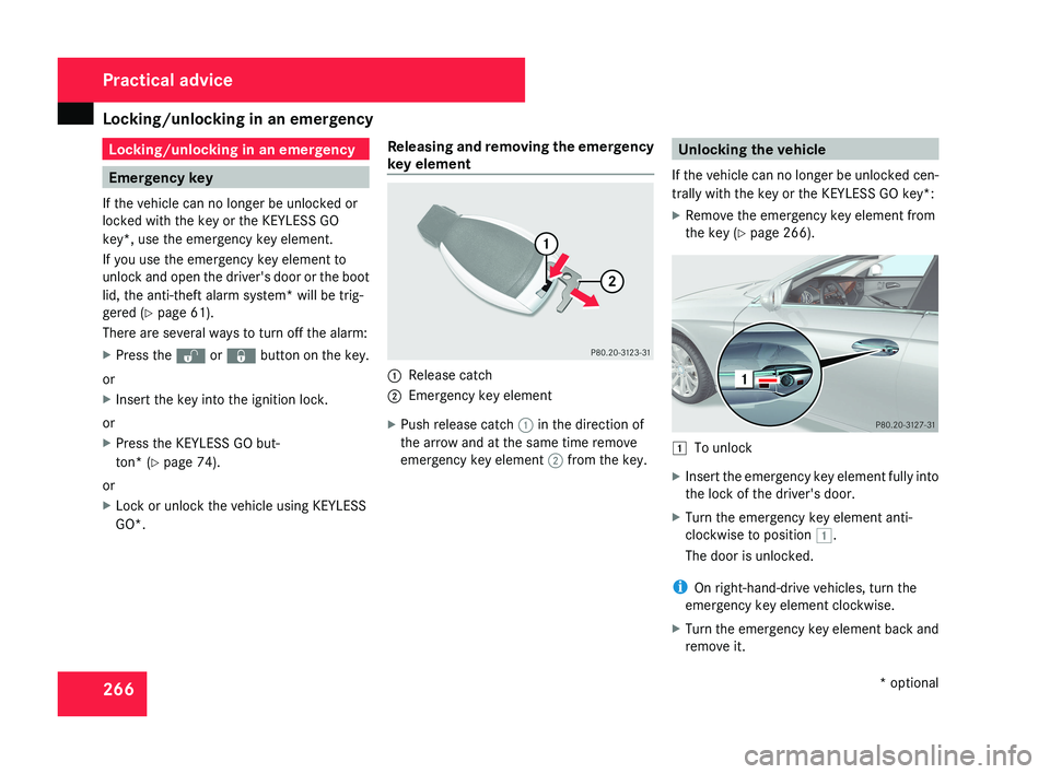
key element 1
Release catch
2 Emergency key element
X Push release catch 1 in the direction of
the arrow and at the same time remove
emergency key element 2 from the key. Unlocking the vehicle
If the vehicle can no longer be unlocked cen-
trally with the key or the KEYLESS GO key*:
X Remove the emergency key element from
the key (Y page 266). $
To unlock
X Insert the emergency key element fully into
the lock of the driver's door.
X Turn the emergency key element anti-
clockwise to position $.
The door is unlocked.
i On right-hand-drive vehicles, turn the
emergency key element clockwise.
X Turn the emergency key element back and
remove it. Practical advice
* optional
219_AKB; 2; 4, en-GB
mkalafa,
2007-11-13T09:28:36+01:00 - Seite 266
Page 270 of 329
Locking/unlocking in an emergency
267Locking the vehicle
If the vehicle can no longer be locked cen-
trally with the key or the KEYLESS GO key*:
X Open the driver's door.
X Close the front-passenger door, the rear
doors and the boot lid.
X Press the central locking button
(Y page 70).
X Check whether the locking knobs on the
doors are still visible. Press the locking
knobs down by hand if necessary.
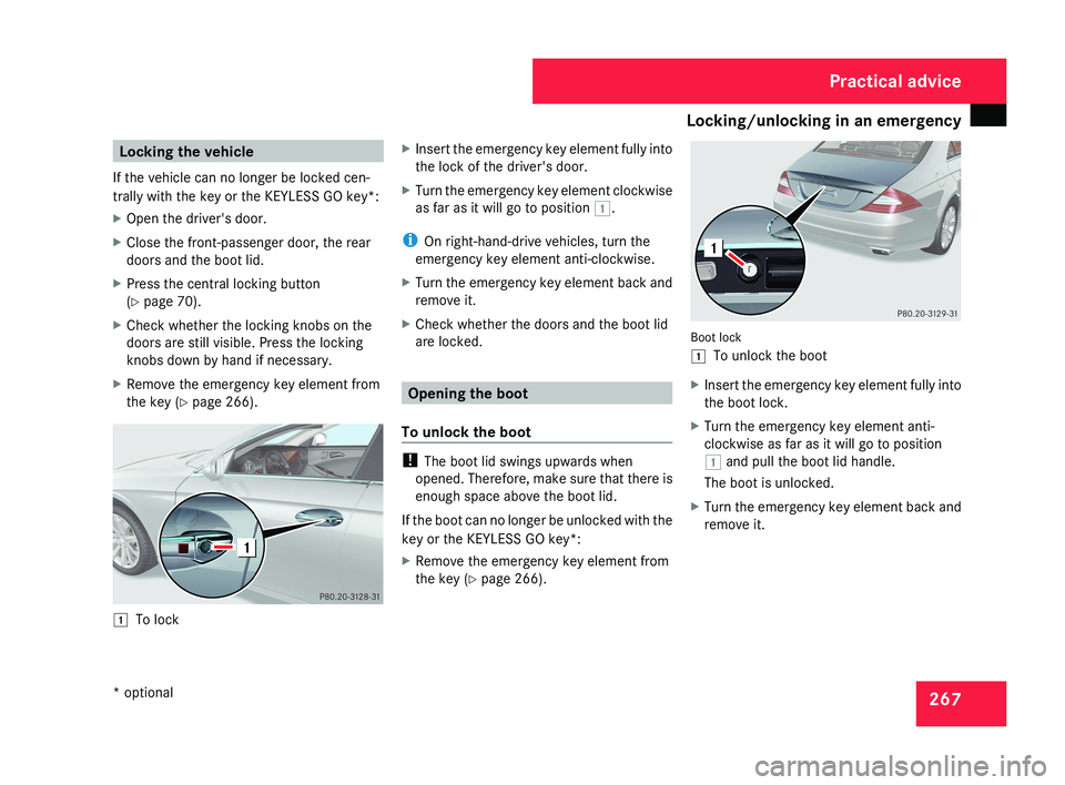
X Remove the emergency key element from
the key (Y page 266).$ To lock X
Insert the emergency key element fully into
the lock of the driver's door.
X Turn the emergency key element clockwise
as far as it will go to position $.
i On right-hand-drive vehicles, turn the
emergency key element anti-clockwise.
X Turn the emergency key element back and
remove it.
X Check whether the doors and the boot lid
are locked.
Opening the boot
To unlock the boot
! The boot lid swings upwards when
opened. Therefore, make sure that there is
enough space above the boot lid.
If the boot can no longer be unlocked with the
key or the KEYLESS GO key*:
X Remove the emergency key element from
the key (Y page 266).
Boot lock
$ To unlock the boot
X Insert the emergency key element fully into
the boot lock.
X Turn the emergency key element anti-
clockwise as far as it will go to position
$ and pull the boot lid handle.
The boot is unlocked.
X Turn the emergency key element back and
remove it.
Practical advice
* optional
219_AKB; 2; 4, en-GB
mkalafa,
2007-11-13T09:28:36+01:00 - Seite 267
Page 276 of 329
Changing the bulbs
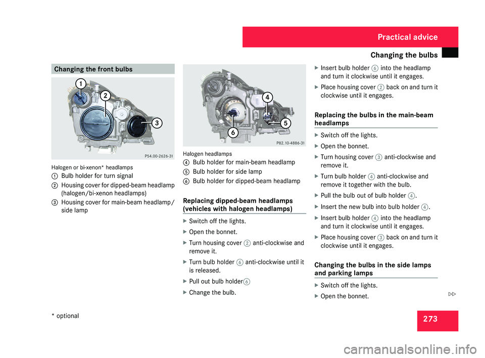
273Changing the front bulbsHalogen or bi-xenon* headlamps
1
Bulb holder for turn signal
2 Housing cover for dipped-beam headlamp
(halogen/bi-xenon headlamps)
3 Housing cover for main-beam headlamp/
side lamp
Halogen headlamps
4Bulb holder for main-beam headlamp
5 Bulb holder for side lamp
6 Bulb holder for dipped-beam headlamp
Replacing dipped-beam headlamps
(vehicles with halogen headlamps)
X Switch off the lights.
X Open the bonnet.
X Turn housing cover 2 anti-clockwise and
remove it.
X Turn bulb holder 6 anti-clockwise until it
is released.
X Pull out bulb holder 6
X Change the bulb. X
Insert bulb holder 6 into the headlamp
and turn it clockwise until it engages.
X Place housing cover 2 back on and turn it
clockwise until it engages.
Replacing the bulbs in the main-beam
headlamps
X Switch off the lights.
X Open the bonnet.
X Turn housing cover 3 anti-clockwise and
remove it.
X Turn bulb holder 4 anti-clockwise and
remove it together with the bulb.
X Pull the bulb out of bulb holder 4.
X Insert the new bulb into bulb holder 4.
X Insert bulb holder 4 into the headlamp
and turn it clockwise until it engages.
X Place housing cover 3 back on and turn it
clockwise until it engages.
Changing the bulbs in the side lamps
and parking lamps
X Switch off the lights.
X Open the bonnet.
Practical advice
* optional
219_AKB; 2; 4, en-GB
mkalafa,
2007-11-13T09:28:36+01:00 - Seite 273
Z
Page 277 of 329
Changing the bulbs
274
X
Turn housing cover 3 anti-clockwise and
remove it.
X Turn main-beam headlamp bulb holder 4
anti-clockwise until it disengages and then
remove it together with the bulb.
X Turn the bulb anti-clockwise, applying
slight pressure, and remove it from bulb
holder 5.
X Insert the new bulb into bulb holder 5 and
turn it clockwise.
X Pull out bulb holder 5.
X Insert main-beam headlamp bulb
holder 4 into the headlamp and turn it
clockwise until it engages.
X Place housing cover 3 back on and turn it
clockwise until it engages.
Replacing the turn signal lamps X
Switch off the lights.
X Open the bonnet.
X Turn bulb holder 1 anti-clockwise and
remove it along with the bulb.
X Turn the bulb anti-clockwise, applying
slight pressure, and remove it from bulb
holder 1. X
Insert the new bulb into bulb holder 1 and
turn it clockwise.
X Insert bulb holder 1 into the headlamp
and turn it clockwise until it engages. Changing the rear bulbs
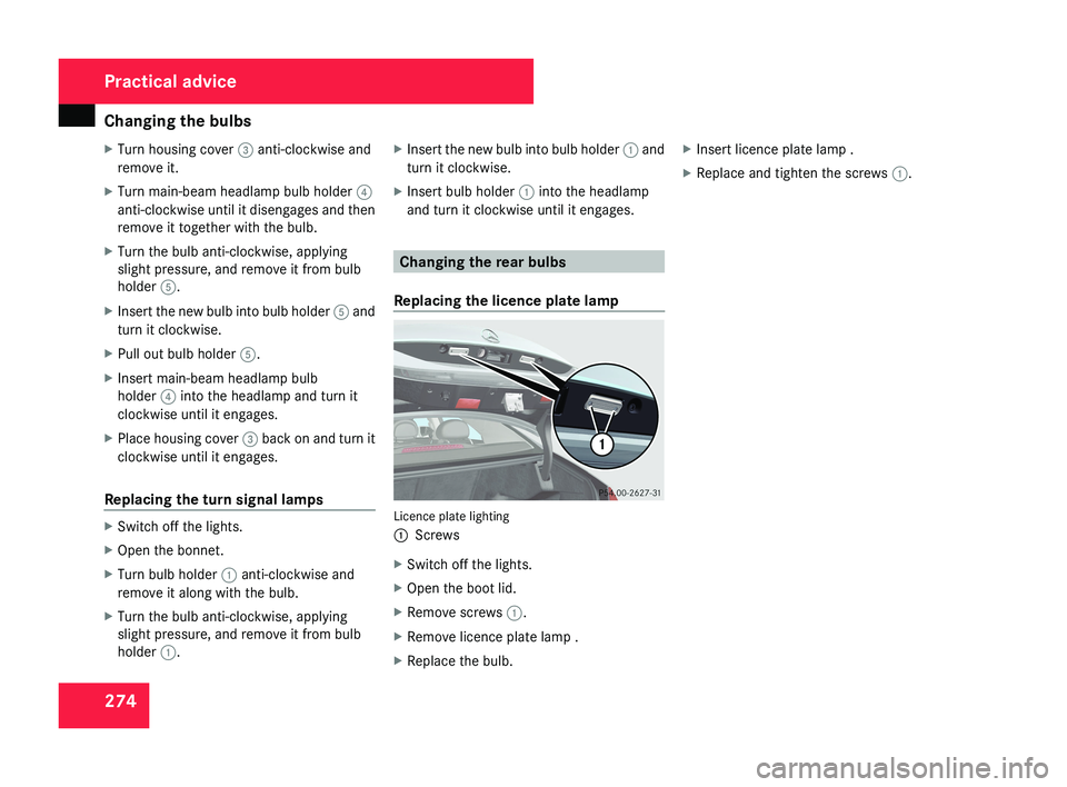
Replacing the licence plate lamp Licence plate lighting
1
Screws
X Switch off the lights.
X Open the boot lid.
X Remove screws 1.
X Remove licence plate lamp .
X Replace the bulb. X
Insert licence plate lamp .
X Replace and tighten the screws 1.Practical advice
219_AKB; 2; 4, en-GB
mkalafa,
2007-11-13T09:28:36+01:00 - Seite 274
Page 289 of 329

Flat tyre
286
X
Screw union nut 5 on air hose 4 onto the
valve.
X Insert plug 3 into the cigarette lighter
socket* ( Y page 181) or into a 12V socket
in your vehicle ( Y page 182).
X Make sure that the key is in position 2 in
the ignition lock.
X Press on/off switch 2 on the electric air
pump to I.
The electric air pump is switched on. The
tyre is inflated.
X When a tyre pressure of 3.5 bar has been
reached, press 0 on the electric air pump
switch.
The electric air pump is switched off.
! Do not operate the electric air pump for
longer than six minutes without a break.
Otherwise, it may overheat.
The air pump can be operated again once
it has cooled down.
If the tyre pressure is higher than 3.5 bar: X
Open the pressure release screw on the
pressure gauge until the tyre pressure is
correct.
X Disconnect the electric air pump and stow
it away.
Lowering the vehicle X
Lower the vehicle. To do this, turn the crank
of the jack anti-clockwise until the vehicle
is standing firmly on the ground again.
X Place the jack to one side. 1
– 5 Wheel bolts
X Tighten the wheel bolts evenly in a cross-
wise pattern in the sequence indica-
ted ( 1 to 5). The tightening torque must
be 130 Nm. G
Risk of accident
Have the tightening torque checked imme-
diately after a wheel is changed. The wheels
could work loose if they are not tightened
to a tightening torque of 130 Nm.
X Turn the jack back to its initial position and
store it and the rest of the vehicle tool kit
in the boot.
Vehicles with the "Minispare"/collapsible
emergency spare wheel*:
X Wrap the faulty wheel in the protective film
provided with the "Minispare"/collapsible
emergency spare wheel* and transport the
wheel in the boot.
or
X Depending on the size of the wheel, the
faulty wheel may also be secured in the
spare wheel recess. In this case, the stow-
age well casing will have to be removed
from the spare wheel well and stowed in the
boot.
i Do not activate the tyre pressure moni-
tor* until the deflated tyre has been
removed from the vehicle. Practical advice
* optional
219_AKB; 2; 4, en-GB
mkalafa,
2007-11-13T09:28:36+01:00 - Seite 286
Page 297 of 329
Towing and tow-starting
294 Fitting the towing eye
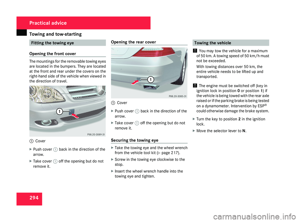
Opening the front cover The mountings for the removable towing eyes
are located in the bumpers. They are located
at the front and rear under the covers on the
right-hand side of the vehicle when viewed in
the direction of travel.
1
Cover
X Push cover 1 back in the direction of the
arrow.
X Take cover 1 off the opening but do not
remove it. Opening the rear cover
1
Cover
X Push cover 1 back in the direction of the
arrow.
X Take cover 1 off the opening but do not
remove it.
Securing the towing eye X
Take the towing eye and the wheel wrench
from the vehicle tool kit ( Y page 217).
X Screw in the towing eye clockwise to the
stop.
X Insert the wheel wrench handle into the
towing eye and tighten. Towing the vehicle
! You may tow the vehicle for a maximum
of 50 km. A towing speed of 50 km/h must
not be exceeded.
With towing distances over 50 km, the
entire vehicle needs to be lifted up and
transported.
! The engine must be switched off (key in
ignition lock in position 0 or position 1) if
the vehicle is being towed with the rear axle
raised or if the parking brake is being tested
on a dynamometer. Intervention by ESP ®
could otherwise damage the brake system.
X Turn the key to position 2 in the ignition
lock.
X Move the selector lever to N. Practical advice
219_AKB; 2; 4, en-GB
mkalafa,
2007-11-13T09:28:36+01:00 - Seite 294