2008 KIA Opirus ECO mode
[x] Cancel search: ECO modePage 164 of 283

433
Driving your vehicle
ESC indicator
(Electronic Stability
Control) (if equipped)
The ESC indicator will illuminate when
the ignition switch is turned ON, but
should go off after approximately 3 sec-
onds. When the ESC is on, it monitors
the driving conditions and under normal
driving conditions, the ESC light will
remain off. When a slippery or low trac-
tion condition is encountered, the ESC
will operate, and the ESC indicator will
blink to indicate the ESC is operating.
ESC OFF indicator
(if equipped)
The ESC OFF indicator will illuminate
when the ignition switch is turned ON,
but should go off after approximately 3
seconds. To switch to ESC OFF mode,
press the ESC OFF button. The ESC
OFF indicator will illuminate indicating
the ESC is deactivated. If this indicator
stays on in the ESC ON mode, the ESC
may have a malfunction. Take your car to
an authorized Kia dealer and have the
system checked.
Safety belt warning chime
If the driver's seat belt is not fastened
when the ignition key is turned “ON” or if
it is disconnected after the key is ON, the
safety belt warning chime will sound for
approximately 6 seconds.
Key reminder warning chime
If the driver’s door is opened and the igni-
tion key is left in the ignition switch in the
LOCK or ACC position, the key reminder
warning chime will sound. This is to pre-
vent you from locking your keys in the
vehicle.
ESCESCOFF
Page 177 of 283

Driving your vehicle
464
Adjusting the driver and passenger side
temperature equally
1. Press the DUAL button again or if youselect the highest (HI) or lowest (Lo)
temperature, the DUAL mode deacti-
vates (the indicator light in the button
turns off). The passenger side temper-
ature will be set to the same tempera-
ture as the driver side.
2. Press the left temperature control but- ton. The driver and passenger side
temperature will be adjusted equally.
Temperature conver sion
If the battery has been discharged or dis-
connected, the temperature mode will
reset as Centigrade degrees.
This is normal condition and you can
switch the temperature mode between
Centigrade to Fahrenheit as follows;
While depressing the MODE button,
depress the DUAL button for 3 seconds
or more. The display will change from
Centigrade to Fahrenheit, or from
Fahrenheit to Centigrade.
Fan speed control button
The fan speed can be set to the desired
speed by turning the appropriate fan
speed control knob.
The higher the fan speed is, the more air
is delivered.
Pressing the “OFF” button turns off the
fan.
Air intake control button
This is used to select outside (fresh) air
position or recirculated air position.
To change the air intake control position,
push the control button.
OGH026062
Page 182 of 283

451
Driving your vehicle
Air conditioning system opera-
tion tips
• If the vehicle has been parked in directsunlight during hot weather, open the
windows for a short time to let the hot
air inside the vehicle escape.
• To help reduce moisture inside of the windows on rainy humid days,
decrease the humidity inside the vehi-
cle by operating the air conditioning
system.
• During air conditioning system opera- tion, you may occasionally notice a
slight change in the engine speed as
the air conditioning compressor cycles
on. This is a normal system operation
characteristics.
• Use the air conditioning system every month only for a few minutes to ensure
maximum system performance.
• When using the air conditioning sys- tem, you may notice clear water drip-
ping (or even pudding) on the ground
under the passenger side of the vehi-
cle. This is a normal system operation
characteristics. • Operating the air conditioning system
in the recirculated air position does
provide maximum cooling, however,
continual operation in this mode may
cause the air inside the vehicle to
become stale.
Checking the amount of air con-
ditioner refrigerant and compres-
sor lubricant
When the amount of refrigerant is low,
the performance of the air conditioning is
reduced. Overfilling also has a bad influ-
ence on the air conditioning system.
Therefore, if abnormal operation is
found, have the system inspected by an
authorized Kia dealer.
CAUTION
When the performance of the air
conditioning system is reduced it is
important that the correct type and amount of oil and refrigerant isu sed. Otherwis e, damage to the
compressor and abnormal system operation may occur.
CAUTION
When us ing the air conditioning
s ystem, monitor the temperature
gauge closely while driving up hill s
or in heavy traffic when out side
temperatures are high. Air condi- tioning system operation may
caus e engine overheating.
Continue to use the blower fan but turn the air conditioning system off
if the temperature gauge indicate s
engine overheating.
WARNING
The air conditioning system should
be serviced by an authorized Kia
dealer. Improper service may cause
serious injury to the per son per-
forming the service.
Page 212 of 283

Driving tips
285
6. Return to the vehicle and firmly pressand release the programmed
HomeLink button up to three times.
The rolling code equipped device
should now recognize the HomeLink
signal and activate when the
HomeLink button is pressed. The
remaining two buttons may now be
programmed if this has not previously
been done. Refer to the
“Programming” portion of this text.Operating HomeLink
To operate, simply press the pro-
grammed HomeLink button. Activation
will now occur for the trained product
(garage door, security system, entry door
lock, estate gate, or home or office light-
ing). For convenience, the hand-held
transmitter of the device may also be
used at any time. The HomeLink
Wireless Controls System (once pro-
grammed) or the original hand-held
transmitter may be used to activate the
device (e.g. garage door, entry door lock,
etc.). In the event that there are still pro-
gramming difficulties, contact HomeLink
at 1-800-355-3515 or on the internet at
www.homelink.com.
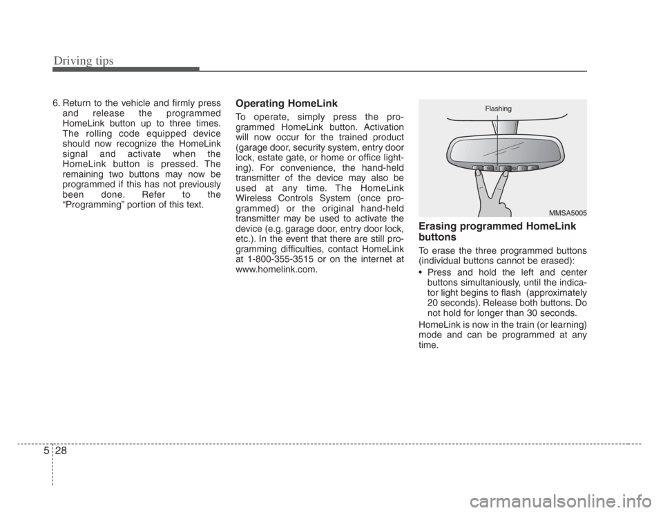
Erasing programmed HomeLink
buttons
To erase the three programmed buttons
(individual buttons cannot be erased):
• Press and hold the left and centerbuttons simultaniously, until the indica-
tor light begins to flash (approximately
20 seconds). Release both buttons. Do
not hold for longer than 30 seconds.
HomeLink is now in the train (or learning)
mode and can be programmed at any
time.
MMSA5005
Flashing
Page 213 of 283

529
Driving tips
Reprogramming a single
HomeLink button
To program a device to HomeLink using
a HomeLink button previously trained,
follow these steps:
1. Press and hold the desired HomeLinkbutton. Do NOT release until step 4
has been completed.
2. When the indicator light begins to flash slowly (after 20 seconds), position the
hand-held transmitter 3~7 cm away
from the HomeLink surface.
3. Press and hold the hand-held trans- mitter button (or press and “cycle” - as
described in “Canadian Programming”
above).
4. The HomeLink indicator light will flash, first slowly and then rapidly. When the
indicator light begins to flash rapidly,
release both buttons.
The previous device has now been
erased and the new device can be acti-
vated by pushing the HomeLink button
that has just been programmed. This pro-
cedure will not affect any other pro-
grammed HomeLink buttons.
Gate operator programming &
canadian programming
During programming, your hand-held
transmitter may automatically stop trans-
mitting. Continue to press and hold the
HomeLink button (note steps 2 through 4
in the “Programming” portion of this text)
while you press and re-press (“cycle”)
your handheld transmitter every two sec-
onds until the frequency signal has been
learned. The indicator light will flash
slowly and then rapidly after several sec-
onds upon successful training.
✽ NOTICE
If programming a garage door opener
or gate, it is advised to unplug the device
during the “cycling” process to prevent
possible motor burn-up.
Accessories
If you would like additional information on
the HomeLink Wireless Control System,
HomeLink compatible products, or to
purchase other accessories such as the
HomeLink® Lighting Package, please
contact HomeLink at 1-800-355-3515 or
on the internet at www.homelink.com.
This device complie s with Industry
Canada Standard RSS-210. Operation
is subject to the following two conditions:
1. This device may not cause interfer- ence, and
2. This device must accept any interfer- ence, including interference that may
cause undesired operation of the
device.
WARNING
Changes or modifications not
expressly approved by the party
responsible for compliance could
void the user’ s authority to operate
the equipment.
IC: 4112104541A Gentex
MODEL/FCC ID: NZLSTDHL3
Page 269 of 283

Maintenance
347
Cold Tire Pressure: The amount of
air pressure in a tire, measured in
kilopascals (kPa) or pounds per
square inch (psi) before a tire has
built up heat from driving.
Curb Weight : This means the weight
of a motor vehicle with standard and
optional equipment including the
maximum capacity of fuel, oil and
coolant, but without passengers and
cargo.
DOT Markings : A code molded into
the sidewall of a tire signifying that
the tire is in compliance with the U.S.
Department of Transportation motor
vehicle safety standards. The DOT
code includes the Tire Identification
Number (TIN), an alphanumeric des-
ignator which can also identify the
tire manufacturer, production plant,
brand and date of production.
GVWR: Gross Vehicle Weight Rating
GAWR FRT: Gross Axle Weight
Rating for the front Axle.
GAWR RR: Gross Axle Weight
Rating for the rear axle. Intended Outboard Sidewall
: The
side of an asymmetrical tire, that
must always face outward when
mounted on a vehicle.
Kilopascal (kPa) : The metric unit for
air pressure.
Load Index : An assigned number
ranging from 1 to 279 that corre-
sponds to the load carrying capacity
of a tire.
Maximum Inflation Pressure : The
maximum air pressure to which a
cold tire may be inflated. The maxi-
mum air pressure is molded onto the
sidewall.
Maximum Load Rating : The load
rating for a tire at the maximum per-
missible inflation pressure for that
tire.
Maximum Loaded Vehicle Weight :
The sum of curb weight; accessory
weight; vehicle capacity weight; and
production options weight.
Normal Occupant Weight:The
number of occupants a vehicle is
designed to seat multiplied by 68 kg
(150 pounds). Occupant Distribution
: Designated
seating positions.
Outward Facing Sidewall: The side
of a asymmetrical tire that has a par-
ticular side that faces outward when
mounted on a vehicle. The outward
facing sidewall bears white lettering
or bears manufacturer, brand, and/or
model name molding that is higher or
deeper than the same moldings on
the inner facing sidewall.
Pa ssenger (P-Metric) Tire : A tire
used on passenger cars and some
light duty trucks and multipurpose
vehicles.
Recommended Inflation Pressure :
Vehicle manufacturer's recommend-
ed tire inflation pressure and shown
on the tire placard.
Radial Ply tire : A pneumatic tire in
which the ply cords that extend to the
beads are laid at 90 degrees to the
centerline of the tread.
Rim: A metal support for a tire and
upon which the tire beads are seat-
ed.
Sidewall: The portion of a tire
between the tread and the bead.
Page 270 of 283

735
Maintenance
Speed Rating: An alphanumeric
code assigned to a tire indicating the
maximum speed at which a tire can
operate.
Traction: The friction between the
tire and the road surface. The
amount of grip provided.
Tread: The portion of a tire that
comes into contact with the road.
Treadwear Indicators: Narrow
bands, sometimes called "wear
bars," that show across the tread of a
tire when only 2/32 inch of tread
remains.
UTQGS: Uniform Tire Quality
Grading Standards, a tire information
system that provides consumers with
ratings for a tire's traction, tempera-
ture and treadwear. Ratings are
determined by tire manufacturers
using government testing proce-
dures. The ratings are molded into
the sidewall of the tire.
Vehicle Capacity Weight : The num-
ber of designated seating positions
multiplied by 68 kg (150 lbs.) plus the
rated cargo and luggage load. Vehicle Maximum Load on the
Tire: Load on an individual tire due to
curb and accessory weight plus
maximum occupant and cargo
weight.
Vehicle Normal Load on the Tire
:
That load on an individual tire that is
determined by distributing to each
axle its share of the curb weight,
accessory weight, and normal occu-
pant weight and driving by 2.
Vehicle Placard : A label permanent-
ly attached to a vehicle showing the
original equipment tire size and rec-
ommended inflation pressure.
All season tires
Kia specifies all season tires on
some models to provide good per-
formance for use all year round,
including snowy and icy road condi-
tions. All season tires are identified
by ALL SEASON and/or M+S (Mud
and Snow) on the tire sidewall. Snow
tires have better snow traction than
all season tires and may be more
appropriate in some areas. Summer tires
Kia specifies summer tires on some
models to provide superior perform-
ance on dry roads. Summer tire per-
formance is substantially reduced in
snow and ice. Summer tires do not
have the tire traction rating M+S
(Mud and Snow) on the tire side wall.
if you plan to operate your vehicle in
snowy or icy conditions. Kia recom-
mends the use of snow tires or all
season tires on all four wheels.
Snow tires
If you equip your car with snow tires,
they should be the same size and
have the same load capacity as the
original tires. Snow tires should be
installed on all four wheels; other-
wise, poor handling may result.
Snow tires should carry 28 kPa (4
psi) more air pressure than the pres-
sure recommended for the standard
tires on the tire label on the driver's
side of the center pillar, or up to the
maximum pressure shown on the tire
sidewall, whichever is less.
Do not drive faster than 120 km/h (75
mph) when your car is equipped with
snow tires.