Page 3771 of 4083
TM-224
< DISASSEMBLY AND ASSEMBLY >
OVERHAUL
VK56DE models for 4WD
16. Bearing race17. Needle bearing18. Manual plate
19. Parking rod 20. Manual shaft oil seal 21. Manual shaft
22. O-ring 23. Band servo anchor end pin 24. Detent spring
25. Spacer 26. Seal ring27. Return spring
28. O-ring 29. Servo assembly30. Snap ring
31. Snap ring 32. Sub-harness33. Control valve with TCM
34. Bracket 35. A/T fluid temperature sensor 2 36. Terminal cord assembly
37. O-ring 38. Retaining pin39. Transmission case
*: Apply Genuine Anaerobic Liquid Gasket or equivalent.
Revision: March 2010 2008 QX56
Page 3773 of 4083
TM-226
< DISASSEMBLY AND ASSEMBLY >
OVERHAUL
19. Manual shaft oil seal20. Manual shaft 21. O-ring
22. Band servo anchor end pin 23. Detent spring 24. Spacer
25. Seal ring 26. Snap ring 27. Return spring
28. O-ring 29. Servo assembly 30. Snap ring
31. Sub-harness 32. Control valve with TCM 33. Bracket
34. A/T fluid temperature sensor 2 35. Terminal cord assembly 36. O-ring
37. Retaining pin 38. Transmission case
Revision: March 2010 2008 QX56
Page 3780 of 4083
DISASSEMBLYTM-233
< DISASSEMBLY AND ASSEMBLY >
CEF
G H
I
J
K L
M A
B
TM
N
O P
5. Remove O-ring from input clutch assembly.
6. Remove oil pump assembly to transmission case bolts.
7. Remove the oil pump assembly evenly from the transmission case using Tools.
CAUTION:
• Fully tighten the sliding hammer screws.
• Make sure that bearing race is installed to the oil pumpassembly edge surface.
8. Remove O-ring from oil pump assembly.
SCIA5011E
SCIA2300E
Tool number : ST25850000 (J-25721-A)
SCIA5474E
SCIA5172E
Revision: March 2010 2008 QX56
Page 3791 of 4083

TM-244
< DISASSEMBLY AND ASSEMBLY >
DISASSEMBLY
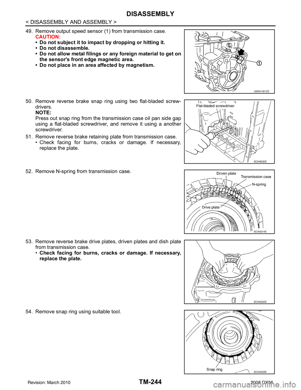
49. Remove output speed sensor (1) from transmission case.
CAUTION:
• Do not subject it to impact by dropping or hitting it.
• Do not disassemble.
• Do not allow metal filings or any foreign material to get on
the sensor's front edge magnetic area.
• Do not place in an area affected by magnetism.
50. Remove reverse brake snap ring using two flat-bladed screw- drivers.
NOTE:
Press out snap ring from the transmission case oil pan side gap
using a flat-bladed screwdriver, and remove it using a another
screwdriver.
51. Remove reverse brake retaining plate from transmission case. • Check facing for burns, cracks or damage. If necessary,
replace the plate.
52. Remove N-spring from transmission case.
53. Remove reverse brake drive plates, driven plates and dish plate from transmission case.
•Check facing for burns, cracks or damage. If necessary,
replace the plate.
54. Remove snap ring using suitable tool.
JSDIA1321ZZ
SCIA5032E
SCIA5214E
SCIA2322E
SCIA2323E
Revision: March 2010 2008 QX56
Page 3792 of 4083
DISASSEMBLYTM-245
< DISASSEMBLY AND ASSEMBLY >
CEF
G H
I
J
K L
M A
B
TM
N
O P
55. Remove spring retainer and return spring from transmission case.
56. Remove seal rings from drum support.
57. Remove needle bearing from drum support edge surface.
58. Remove reverse brake piston from transmission case using compressed air. Refer to TM-227, "
Oil Channel".
CAUTION:
Care should be taken not to ab ruptly blow air. It makes the
piston incline, and as a result , it becomes hard to disas-
semble the pistons.
SCIA2324E
SCIA3333E
SCIA2796E
SCIA5047E
Revision: March 2010 2008 QX56
Page 3794 of 4083
DISASSEMBLYTM-247
< DISASSEMBLY AND ASSEMBLY >
CEF
G H
I
J
K L
M A
B
TM
N
O P
64. Remove manual shaft from transmission case.
65. Remove manual shaft oil seals using suitable tool. CAUTION:
Do not scratch transmission case.
66. Remove detent spring and spacer from transmission case.
67. Remove snap ring from transmission case using suitable tool.
68. Remove servo assembly (with return spring) from transmission case.
SCIA5716E
SCIA2331E
SCIA5248E
SCIA2333E
SCIA5679E
Revision: March 2010 2008 QX56
Page 3816 of 4083
ASSEMBLYTM-269
< DISASSEMBLY AND ASSEMBLY >
CEF
G H
I
J
K L
M A
B
TM
N
O P
ASSEMBLY
Assembly (1)INFOID:0000000004917902
1. Drive manual shaft oil seals into the transmission case until they are flush using suitable tool.
CAUTION:
• Apply ATF to manual shaft oil seals.
• Do not reuse manual shaft oil seals.
2. Install detent spring and spacer in transmission case and secure with the bolt.
3. Install manual shaft to transmission case.
4. Install parking rod to manual plate.
SCIA5259E
Bolt : 7.9 N·m (0.81 kg-m, 70 in-lb)
SCIA5248E
SCIA5716E
SCIA5220E
Revision: March 2010 2008 QX56
Page 3821 of 4083

TM-274
< DISASSEMBLY AND ASSEMBLY >
ASSEMBLY
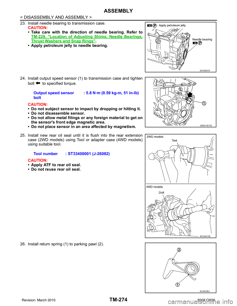
23. Install needle bearing to transmission case.CAUTION:
• Take care with the direction of needle bearing. Refer toTM-229, "
Location of Adjusting Shims, Needle Bearings,
Thrust Washers and Snap Rings".
• Apply petroleum jelly to needle bearing.
24. Install output speed sensor (1) to transmission case and tighten bolt to specified torque.
CAUTION:
• Do not subject sensor to impact by dropping or hitting it.
• Do not disassemble sensor.
• Do not allow metal filings or any foreign material to get on
the sensor's front edge magnetic area.
• Do not place sensor in an area affected by magnetism.
25. Install new rear oil seal until it is flush into the rear extension case (2WD models) using Tool or adapter case (4WD models)
using suitable tool.
CAUTION:
• Apply ATF to rear oil seal.
• Do not reuse rear oil seal.
26. Install return spring (1) to parking pawl (2).
SCIA5031E
Output speed sensor
bolt : 5.8 N·m (0.59 kg-m, 51 in-lb)
JSDIA1321ZZ
Tool number : ST33400001 (J-26082)
WCIA0475E
SCIA6180J
Revision: March 2010
2008 QX56