2008 INFINITI QX56 ESP
[x] Cancel search: ESPPage 1883 of 4083
EM-80
< REMOVAL AND INSTALLATION >
ENGINE ASSEMBLY
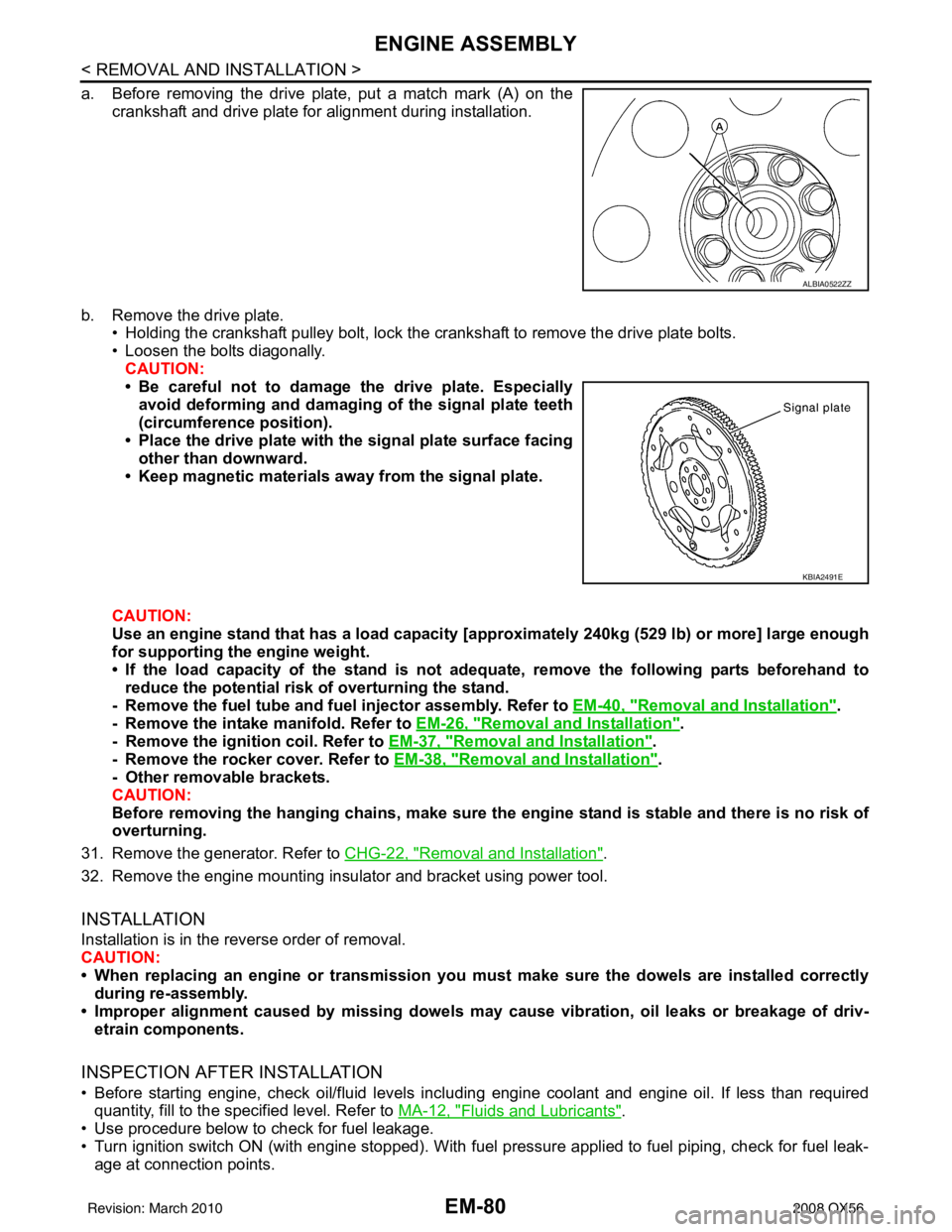
a. Before removing the drive plate, put a match mark (A) on thecrankshaft and drive plate for alignment during installation.
b. Remove the drive plate. • Holding the crankshaft pulley bolt, lock the crankshaft to remove the drive plate bolts.
• Loosen the bolts diagonally.
CAUTION:
• Be careful not to damage the drive plate. Especiallyavoid deforming and damaging of the signal plate teeth
(circumference position).
• Place the drive plate with th e signal plate surface facing
other than downward.
• Keep magnetic materials away from the signal plate.
CAUTION:
Use an engine stand that has a load capacity [a pproximately 240kg (529 lb) or more] large enough
for supporting the engine weight.
• If the load capacity of the stand is not adeq uate, remove the following parts beforehand to
reduce the potential risk of overturning the stand.
- Remove the fuel tube and fuel injector assembly. Refer to EM-40, "
Removal and Installation".
- Remove the intake manifold. Refer to EM-26, "
Removal and Installation".
- Remove the ignition coil. Refer to EM-37, "
Removal and Installation".
- Remove the rocker cover. Refer to EM-38, "
Removal and Installation".
- Other removable brackets.
CAUTION:
Before removing the hanging chains, make sure th e engine stand is stable and there is no risk of
overturning.
31. Remove the generator. Refer to CHG-22, "
Removal and Installation".
32. Remove the engine mounting insulator and bracket using power tool.
INSTALLATION
Installation is in the reverse order of removal.
CAUTION:
• When replacing an engine or transmission you mu st make sure the dowels are installed correctly
during re-assembly.
• Improper alignment caused by mi ssing dowels may cause vibration, oil leaks or breakage of driv-
etrain components.
INSPECTION AFTER INSTALLATION
• Before starting engine, check oil/fluid levels incl uding engine coolant and engine oil. If less than required
quantity, fill to the specified level. Refer to MA-12, "
Fluids and Lubricants".
• Use procedure below to check for fuel leakage.
• Turn ignition switch ON (with engine stopped). With fuel pressure applied to fuel piping, check for fuel leak- age at connection points.
ALBIA0522ZZ
KBIA2491E
Revision: March 2010 2008 QX56
Page 1886 of 4083
ENGINE UNITEM-83
< DISASSEMBLY AND ASSEMBLY >
C
DE
F
G H
I
J
K L
M A
EM
NP
O
DISASSEMBLY
NOTE:
Explained here is how to disassemble with engine stand supporting transmission surface. When using differ-
ent type of engine stand, some steps may be different.
1. Remove engine assembly and mount to engine stand. Refer to
EM-78, "
Removal and Installation".
CAUTION:
Before removing the hanging chains, make sure engi ne stand is stable and there is no risk of over-
turning.
2. Drain engine oil. Refer to LU-9, "
Changing Engine Oil".
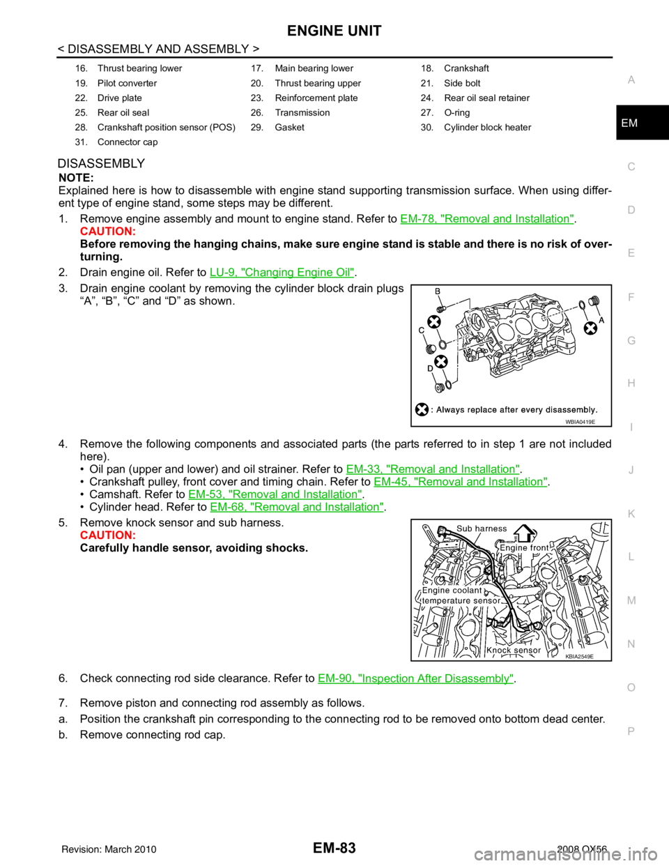
3. Drain engine coolant by removing the cylinder block drain plugs “A”, “B”, “C” and “D” as shown.
4. Remove the following components and associated parts (the parts referred to in step 1 are not included here).
• Oil pan (upper and lower) and oil strainer. Refer to EM-33, "
Removal and Installation".
• Crankshaft pulley, front cover and timing chain. Refer to EM-45, "
Removal and Installation".
• Camshaft. Refer to EM-53, "
Removal and Installation".
• Cylinder head. Refer to EM-68, "
Removal and Installation".
5. Remove knock sensor and sub harness. CAUTION:
Carefully handle sensor, avoiding shocks.
6. Check connecting rod side clearance. Refer to EM-90, "
Inspection After Disassembly".
7. Remove piston and connecting rod assembly as follows.
a. Position the crankshaft pin corresponding to the connecting rod to be removed onto bottom dead center.
b. Remove connecting rod cap.
16. Thrust bearing lower 17. Main bearing lower18. Crankshaft
19. Pilot converter 20. Thrust bearing upper21. Side bolt
22. Drive plate 23. Reinforcement plate24. Rear oil seal retainer
25. Rear oil seal 26. Transmission27. O-ring
28. Crankshaft position sensor (POS) 29. Gasket 30. Cylinder block heater
31. Connector cap
WBIA0419E
KBIA2549E
Revision: March 2010 2008 QX56
Page 1889 of 4083
EM-86
< DISASSEMBLY AND ASSEMBLY >
ENGINE UNIT
ASSEMBLY
1. Fully air-blow the coolant and oil passages in the cylinder block, cylinder bore, and crankcase to removeany foreign material.
CAUTION:
Use goggles to protect your eyes.
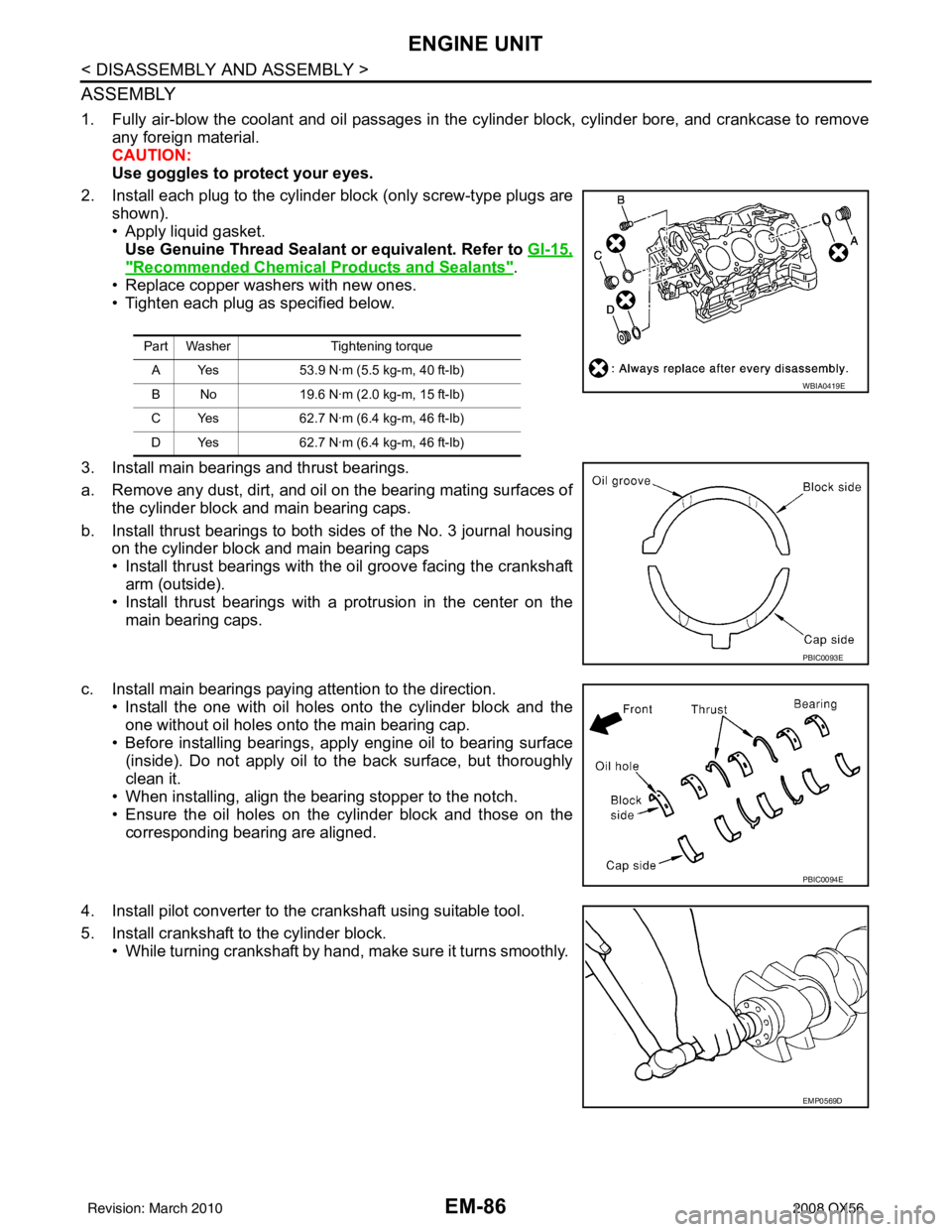
2. Install each plug to the cylinder block (only screw-type plugs are shown).
• Apply liquid gasket. Use Genuine Thread Sealant or equivalent. Refer to GI-15,
"Recommended Chemical Products and Sealants".
• Replace copper washers with new ones.
• Tighten each plug as specified below.
3. Install main bearings and thrust bearings.
a. Remove any dust, dirt, and oil on the bearing mating surfaces of the cylinder block and main bearing caps.
b. Install thrust bearings to both sides of the No. 3 journal housing on the cylinder block and main bearing caps
• Install thrust bearings with the oil groove facing the crankshaft
arm (outside).
• Install thrust bearings with a protrusion in the center on the
main bearing caps.
c. Install main bearings paying attention to the direction. • Install the one with oil holes onto the cylinder block and theone without oil holes onto the main bearing cap.
• Before installing bearings, apply engine oil to bearing surface
(inside). Do not apply oil to the back surface, but thoroughly
clean it.
• When installing, align the bearing stopper to the notch.
• Ensure the oil holes on the cylinder block and those on the
corresponding bearing are aligned.
4. Install pilot converter to the crankshaft using suitable tool.
5. Install crankshaft to the cylinder block. • While turning crankshaft by hand, make sure it turns smoothly.
Part Washer Tightening torque
A Yes 53.9 N·m (5.5 kg-m, 40 ft-lb)
B No 19.6 N·m (2.0 kg-m, 15 ft-lb)
C Yes 62.7 N·m (6.4 kg-m, 46 ft-lb)
D Yes 62.7 N·m (6.4 kg-m, 46 ft-lb)
WBIA0419E
PBIC0093E
PBIC0094E
EMP0569D
Revision: March 2010 2008 QX56
Page 1892 of 4083
ENGINE UNITEM-89
< DISASSEMBLY AND ASSEMBLY >
C
DE
F
G H
I
J
K L
M A
EM
NP
O
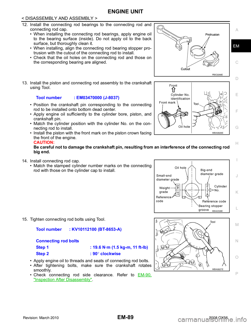
12. Install the connecting rod bearings to the connecting rod and
connecting rod cap.
• When installing the connecting rod bearings, apply engine oilto the bearing surface (inside). Do not apply oil to the back
surface, but thoroughly clean it.
• When installing, align the connecting rod bearing stopper pro-
trusion with the cutout of the connecting rod to install.
• Check that the oil holes on the connecting rod and those on the corresponding bearing are aligned.
13. Install the piston and connecting rod assembly to the crankshaft using Tool.
• Position the crankshaft pin corresponding to the connecting
rod to be installed onto bottom dead center.
• Apply engine oil sufficiently to the cylinder bore, piston, and
crankshaft pin.
• Match the cylinder position with the cylinder No. on the con- necting rod to install.
• Install the piston with the front mark on the piston crown facing the front of the engine.
CAUTION:
Be careful not to damage the crankshaft pin, resu lting from an interference of the connecting rod
big end.
14. Install connecting rod cap. • Match the stamped cylinder number marks on the connectingrod with those on the cylinder cap to install.
15. Tighten connecting rod bolts using Tool. • Apply engine oil to threads and seats of connecting rod bolts.
• After tightening bolts, make sure the crankshaft rotatessmoothly.
• Check connecting rod side clearance. Refer to EM-90,
"Inspection After Disassembly".
PBIC0266E
Tool number : EM03470000 (J-8037)
WBIA0626E
KBIA2536E
Tool number : KV10112100 (BT-8653-A)
Connecting rod bolts
Step 1 : 19.6 N·m (1.5 kg-m, 11 ft-lb)
Step 2: 90° clockwise
WBIA0627E
Revision: March 2010 2008 QX56
Page 1897 of 4083
EM-94
< DISASSEMBLY AND ASSEMBLY >
ENGINE UNIT
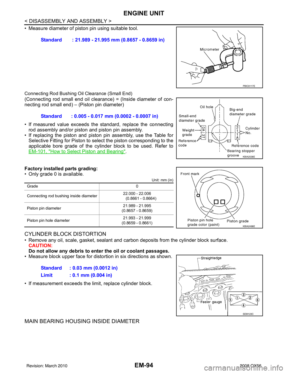
• Measure diameter of piston pin using suitable tool.
Connecting Rod Bushing Oil Clearance (Small End)
(Connecting rod small end oil clearance) = (Inside diameter of con-
necting rod small end) – (Piston pin diameter)
• If measured value exceeds the standard, replace the connectingrod assembly and/or piston and piston pin assembly.
• If replacing the piston and piston pin assembly, use the Table for
Selective Fitting for Piston to select the piston corresponding to the
applicable bore grade of the cylinder block to be used. Refer to
EM-101, "
How to Select Piston and Bearing".
Factory installed parts grading:
• Only grade 0 is available.
Unit: mm (in)
CYLINDER BLOCK DISTORTION
• Remove any oil, scale, gasket, sealant and carbon deposits from the cylinder block surface.
CAUTION:
Do not allow any debris to en ter the oil or coolant passages.
• Measure block upper face for distortion in six directions as shown.
• If measurement exceeds the limit, replace cylinder block.
MAIN BEARING HOUSING INSIDE DIAMETER
Standard : 21.989 - 21.995 mm (0.8657 - 0.8659 in)
PBIC0117E
Standard : 0.005 - 0.017 mm (0.0002 - 0.0007 in)
KBIA2536E
Grade 0
Connecting rod bushing inside diameter 22.000 - 22.006
(0.8661 - 0.8664)
Piston pin diameter 21.989 - 21.995
(0.8657 - 0.8659)
Piston pin hole diameter 21.993 - 21.999
(0.8659 - 0.8661)
KBIA2496E
Standard : 0.03 mm (0.0012 in)
Limit : 0.1 mm (0.004 in)
SEM123C
Revision: March 2010 2008 QX56
Page 1935 of 4083
HEADLAMPEXL-7
< FUNCTION DIAGNOSIS >
C
DE
F
G H
I
J
K
M A
B
EXL
N
O P
FUNCTION DIAGNOSIS
HEADLAMP
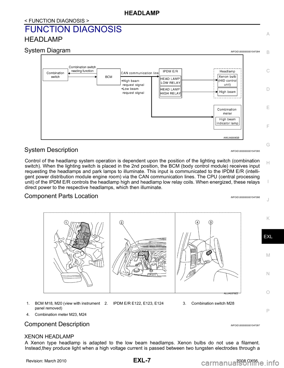
System DiagramINFOID:0000000001547094
System DescriptionINFOID:0000000001547095
Control of the headlamp system operation is dependent upon the position of the lighting switch (combination
switch). When the lighting switch is placed in the 2nd position, the BCM (body control module) receives input
requesting the headlamps and park lamps to illuminate. Th is input is communicated to the IPDM E/R (intelli-
gent power distribution module engine room) via the CA N communication lines. The CPU (central processing
unit) of the IPDM E/R controls the headlamp high and headl amp low relay coils. When energized, these relays
direct power to the respective headlamps, which then illuminate.
Component Parts LocationINFOID:0000000001547096
Component DescriptionINFOID:0000000001547097
XENON HEADLAMP
A Xenon type headlamp is adapted to the low beam headlamps. Xenon bulbs do not use a filament.
Instead,they produce light when a high voltage current is passed between two tungsten electrodes through a
AWLIA0009GB
1. BCM M18, M20 (view with instrument
panel removed) 2. IPDM E/R E122, E123, E124 3. Combination switch M28
4. Combination meter M23, M24
ALLIA0379ZZ
Revision: March 2010 2008 QX56
Page 1944 of 4083
EXL-16
< FUNCTION DIAGNOSIS >
TURN SIGNAL AND HAZARD WARNING LAMPS
TURN SIGNAL AND HAZARD WARNING LAMPS
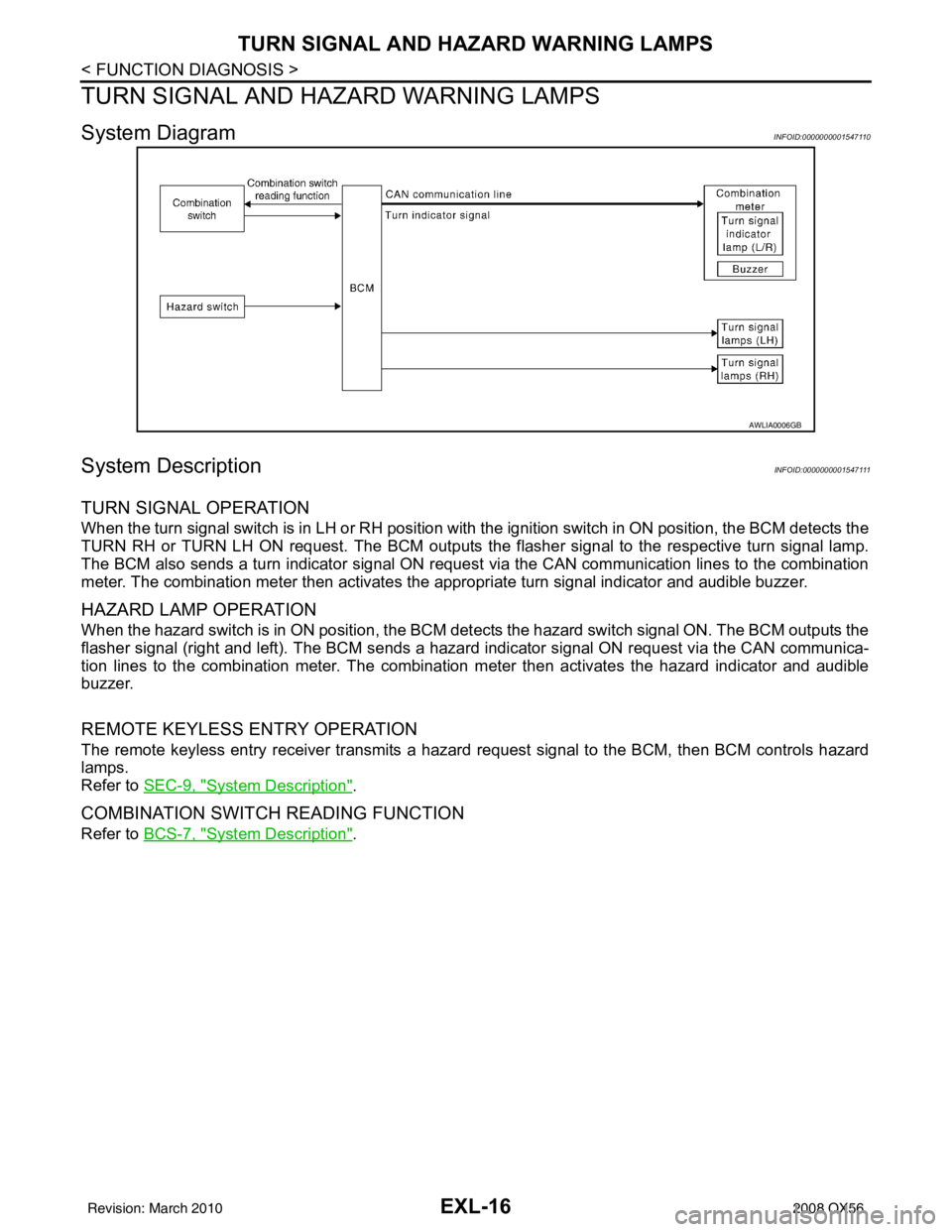
System DiagramINFOID:0000000001547110
System DescriptionINFOID:0000000001547111
TURN SIGNAL OPERATION
When the turn signal switch is in LH or RH position with the ignition switch in ON position, the BCM detects the
TURN RH or TURN LH ON request. The BCM outputs the flasher signal to the respective turn signal lamp.
The BCM also sends a turn indicator signal ON reques t via the CAN communication lines to the combination
meter. The combination meter then activates the appropriate turn signal indicator and audible buzzer.
HAZARD LAMP OPERATION
When the hazard switch is in ON position, the BCM det ects the hazard switch signal ON. The BCM outputs the
flasher signal (right and left). The BCM sends a hazar d indicator signal ON request via the CAN communica-
tion lines to the combination meter. The combination meter then activates the hazard indicator and audible
buzzer.
REMOTE KEYLESS ENTRY OPERATION
The remote keyless entry receiver transmits a hazar d request signal to the BCM, then BCM controls hazard
lamps.
Refer to SEC-9, "
System Description".
COMBINATION SWITCH READING FUNCTION
Refer to BCS-7, "System Description".
AWLIA0006GB
Revision: March 2010 2008 QX56
Page 1948 of 4083
EXL-20
< FUNCTION DIAGNOSIS >
TRAILER TOW
TRAILER TOW
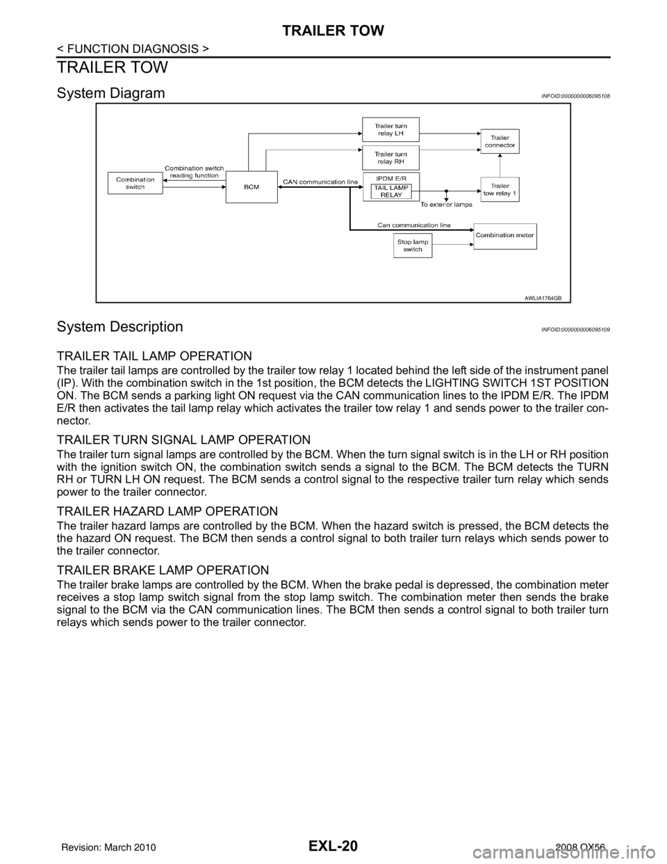
System DiagramINFOID:0000000006095108
System DescriptionINFOID:0000000006095109
TRAILER TAIL LAMP OPERATION
The trailer tail lamps are controlled by the trailer tow relay 1 located behind the left side of the instrument panel
(IP). With the combination switch in the 1st position, the BCM detects the LIGHTING SWITCH 1ST POSITION
ON. The BCM sends a parking light ON request via the CAN communication lines to the IPDM E/R. The IPDM
E/R then activates the tail lamp relay which activates the trailer tow relay 1 and sends power to the trailer con-
nector.
TRAILER TURN SIGNAL LAMP OPERATION
The trailer turn signal lamps are controlled by the BCM. When the turn signal switch is in the LH or RH position
with the ignition switch ON, the combination switch sends a signal to the BCM. The BCM detects the TURN
RH or TURN LH ON request. The BCM sends a control signal to the respective trailer turn relay which sends
power to the trailer connector.
TRAILER HAZARD LAMP OPERATION
The trailer hazard lamps are controlled by the BCM. W hen the hazard switch is pressed, the BCM detects the
the hazard ON request. The BCM then sends a control si gnal to both trailer turn relays which sends power to
the trailer connector.
TRAILER BRAKE LAMP OPERATION
The trailer brake lamps are controlled by the BCM. When the brake pedal is depressed, the combination meter
receives a stop lamp switch signal from the stop lamp switch. The combination meter then sends the brake
signal to the BCM via the CAN communication lines. The BCM then sends a control signal to both trailer turn
relays which sends power to the trailer connector.
AWLIA1764GB
Revision: March 2010 2008 QX56