2008 INFINITI QX56 battery
[x] Cancel search: batteryPage 3069 of 4083

SB-1
RESTRAINTS
C
DE
F
G
I
J
K L
M
SECTION SB
A
B
SB
N
O P
CONTENTS
SEAT BELT
PRECAUTION ....... ........................................2
PRECAUTIONS .............................................. .....2
Precaution for Supplemental Restraint System
(SRS) "AIR BAG" and "SEAT BELT PRE-TEN-
SIONER" ............................................................. ......
2
Precaution Necessary for Steering Wheel Rota-
tion After Battery Disconnect ............................... ......
2
Precaution for Seat Belt Service ...............................3
ON-VEHICLE REPAIR ..................................4
SEAT BELTS .......................................................4
Removal and Installation of Front Seat Belt ........ .....4
Removal and Installation of Second Row Seat Belt
.....
7
Removal and Installation of Third Row Seat Belt .....9
Seat Belt Inspection ............................................. ....11
LATCH (LOWER ANCHORS AND TETHER
FOR CHILDREN) SYSTEM ...............................
14
Removal and Installation .........................................14
TOP TETHER STRAP CHILD RESTRAINT .....15
Removal and Installation .........................................15
Revision: March 2010 2008 QX56
Page 3070 of 4083
SB-2
< PRECAUTION >
PRECAUTIONS
PRECAUTION
PRECAUTIONS
Precaution for Supplemental Restraint System (SRS) "AIR BAG" and "SEAT BELT
PRE-TENSIONER"
INFOID:0000000004886894
The Supplemental Restraint System such as “A IR BAG” and “SEAT BELT PRE-TENSIONER”, used along
with a front seat belt, helps to reduce the risk or severity of injury to the driver and front passenger for certain
types of collision. This system includes seat belt switch inputs and dual stage front air bag modules. The SRS
system uses the seat belt switches to determine the front air bag deployment, and may only deploy one front
air bag, depending on the severity of a collision and w hether the front occupants are belted or unbelted.
Information necessary to service the system safely is included in the SR and SB section of this Service Man-
ual.
WARNING:
• To avoid rendering the SRS inopera tive, which could increase the risk of personal injury or death in
the event of a collision which would result in air bag inflation, all maintenance must be performed by
an authorized NISSAN/INFINITI dealer.
• Improper maintenance, including in correct removal and installation of the SRS, can lead to personal
injury caused by unintent ional activation of the system. For re moval of Spiral Cable and Air Bag
Module, see the SR section.
• Do not use electrical test equipmen t on any circuit related to the SRS unless instructed to in this
Service Manual. SRS wiring harn esses can be identified by yellow and/or orange harnesses or har-
ness connectors.
PRECAUTIONS WHEN USING POWER TOOLS (AIR OR ELECTRIC) AND HAMMERS
WARNING:
• When working near the Airbag Diagnosis Sensor Unit or other Airbag System sensors with the Igni-
tion ON or engine running, DO NOT use air or electri c power tools or strike near the sensor(s) with a
hammer. Heavy vibration could activate the sensor( s) and deploy the air bag(s), possibly causing
serious injury.
• When using air or electric power tools or hammers , always switch the Ignition OFF, disconnect the
battery, and wait at least 3 minu tes before performing any service.
Precaution Necessary for Steering W heel Rotation After Battery Disconnect
INFOID:0000000004886895
NOTE:
• This Procedure is applied only to models with Intelligent Key system and NATS (NISSAN ANTI-THEFT SYS-
TEM).
• Remove and install all control units after disconnecting both battery cables with the ignition knob in the
″LOCK ″ position.
• Always use CONSULT-III to perform self-diagnosis as a part of each function inspection after finishing work.
If DTC is detected, perform trouble diagnosis according to self-diagnostic results.
For models equipped with the Intelligent Key system and NATS, an electrically controlled steering lock mech-
anism is adopted on the key cylinder.
For this reason, if the battery is disconnected or if the battery is discharged, the steering wheel will lock and
steering wheel rotation will become impossible.
If steering wheel rotation is required when battery pow er is interrupted, follow the procedure below before
starting the repair operation.
OPERATION PROCEDURE
1. Connect both battery cables. NOTE:
Supply power using jumper cables if battery is discharged.
2. Use the Intelligent Key or mechanical key to turn the ignition switch to the ″ACC ″ position. At this time, the
steering lock will be released.
3. Disconnect both battery cables. The steering lock will remain released and the steering wheel can be rotated.
4. Perform the necessary repair operation.
Revision: March 2010 2008 QX56
Page 3071 of 4083
PRECAUTIONSSB-3
< PRECAUTION >
C
DE
F
G
I
J
K L
M A
B
SB
N
O P
5. When the repair work is completed, return the ignition switch to the ″LOCK ″ position before connecting
the battery cables. (At this time, the steering lock mechanism will engage.)
6. Perform a self-diagnosis check of al l control units using CONSULT-III.
Precaution for Seat Belt ServiceINFOID:0000000001537286
CAUTION:
• Before removing the seat belt pre-tensioner assembly, turn the ignition switch OFF, disconnect both
battery cables and wait at least 3 minutes.
• After replacing or reinstalling seat belt pre-tensioner assembly, or reconnecting seat belt pre-ten- sioner assembly connector, make sure entire SRS operates properly. Refer to SRC-13, "
SRS Opera-
tion Check".
• Do not disassemble buckle or seat belt assembly.
• Do not reuse seat belt anchor bolts after removal. Replace with new ones.
• Replace anchor bolts if th ey are deformed or worn out.
• Never oil tongue and buckle.
• If any component of seat belt assembly is questio nable, do not repair. Replace the whole seat belt
assembly.
• If webbing is cut, frayed, or damaged, replace seat belt assembly.
• When replacing seat belt assembly, u se a genuine NISSAN seat belt assembly.
AFTER A COLLISION
WARNING:
• Inspect all seat belt assemblies including retractors and attaching hardware after any collision.
• NISSAN recommends that all seat belt assemblies in use during a collision be replaced unless the
collision was minor and the belts show no damage and continue to operate properly. Failure to do so
could result in serious personal injury in an acci dent. Seat belt assemblies not in use during a colli-
sion should also be replaced if either damage or im proper operation is noted. Seat belt pre-tensioner
should be replaced even if the seat belts are not in use during a frontal collision in which the air bags
are deployed.
Replace any seat belt assembly (including anchor bolts) if:
• The seat belt was in use at the time of a collision (except for minor collisions and the belts, retractors and
buckles show no damage and continue to operate properly).
• The seat belt was damaged in an accident. (i.e., torn webbing, bent retractor or guide, etc.)
• The seat belt attaching point was damaged in an accident. Inspect the seat belt attaching area for damage or distortion and repair as necessary before installing a new seat belt assembly.
• Anchor bolts are deformed or worn out.
• The seat belt pre-tensioner should be replaced even if t he seat belts are not in use during the collision in
which the air bags are deployed.
Revision: March 2010 2008 QX56
Page 3073 of 4083
SEAT BELTSSB-5
< ON-VEHICLE REPAIR >
C
DE
F
G
I
J
K L
M A
B
SB
N
O P
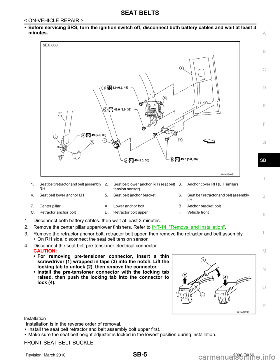
• Before servicing SRS, turn the igni tion switch off, disconnect both battery cables and wait at least 3
minutes.
1. Disconnect both battery cables. then wait at least 3 minutes.
2. Remove the center pillar upper/lower finishers. Refer to INT-14, "
Removal and Installation".
3. Remove the retractor anchor bolt, retractor bolt upper, then remove the retractor and belt assembly. • On RH side, disconnect the seat belt tension sensor.
4. Disconnect the seat belt pre-tensioner electrical connector. CAUTION:
• For removing pre-tensioner connector, insert a thinscrewdriver (1) wrapped in tape (3) into the notch. Lift the
locking tab to unlock (2), then remove the connector.
• Install the pre-tensioner co nnector with the locking tab
raised, then push the locking tab into the connector to
lock (4).
Installation
Installation is in the reverse order of removal.
• Install the seat belt retractor and belt assembly bolt upper first.
• Make sure the seat belt height adjuster is lo cked in the lowest position during installation.
FRONT SEAT BELT BUCKLE
1. Seat belt retractor and belt assembly
RH 2. Seat belt lower anchor RH (seat belt
tension sensor) 3. Anchor cover RH (LH similar)
4. Seat belt lower anchor LH 5. Seat belt anchor bracket6. Seat belt retractor and belt assembly
LH
7. Center pillar A. Lower anchor boltB. Anchor bracket bolt
C. Retractor anchor bolt D. Retractor bolt upper ⇐Vehicle front
WHIA0346E
WHIA0279E
Revision: March 2010 2008 QX56
Page 3074 of 4083
SB-6
< ON-VEHICLE REPAIR >
SEAT BELTS
Removal
1. Disconnect both battery cables, then wait at least 3 minutes.
2. Remove the front seat. Refer to SE-49, "
Removal and Installation".
3. Remove the seat cushion. Refer to SE-71, "
Disassembly and Assembly".
4. Disconnect the seat belt buckle pre-tensioner electrical connector. CAUTION:
• For removing pre-tensioner connector, insert a thinscrewdriver (1) wrapped in tape (3) into the notch. Lift the
locking tab to unlock (2), then remove the connector.
• Install the pre-tensioner connector with the locking tab raised, then push the locking tab into the connector to
lock (4).
5. Remove screw and seat cushion inner finisher.
6. Remove the anchor bolt, then remove front seat belt buckle from the seat frame.
Installation
Installation is in the reverse order of removal.
WHIA0279E
WHIA0280E
Revision: March 2010 2008 QX56
Page 3089 of 4083
SCS-6
< FUNCTION DIAGNOSIS >
SUSPENSION CONTROL SYSTEM
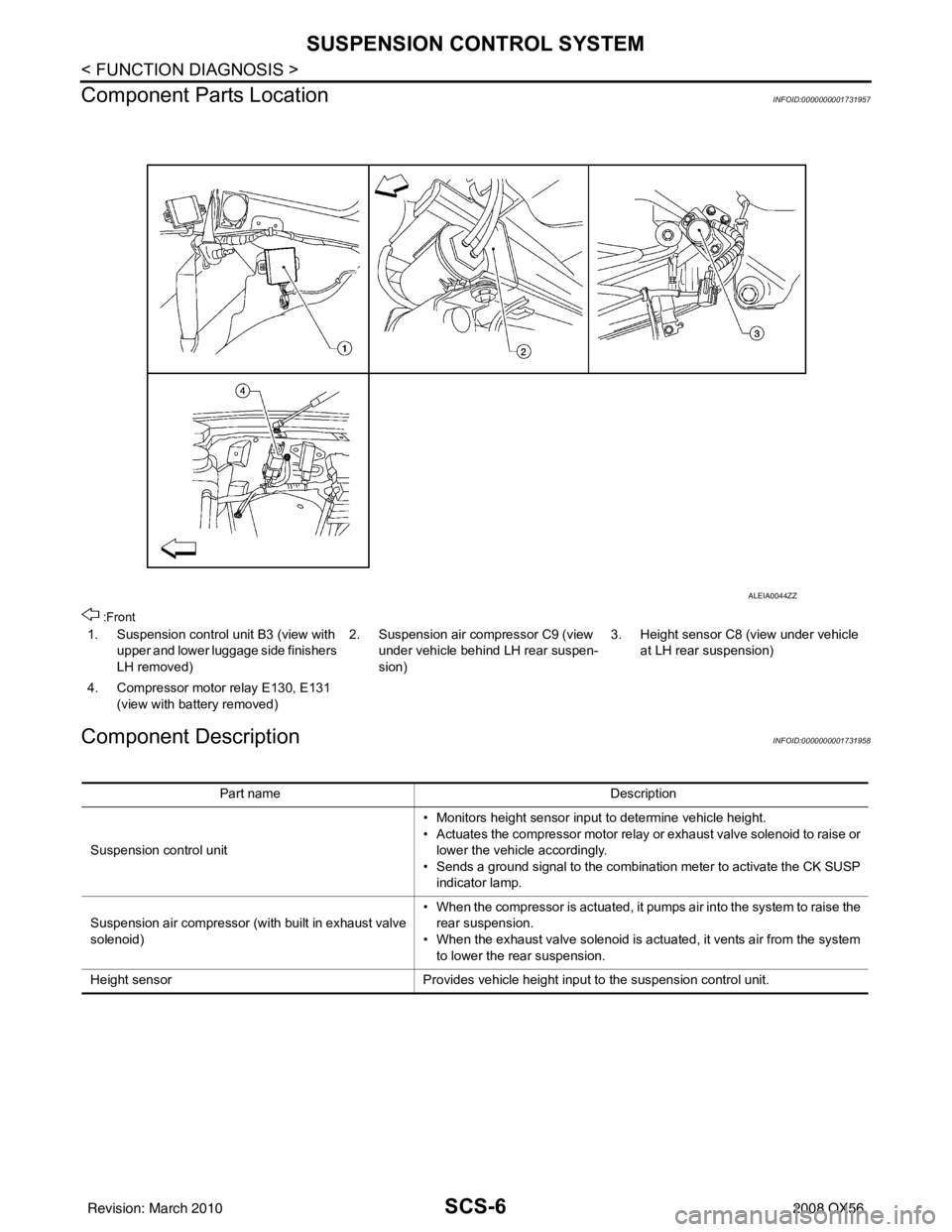
Component Parts Location
INFOID:0000000001731957
:Front
Component DescriptionINFOID:0000000001731958
1. Suspension control unit B3 (view with upper and lower luggage side finishers
LH removed) 2. Suspension air compressor C9 (view
under vehicle behind LH rear suspen-
sion) 3. Height sensor C8 (view under vehicle
at LH rear suspension)
4. Compressor motor relay E130, E131 (view with battery removed)
ALEIA0044ZZ
Part name Description
Suspension control unit • Monitors height sensor input to determine vehicle height.
• Actuates the compressor motor relay or exhaust valve solenoid to raise or
lower the vehicle accordingly.
• Sends a ground signal to the combination meter to activate the CK SUSP indicator lamp.
Suspension air compressor (with built in exhaust valve
solenoid) • When the compressor is actuated, it pumps air into the system to raise the
rear suspension.
• When the exhaust valve solenoid is actuated, it vents air from the system to lower the rear suspension.
Height sensor Provides vehicle height input to the suspension control unit.
Revision: March 2010 2008 QX56
Page 3100 of 4083
POWER SUPPLY AND GROUND CIRCUITSCS-17
< COMPONENT DIAGNOSIS >
C
DF
G H
I
J
K L
M A
B
SCS
N
O P
POWER SUPPLY AND GROUND CIRCUIT
SUSPENSION CONTROL UNIT
SUSPENSION CONTROL UNIT : Diagnosis ProcedureINFOID:0000000001731984
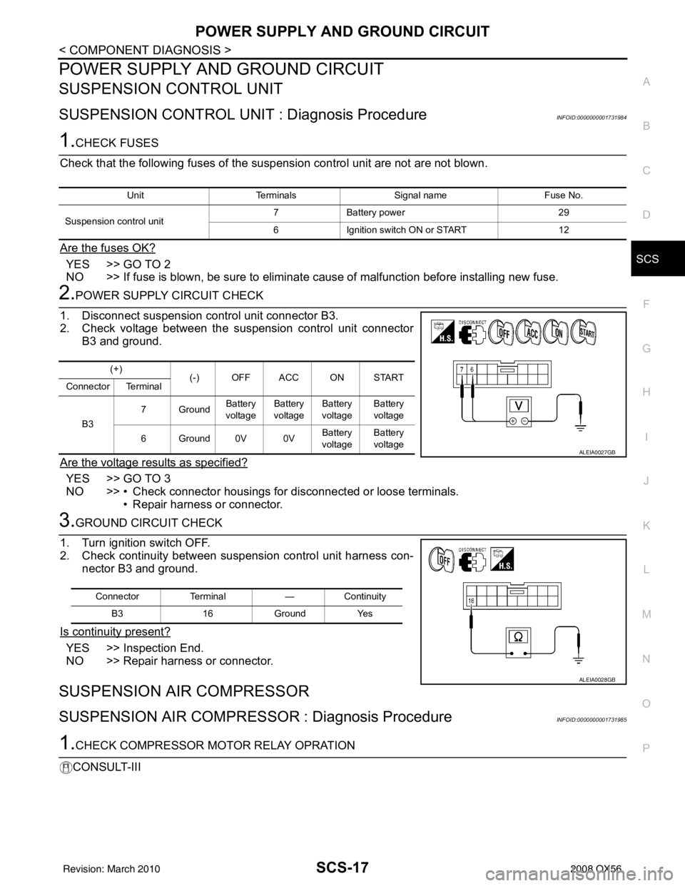
1.CHECK FUSES
Check that the following fuses of the sus pension control unit are not are not blown.
Are the fuses OK?
YES >> GO TO 2
NO >> If fuse is blown, be sure to eliminate cause of malfunction before installing new fuse.
2.POWER SUPPLY CIRCUIT CHECK
1. Disconnect suspension control unit connector B3.
2. Check voltage between the suspension control unit connector B3 and ground.
Are the voltage results as specified?
YES >> GO TO 3
NO >> • Check connector housings for disconnected or loose terminals. • Repair harness or connector.
3.GROUND CIRCUIT CHECK
1. Turn ignition switch OFF.
2. Check continuity between suspension control unit harness con- nector B3 and ground.
Is continuity present?
YES >> Inspection End.
NO >> Repair harness or connector.
SUSPENSION AIR COMPRESSOR
SUSPENSION AIR COMPRESSOR : Diagnosis ProcedureINFOID:0000000001731985
1.CHECK COMPRESSOR MOTOR RELAY OPRATION
CONSULT-III
Unit Terminals Signal name Fuse No.
Suspension control unit 7
Battery power 29
6 Ignition switch ON or START 12
(+)
(-) OFF ACC ON START
Connector Terminal
B3 7Ground
Battery
voltage Battery
voltage Battery
voltage Battery
voltage
6Ground0V 0V Battery
voltage Battery
voltage
ALEIA0027GB
Connector Terminal —Continuity
B3 16Ground Yes
ALEIA0028GB
Revision: March 2010 2008 QX56
Page 3101 of 4083
SCS-18
< COMPONENT DIAGNOSIS >
POWER SUPPLY AND GROUND CIRCUIT
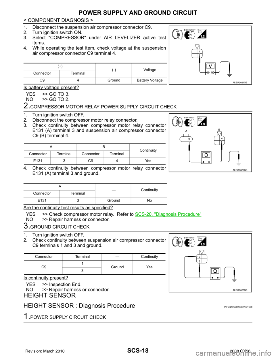
1. Disconnect the suspension air compressor connector C9.
2. Turn ignition switch ON.
3. Select "COMPRESSOR" under AIR LEVELIZER active testitems.
4. While operating the test item, check voltage at the suspension
air compressor connector C9 terminal 4.
Is battery voltage present?
YES >> GO TO 3.
NO >> GO TO 2.
2.COMPRESSOR MOTOR RELAY POWER SUPPLY CIRCUIT CHECK
1. Turn ignition switch OFF.
2. Disconnect the compressor motor relay connector.
3. Check continuity between compressor motor relay connector E131 (A) terminal 3 and suspension air compressor connector
C9 (B) terminal 4.
4. Check continuity between compressor motor relay connector E131 (A) terminal 3 and ground.
Are the continuity test results as specified?
YES >> Check compressor motor relay. Refer to SCS-20, "Diagnosis Procedure"
NO >> Repair harness or connector.
3.GROUND CIRCUIT CHECK
1. Turn ignition switch OFF.
2. Check continuity between suspension air compressor connector C9 terminals 1 and 3 and ground.
Is continuity present?
YES >> Inspection End.
NO >> Repair harness or connector.
HEIGHT SENSOR
HEIGHT SENSOR : Dia gnosis ProcedureINFOID:0000000001731986
1.POWER SUPPLY CIRCUIT CHECK
(+)
(-)Voltage
Connector Terminal
C9 4Ground Battery Voltage
ALEIA0021GB
AB
Continuity
Connector Terminal Connector Terminal
E131 3 C9 4 Yes
A —Con tin uit y
Connector Terminal
E131 3Ground No
ALEIA0022GB
Connector Terminal —Continuity
C9 1
Ground Yes
3
ALEIA0023GB
Revision: March 2010 2008 QX56