2008 INFINITI QX56 battery
[x] Cancel search: batteryPage 2969 of 4083

RAX-1
TRANSMISSION & DRIVELINE
CEF
G H
I
J
K L
M
SECTION RAX
A
B
RAX
N
O P
CONTENTS
REAR AXLE
PRECAUTION ....... ........................................2
PRECAUTIONS .............................................. .....2
Precaution for Supplemental Restraint System
(SRS) "AIR BAG" and "SEAT BELT PRE-TEN-
SIONER" ............................................................. ......
2
Precaution Necessary for Steering Wheel Rota-
tion After Battery Disconnect ............................... ......
2
Caution ......................................................................3
PREPARATION ............................................4
PREPARATION .............................................. .....4
Special Service Tool ........................................... ......4
Commercial Service Tool ..........................................4
SYMPTOM DIAGNOSIS ...............................5
NOISE, VIBRATION AND HARSHNESS
(NVH) TROUBLESHOOTING ........................ .....
5
NVH Troubleshooting Chart ................................ ......5
ON-VEHICLE MAINTENANCE .....................6
WHEEL HUB .................................................. .....6
On-Vehicle Inspection and Service ..................... ......6
ON-VEHICLE REPAIR ..................................7
REAR DRIVE SHAFT .........................................7
Component .......................................................... .....7
REMOVAL AND INSTALLATION ................8
WHEEL HUB ......................................................8
Removal and Installation ..................................... .....8
REAR DRIVE SHAFT ........................................10
Removal and Installation .........................................10
DISASSEMBLY AND ASSEMBLY ..............11
REAR DRIVE SHAFT ........................................11
Disassembly and Assembly ................................. ....11
SERVICE DATA AND SPECIFICATIONS
(SDS) ............... .......................................... ...
16
SERVICE DATA AND SPECIFICATIONS
(SDS) .................................................................
16
Wheel Bearing ..................................................... ....16
Drive Shaft ...............................................................16
Boot Bands ..............................................................16
Revision: March 2010 2008 QX56
Page 2970 of 4083

RAX-2
< PRECAUTION >
PRECAUTIONS
PRECAUTION
PRECAUTIONS
Precaution for Supplemental Restraint System (SRS) "AIR BAG" and "SEAT BELT
PRE-TENSIONER"
INFOID:0000000004886843
The Supplemental Restraint System such as “A IR BAG” and “SEAT BELT PRE-TENSIONER”, used along
with a front seat belt, helps to reduce the risk or severity of injury to the driver and front passenger for certain
types of collision. This system includes seat belt switch inputs and dual stage front air bag modules. The SRS
system uses the seat belt switches to determine the front air bag deployment, and may only deploy one front
air bag, depending on the severity of a collision and w hether the front occupants are belted or unbelted.
Information necessary to service the system safely is included in the SR and SB section of this Service Man-
ual.
WARNING:
• To avoid rendering the SRS inopera tive, which could increase the risk of personal injury or death in
the event of a collision which would result in air bag inflation, all maintenance must be performed by
an authorized NISSAN/INFINITI dealer.
• Improper maintenance, including in correct removal and installation of the SRS, can lead to personal
injury caused by unintent ional activation of the system. For re moval of Spiral Cable and Air Bag
Module, see the SR section.
• Do not use electrical test equipmen t on any circuit related to the SRS unless instructed to in this
Service Manual. SRS wiring harn esses can be identified by yellow and/or orange harnesses or har-
ness connectors.
PRECAUTIONS WHEN USING POWER TOOLS (AIR OR ELECTRIC) AND HAMMERS
WARNING:
• When working near the Airbag Diagnosis Sensor Unit or other Airbag System sensors with the Igni-
tion ON or engine running, DO NOT use air or electri c power tools or strike near the sensor(s) with a
hammer. Heavy vibration could activate the sensor( s) and deploy the air bag(s), possibly causing
serious injury.
• When using air or electric power tools or hammers , always switch the Ignition OFF, disconnect the
battery, and wait at least 3 minu tes before performing any service.
Precaution Necessary for Steering W heel Rotation After Battery Disconnect
INFOID:0000000004886834
NOTE:
• This Procedure is applied only to models with Intelligent Key system and NATS (NISSAN ANTI-THEFT SYS-
TEM).
• Remove and install all control units after disconnecting both battery cables with the ignition knob in the
″LOCK ″ position.
• Always use CONSULT-III to perform self-diagnosis as a part of each function inspection after finishing work.
If DTC is detected, perform trouble diagnosis according to self-diagnostic results.
For models equipped with the Intelligent Key system and NATS, an electrically controlled steering lock mech-
anism is adopted on the key cylinder.
For this reason, if the battery is disconnected or if the battery is discharged, the steering wheel will lock and
steering wheel rotation will become impossible.
If steering wheel rotation is required when battery pow er is interrupted, follow the procedure below before
starting the repair operation.
OPERATION PROCEDURE
1. Connect both battery cables. NOTE:
Supply power using jumper cables if battery is discharged.
2. Use the Intelligent Key or mechanical key to turn the ignition switch to the ″ACC ″ position. At this time, the
steering lock will be released.
3. Disconnect both battery cables. The steering lock will remain released and the steering wheel can be rotated.
4. Perform the necessary repair operation.
Revision: March 2010 2008 QX56
Page 2971 of 4083

PRECAUTIONSRAX-3
< PRECAUTION >
CEF
G H
I
J
K L
M A
B
RAX
N
O P
5. When the repair work is completed, return the ignition switch to the ″LOCK ″ position before connecting
the battery cables. (At this time, the steering lock mechanism will engage.)
6. Perform a self-diagnosis check of al l control units using CONSULT-III.
CautionINFOID:0000000001534572
Observe the following precautions when disassembling and servicing drive shaft.
• Perform work in a location which is as dust-free as possible.
• Before disassembling and servicing, clean the outside of parts.
• Prevention of the entry of foreign objects must be tak en into account during disassembly of the service loca-
tion.
• Disassembled parts must be carefully reassembled in the correct order. If work is interrupted, a clean cover
must be placed over parts.
• Paper shop cloths must be used. Fabric shop cloths must not be used because of the danger of lint adhering to parts.
• Disassembled parts (except for rubber parts) should be cleaned with kerosene which shall be removed by blowing with air or wiping with paper shop cloths.
Revision: March 2010 2008 QX56
Page 2986 of 4083

RF-2
RETAINED POWER OPERATION DOES NOT
OPERATE PROPERLY .....................................
38
Diagnosis Procedure ........................................... ...38
SUNROOF DOES NOT OPERATE ANTI-
PINCH FUNCTION .......................................... ...
39
Diagnosis Procedure ........................................... ...39
SQUEAK AND RATTLE TROUBLE DIAG-
NOSES ...............................................................
40
Work Flow ............................................................ ...40
Inspection Procedure ..............................................42
Diagnostic Worksheet .............................................44
PRECAUTION .............................................46
PRECAUTIONS .............................................. ...46
Precaution for Supplemental Restraint System
(SRS) "AIR BAG" and "SEAT BELT PRE-TEN-
SIONER" .............................................................. ...
46
Precaution Necessary for Steering Wheel Rota-
tion After Battery Disconnect ..................................
46
Precaution ...............................................................47
PREPARATION ..........................................48
PREPARATION .............................................. ...48
Special Service Tool ............................................ ...48
Commercial Service Tool ........................................48
ON-VEHICLE REPAIR ...............................49
SUNROOF SYSTEM ...................................... ...49
Inspection ............................................................. ...49
Exploded View ........................................................52
Removal and Installation .........................................53
Revision: March 2010 2008 QX56
Page 2989 of 4083

INSPECTION AND ADJUSTMENTRF-5
< BASIC INSPECTION >
C
DE
F
G H
I
J
L
M A
B
RF
N
O P
INSPECTION AND ADJUSTMENT
ADDITIONAL SERVICE WHEN REPLACING CONTROL UNIT
ADDITIONAL SERVICE WHEN REPL ACING CONTROL UNIT : Description
INFOID:0000000001731919
MEMORY RESET PROCEDURE
1. Please observe the following instructi ons at confirming the sunroof operation.
NOTE:
Do not disconnect the electronic power while the sunroof is operating or within 5 seconds after the sunroof
stops. (to wipe-out the memory of lid position and operating friction.)
2. Initialization of system should be conducted after the following conditions.
• When the sunroof motor is changed.
• When the sunroof does not operate normally. (Incomplete initialization conditions)
ADDITIONAL SERVICE WHEN REPLACING CONTROL UNIT : Special Repair Re-
quirement
INFOID:0000000001731920
INITIALIZATION PROCEDURE
If the sunroof does not close or open automatically, us e the following procedure to return sunroof operation to
normal.
1. Turn ignition switch ON.
2. Push and hold the sunroof tilt switch in the forw ard (DOWN) position until the sunroof is fully closed.
3. After the sunroof has closed all the way, push and hold the tilt switch forward (DOWN) again for more than 2 seconds to re-learn motor position.
4. Initialization is complete if the sunroof operates normally.
BASIC INSPECTION
BASIC INSPECTION : Special Repair RequirementINFOID:0000000001731921
BASIC INSPECTION
1.INSPECTION START
1. Check the service history.
2. Check the following parts.
• Fuse/circuit breaker blown.
• Poor connection, open or short circuit of harness connector.
• Battery voltage.
Is the inspection result normal?
YES >> Inspection End.
NO >> Repair or replace the malfunctioning parts.
Revision: March 2010 2008 QX56
Page 2992 of 4083

RF-8
< FUNCTION DIAGNOSIS >
DIAGNOSIS SYSTEM (BCM)
DIAGNOSIS SYSTEM (BCM)
COMMON ITEM
COMMON ITEM : CONSULT-III Function (BCM - COMMON ITEM)INFOID:0000000004874868
APPLICATION ITEM
CONSULT-III performs the following functions via CAN communication with BCM.
SYSTEM APPLICATION
BCM can perform the following functions for each system.
NOTE:
It can perform the diagnosis modes except the following for all sub system selection items.
RETAINED PWR
RETAINED PWR : CONSULT-III Function (BCM - RETAINED PWR)INFOID:0000000004874872
Data monitor
Diagnosis mode Function Description
WORK SUPPORT Changes the setting for each system function.
SELF-DIAG RESULTS Displays the diagnosis results judged by BCM. Refer to RF-28, "
DTCIndex".
CAN DIAG SUPPORT MNTR Monitors the reception status of CAN communication viewed from BCM.
DATA MONITOR The BCM input/output signals are displayed.
ACTIVE TEST The signals used to activate each device are forcibly supplied from BCM.
ECU IDENTIFICATION The BCM part number is displayed.
CONFIGURATION • Enables to read and save the vehicle specification.
• Enables to write the vehicle specification when replacing BCM.
System
Sub system selection item Diagnosis mode
WORK SUPPORT DATA MONITOR ACTIVE TEST
BCM BCM ×
Door lock DOOR LOCK ×××
Rear window defogger REAR DEFOGGER ×
Warning chime BUZZER ××
Interior room lamp timer INT LAMP ×××
Exterior lamp HEAD LAMP ×××
Wiper and washer WIPER ×××
Turn signal and hazard warning lamps FLASHER ××
Air conditioner AIR CONDITONER ×
Intelligent Key system INTELLIGENT KEY ×
Combination switch COMB SW ×
Immobilizer IMMU ××
Interior room lamp battery saver BATTERY SAVER ×××
Back door open TRUNK ××
RAP (retained accessory power) RETAINED PWR ×××
Signal buffer system SIGNAL BUFFER ××
TPMS (tire pressure monitoring sys-
tem) AIR PRESSURE MONITOR
×××
Vehicle security system PANIC ALARM ×
Revision: March 2010 2008 QX56
Page 2994 of 4083

RF-10
< COMPONENT DIAGNOSIS >
POWER SUPPLY AND GROUND CIRCUIT
COMPONENT DIAGNOSIS
POWER SUPPLY AND GROUND CIRCUIT
SUNROOF MOTOR ASSEMBLY
SUNROOF MOTOR ASSEMBLY : Diagnosis ProcedureINFOID:0000000001731928
SUNROOF MOTOR ASSEMBLY
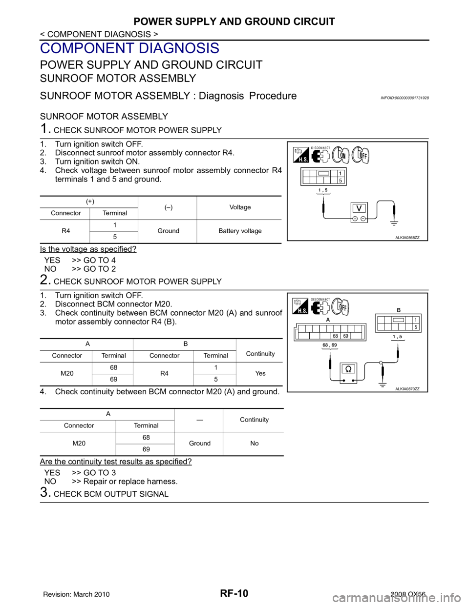
1. CHECK SUNROOF MOTOR POWER SUPPLY
1. Turn ignition switch OFF.
2. Disconnect sunroof motor assembly connector R4.
3. Turn ignition switch ON.
4. Check voltage between sunroof motor assembly connector R4 terminals 1 and 5 and ground.
Is the voltage as specified?
YES >> GO TO 4
NO >> GO TO 2
2. CHECK SUNROOF MOTOR POWER SUPPLY
1. Turn ignition switch OFF.
2. Disconnect BCM connector M20.
3. Check continuity between BCM connector M20 (A) and sunroof motor assembly connector R4 (B).
4. Check continuity between BCM connector M20 (A) and ground.
Are the continuity test results as specified?
YES >> GO TO 3
NO >> Repair or replace harness.
3. CHECK BCM OUTPUT SIGNAL
(+) (–)Voltage
Connector Terminal
R4 1
Ground Battery voltage
5
ALKIA0868ZZ
AB
Continuity
Connector Terminal Connector Terminal
M20 68
R4 1
Ye s
69 5
A —Contin u it y
Connector Terminal
M20 68
Ground No
69
ALKIA0870ZZ
Revision: March 2010 2008 QX56
Page 2995 of 4083

POWER SUPPLY AND GROUND CIRCUITRF-11
< COMPONENT DIAGNOSIS >
C
DE
F
G H
I
J
L
M A
B
RF
N
O P
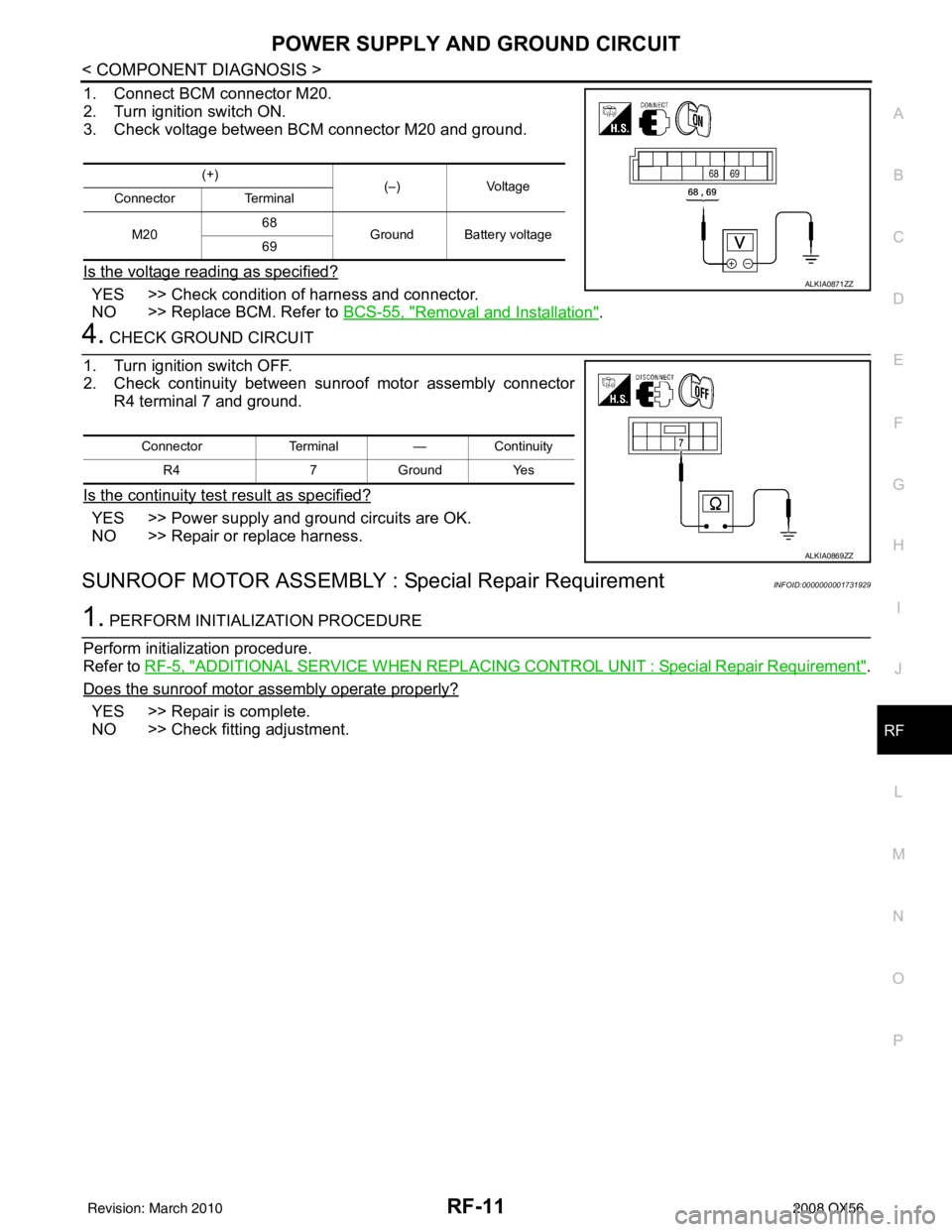
1. Connect BCM connector M20.
2. Turn ignition switch ON.
3. Check voltage between BCM connector M20 and ground.
Is the voltage reading as specified?
YES >> Check condition of harness and connector.
NO >> Replace BCM. Refer to BCS-55, "
Removal and Installation".
4. CHECK GROUND CIRCUIT
1. Turn ignition switch OFF.
2. Check continuity between sunroof motor assembly connector R4 terminal 7 and ground.
Is the continuity test result as specified?
YES >> Power supply and ground circuits are OK.
NO >> Repair or replace harness.
SUNROOF MOTOR ASSEMBLY : Special Repair RequirementINFOID:0000000001731929
1. PERFORM INITIALIZATION PROCEDURE
Perform initialization procedure.
Refer to RF-5, "
ADDITIONAL SERVICE WHEN REPLACING CO NTROL UNIT : Special Repair Requirement".
Does the sunroof motor assembly operate properly?
YES >> Repair is complete.
NO >> Check fitting adjustment.
(+) (–) Voltage
Connector Terminal
M20 68
Ground Battery voltage
69
ALKIA0871ZZ
Connector Terminal—Continuity
R4 7Ground Yes
ALKIA0869ZZ
Revision: March 2010 2008 QX56