2008 INFINITI QX56 air condition
[x] Cancel search: air conditionPage 3695 of 4083
TM-148
< SYMPTOM DIAGNOSIS >
SYSTEM SYMPTOM
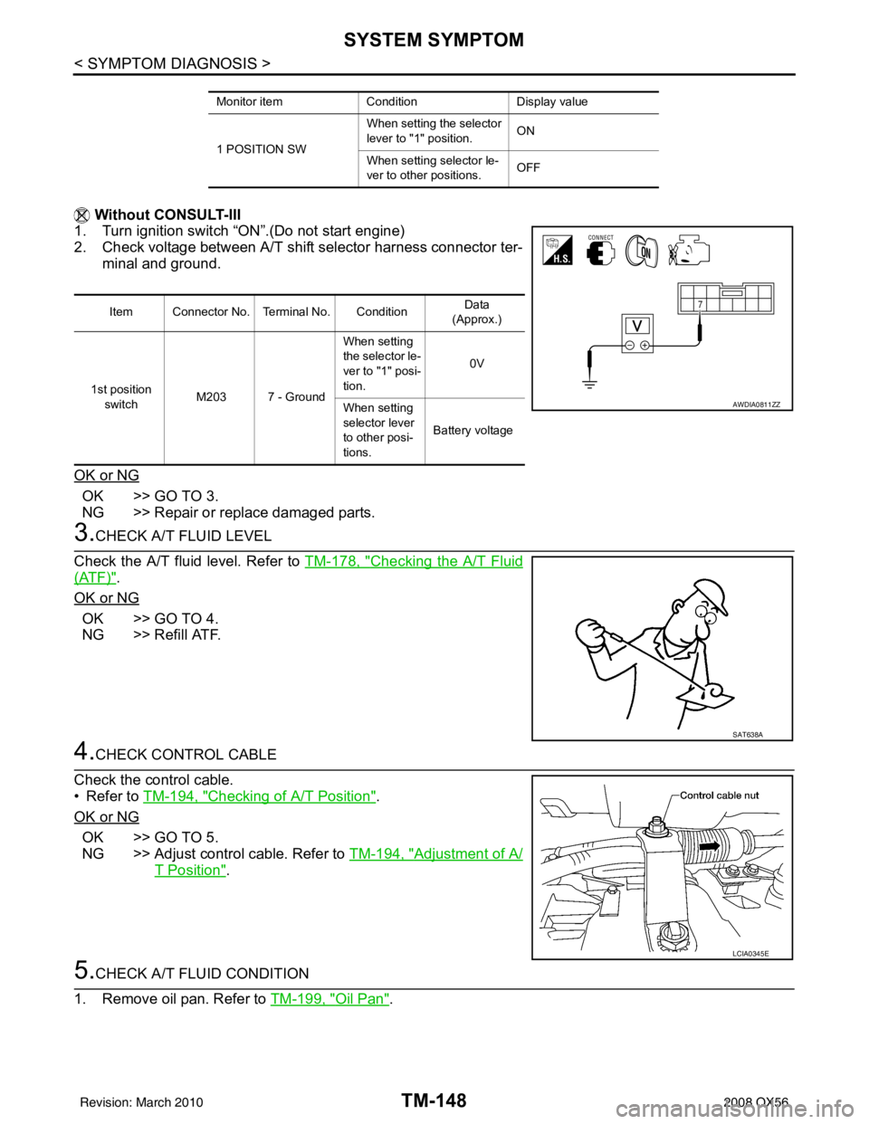
Without CONSULT-III
1. Turn ignition switch “ON”.(Do not start engine)
2. Check voltage between A/T shift selector harness connector ter-
minal and ground.
OK or NG
OK >> GO TO 3.
NG >> Repair or replace damaged parts.
3.CHECK A/T FLUID LEVEL
Check the A/T fluid level. Refer to TM-178, "
Checking the A/T Fluid
(ATF)".
OK or NG
OK >> GO TO 4.
NG >> Refill ATF.
4.CHECK CONTROL CABLE
Check the control cable.
• Refer to TM-194, "
Checking of A/T Position".
OK or NG
OK >> GO TO 5.
NG >> Adjust control cable. Refer to TM-194, "
Adjustment of A/
T Position".
5.CHECK A/T FLUID CONDITION
1. Remove oil pan. Refer to TM-199, "
Oil Pan".
Monitor itemConditionDisplay value
1 POSITION SW When setting the selector
lever to "1" position.
ON
When setting selector le-
ver to other positions. OFF
Item Connector No. Terminal No. Condition Data
(Approx.)
1st position switch M203 7 - Ground When setting
the selector le-
ver to "1" posi-
tion.
0V
When setting
selector lever
to other posi-
tions. Battery voltage
AWDIA0811ZZ
SAT638A
LCIA0345E
Revision: March 2010
2008 QX56
Page 3696 of 4083
SYSTEM SYMPTOMTM-149
< SYMPTOM DIAGNOSIS >
CEF
G H
I
J
K L
M A
B
TM
N
O P
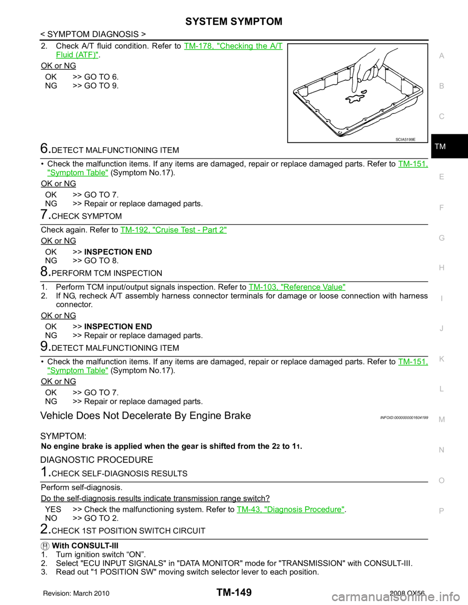
2. Check A/T fluid condition. Refer to TM-178, "Checking the A/T
Fluid (ATF)".
OK or NG
OK >> GO TO 6.
NG >> GO TO 9.
6.DETECT MALFUNCTIONING ITEM
• Check the malfunction items. If any items are damaged, repair or replace damaged parts. Refer to TM-151,
"Symptom Table" (Symptom No.17).
OK or NG
OK >> GO TO 7.
NG >> Repair or replace damaged parts.
7.CHECK SYMPTOM
Check again. Refer to TM-192, "
Cruise Test - Part 2"
OK or NG
OK >>INSPECTION END
NG >> GO TO 8.
8.PERFORM TCM INSPECTION
1. Perform TCM input/output signals inspection. Refer to TM-103, "
Reference Value"
2. If NG, recheck A/T assembly harness connector terminals for damage or loose connection with harness
connector.
OK or NG
OK >> INSPECTION END
NG >> Repair or replace damaged parts.
9.DETECT MALFUNCTIONING ITEM
• Check the malfunction items. If any items are damaged, repair or replace damaged parts. Refer to TM-151,
"Symptom Table" (Symptom No.17).
OK or NG
OK >> GO TO 7.
NG >> Repair or replace damaged parts.
Vehicle Does Not Decelerate By Engine BrakeINFOID:0000000001604199
SYMPTOM:
No engine brake is applied when the gear is shifted from the 22 to 11.
DIAGNOSTIC PROCEDURE
1.CHECK SELF-DIAGNOSIS RESULTS
Perform self-diagnosis.
Do the self-diagnosis results i ndicate transmission range switch?
YES >> Check the malfunctioning system. Refer to TM-43, "Diagnosis Procedure".
NO >> GO TO 2.
2.CHECK 1ST POSITION SWITCH CIRCUIT
With CONSULT-III
1. Turn ignition switch “ON”.
2. Select "ECU INPUT SIGNALS" in "DATA MONITO R" mode for "TRANSMISSION" with CONSULT-III.
3. Read out "1 POSITION SW" moving switch selector lever to each position.
SCIA5199E
Revision: March 2010 2008 QX56
Page 3697 of 4083
TM-150
< SYMPTOM DIAGNOSIS >
SYSTEM SYMPTOM
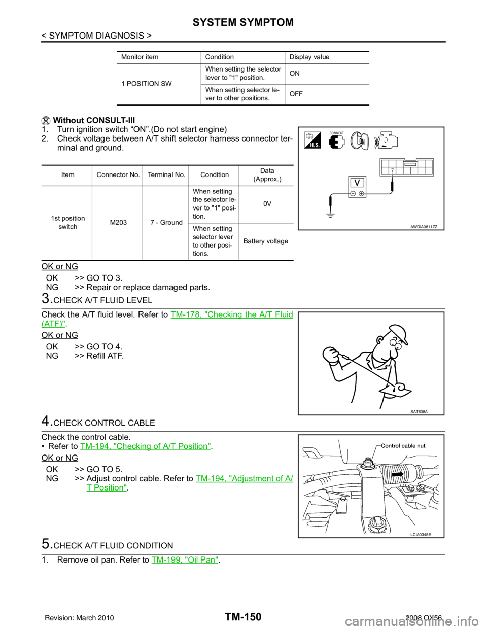
Without CONSULT-III
1. Turn ignition switch “ON”.(Do not start engine)
2. Check voltage between A/T shift selector harness connector ter-
minal and ground.
OK or NG
OK >> GO TO 3.
NG >> Repair or replace damaged parts.
3.CHECK A/T FLUID LEVEL
Check the A/T fluid level. Refer to TM-178, "
Checking the A/T Fluid
(ATF)".
OK or NG
OK >> GO TO 4.
NG >> Refill ATF.
4.CHECK CONTROL CABLE
Check the control cable.
• Refer to TM-194, "
Checking of A/T Position".
OK or NG
OK >> GO TO 5.
NG >> Adjust control cable. Refer to TM-194, "
Adjustment of A/
T Position".
5.CHECK A/T FLUID CONDITION
1. Remove oil pan. Refer to TM-199, "
Oil Pan".
Monitor itemConditionDisplay value
1 POSITION SW When setting the selector
lever to "1" position.
ON
When setting selector le-
ver to other positions. OFF
Item Connector No. Terminal No. Condition Data
(Approx.)
1st position switch M203 7 - Ground When setting
the selector le-
ver to "1" posi-
tion.
0V
When setting
selector lever
to other posi-
tions. Battery voltage
AWDIA0811ZZ
SAT638A
LCIA0345E
Revision: March 2010
2008 QX56
Page 3698 of 4083
SYSTEM SYMPTOMTM-151
< SYMPTOM DIAGNOSIS >
CEF
G H
I
J
K L
M A
B
TM
N
O P
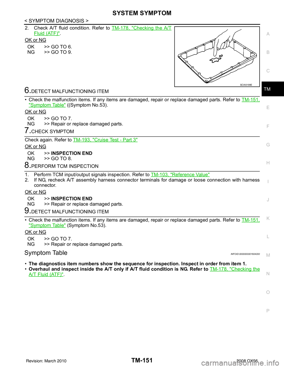
2. Check A/T fluid condition. Refer to TM-178, "Checking the A/T
Fluid (ATF)".
OK or NG
OK >> GO TO 6.
NG >> GO TO 9.
6.DETECT MALFUNCTIONING ITEM
• Check the malfunction items. If any items are damaged, repair or replace damaged parts. Refer to TM-151,
"Symptom Table" ((Symptom No.53).
OK or NG
OK >> GO TO 7.
NG >> Repair or replace damaged parts.
7.CHECK SYMPTOM
Check again. Refer to TM-193, "
Cruise Test - Part 3"
OK or NG
OK >>INSPECTION END
NG >> GO TO 8.
8.PERFORM TCM INSPECTION
1. Perform TCM input/output signals inspection. Refer to TM-103, "
Reference Value"
2. If NG, recheck A/T assembly harness connector terminals for damage or loose connection with harness
connector.
OK or NG
OK >> INSPECTION END
NG >> Repair or replace damaged parts.
9.DETECT MALFUNCTIONING ITEM
• Check the malfunction items. If any items are damaged, repair or replace damaged parts. Refer to TM-151,
"Symptom Table" (Symptom No.53).
OK or NG
OK >> GO TO 7.
NG >> Repair or replace damaged parts.
Symptom TableINFOID:0000000001604200
• The diagnostics item numbers s how the sequence for inspection. Inspect in order from item 1.
• Overhaul and inspect inside the A/T only if A/T fluid condition is NG. Refer to TM-178, "
Checking the
A/T Fluid (ATF)".
SCIA5199E
Revision: March 2010 2008 QX56
Page 3726 of 4083
A/T FLUIDTM-179
< ON-VEHICLE MAINTENANCE >
CEF
G H
I
J
K L
M A
B
TM
N
O P
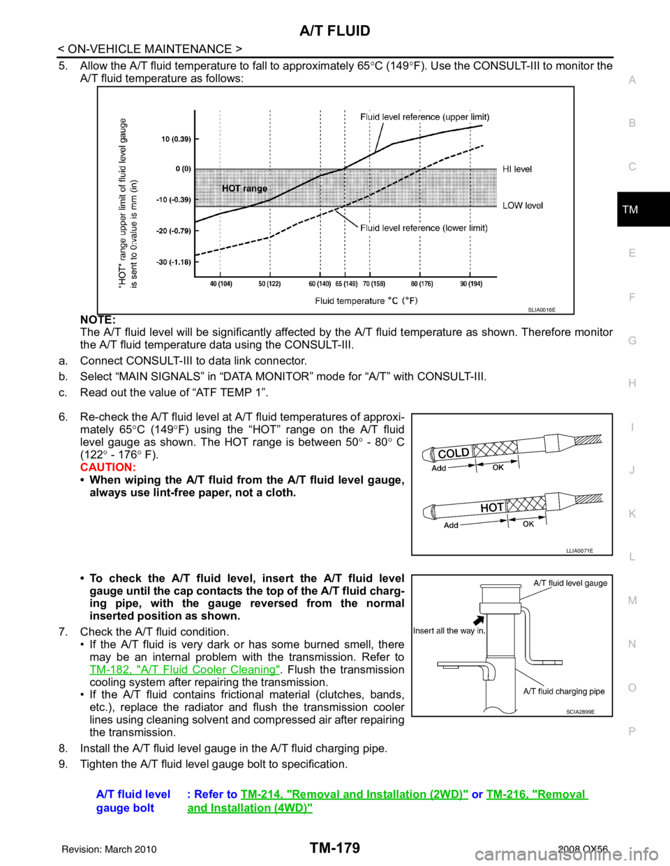
5. Allow the A/T fluid temperature to fall to approximately 65 °C (149° F). Use the CONSULT-III to monitor the
A/T fluid temperature as follows:
NOTE:
The A/T fluid level will be significantly affected by the A/T fluid temperature as shown. Therefore monitor
the A/T fluid temperature data using the CONSULT-III.
a. Connect CONSULT-III to data link connector.
b. Select “MAIN SIGNALS” in “DATA MO NITOR” mode for “A/T” with CONSULT-III.
c. Read out the value of “ATF TEMP 1”.
6. Re-check the A/T fluid level at A/T fluid temperatures of approxi-
mately 65° C (149°F) using the “HOT” range on the A/T fluid
level gauge as shown. The HOT range is between 50 ° - 80° C
(122° - 176 ° F).
CAUTION:
• When wiping the A/T fluid from the A/T fluid level gauge, always use lint-free paper, not a cloth.
• To check the A/T fluid level, insert the A/T fluid level gauge until the cap contacts the top of the A/T fluid charg-
ing pipe, with the gauge reversed from the normal
inserted position as shown.
7. Check the A/T fluid condition. • If the A/T fluid is very dark or has some burned smell, there
may be an internal problem with the transmission. Refer to
TM-182, "
A/T Fluid Cooler Cleaning". Flush the transmission
cooling system after repairing the transmission.
• If the A/T fluid contains frictional material (clutches, bands, etc.), replace the radiator and flush the transmission cooler
lines using cleaning solvent and compressed air after repairing
the transmission.
8. Install the A/T fluid level gauge in the A/T fluid charging pipe.
9. Tighten the A/T fluid level gauge bolt to specification.
SLIA0016E
LLIA0071E
A/T fluid level
gauge bolt : Refer to
TM-214, "Removal and Installation (2WD)" or TM-216, "Removal
and Installation (4WD)"
SCIA2899E
Revision: March 2010 2008 QX56
Page 3841 of 4083

VTL-1
VENTILATION, HEATER & AIR CONDITIONER
C
DE
F
G H
J
K L
M
SECTION VTL
A
B
VTL
N
O P
CONTENTS
VENTILATION SYSTEM
PRECAUTION ....... ........................................2
PRECAUTIONS .............................................. .....2
Precaution for Supplemental Restraint System
(SRS) "AIR BAG" and "SEAT BELT PRE-TEN-
SIONER" ............................................................. ......
2
Precaution Necessary for Steering Wheel Rota-
tion After Battery Disconnect ............................... ......
2
Precaution for Working with HFC-134a (R-134a) ......3
Precaution for Procedure without Cowl Top Cover ......3
PREPARATION ............................................4
PREPARATION .............................................. .....4
Commercial Service Tool .................................... ......4
FUNCTION DIAGNOSIS ...............................5
IN-CABIN MICROFILTER .............................. .....5
Description .......................................................... ......5
ON-VEHICLE MAINTENANCE .....................6
IN-CABIN MICROFILTER .............................. .....6
Removal and Installation ...........................................6
ON-VEHICLE REPAIR .... ..............................7
CONTROL UNIT ..................................................7
Removal and Installation ...........................................7
IN-VEHICLE SENSOR ................................... .....9
Removal and Installation ...........................................9
OPTICAL SENSOR ........................................ ....10
Removal and Installation .........................................10
INTAKE SENSOR ..............................................11
Removal and Installation .........................................11
BLOWER MOTOR .......................................... ....12
Component .......................................................... ....12
Removal and Installation ..................................... ....12
IN-CABIN MICROFILTER .................................14
Removal and Installation .........................................14
HEATER & COOLING UNIT ASSEMBLY ........15
Component ..............................................................15
Removal and Installation .........................................16
HEATER CORE .................................................18
Component ..............................................................18
Removal and Installation .........................................19
DEFROSTER DOOR MOTOR ..........................21
Removal and Installation .........................................21
INTAKE DOOR MOTOR ...................................22
Removal and Installation .........................................22
MODE DOOR MOTOR ......................................23
Components ............................................................23
Removal and Installation .........................................24
AIR MIX DOOR MOTOR ...................................25
Component ..............................................................25
Removal and Installation .........................................26
VARIABLE BLOWER CONTROL .....................28
Components ............................................................28
Removal and Installation .........................................29
DUCTS AND GRILLES .....................................30
Component ..............................................................30
Removal and Installation .........................................33
REFRIGERANT LINES .....................................35
Removal and Installation for Front Evaporator ........35
Removal and Installation for Rear Evaporator .........36
Removal and Installation for Rear Expansion
Valve ........................................................................
37
Revision: March 2010 2008 QX56
Page 3845 of 4083
IN-CABIN MICROFILTERVTL-5
< FUNCTION DIAGNOSIS >
C
DE
F
G H
J
K L
M A
B
VTL
N
O P
FUNCTION DIAGNOSIS
IN-CABIN MICROFILTER
DescriptionINFOID:0000000001516601
FUNCTION
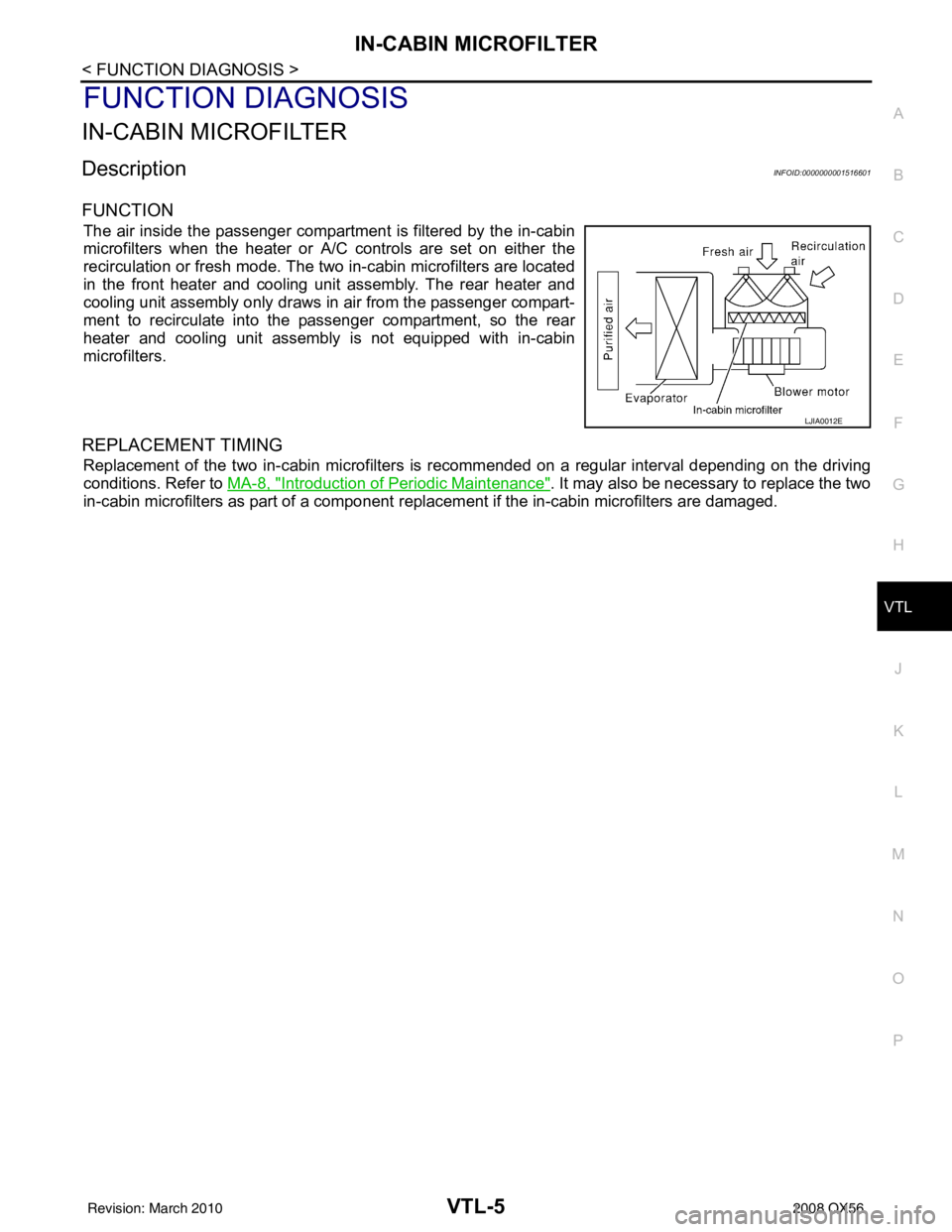
The air inside the passenger compartment is filtered by the in-cabin
microfilters when the heater or A/C controls are set on either the
recirculation or fresh mode. The two in-cabin microfilters are located
in the front heater and cooling unit assembly. The rear heater and
cooling unit assembly only draws in air from the passenger compart-
ment to recirculate into the passenger compartment, so the rear
heater and cooling unit assembly is not equipped with in-cabin
microfilters.
REPLACEMENT TIMING
Replacement of the two in-cabin microfilters is recommended on a regular interval depending on the driving
conditions. Refer to MA-8, "
Introduction of Periodic Maintenance". It may also be necessary to replace the two
in-cabin microfilters as part of a component r eplacement if the in-cabin microfilters are damaged.
LJIA0012E
Revision: March 2010 2008 QX56
Page 3880 of 4083
WCS
DIAGNOSIS AND REPAIR WORKFLOWWCS-3
< BASIC INSPECTION >
C
DE
F
G H
I
J
K L
M B A
O P
BASIC INSPECTION
DIAGNOSIS AND REPAIR WORKFLOW
Work FlowINFOID:0000000001697652
DETAILED FLOW
1.OBTAIN INFORMATION ABOUT SYMPTOM
Interview the customer to obtain as much informa tion as possible about the conditions and environment under
which the malfunction occurred.
>> GO TO 2
2.CHECK SYMPTOM
• Check the symptom based on the information obtained from the customer.
• Check to see if any other malfunctions are present.
>> GO TO 3
3.CHECK CONSULT-III SELF -DIAGNOSIS RESULTS
Connect CONSULT-III and perform “SELF-DIAGNOSIS”. Refer to MWI-25, "
CONSULT-III Function (METER/
M&A)".
Are self-diagnosis results normal?
YES >> GO TO 4
NO >> Repair or replace the malfunctioning parts, GO TO 5
4.NARROW DOWN MALFUNCTIONING PART S THROUGH SYMPTOM DIAGNOSIS
Perform symptom diagnosis and repair or r eplace the identified malfunctioning parts.
>> GO TO 5
5.FINAL CHECK
Check that the warning buzzer in the combination meter operates normally.
Does it operate normally?
YES >> Inspection End.
NO >> GO TO 1
Revision: March 2010 2008 QX56