Page 2931 of 4083
PWC-90
< ECU DIAGNOSIS >
FRONT POWER WINDOW SWITCH
AAKIA0236GB
Revision: March 20102008 QX56
Page 2932 of 4083
FRONT POWER WINDOW SWITCHPWC-91
< ECU DIAGNOSIS >
C
DE
F
G H
I
J
L
M A
B
PWC
N
O P
AAKIA0237GB
Revision: March 2010 2008 QX56
Page 2933 of 4083
PWC-92
< ECU DIAGNOSIS >
FRONT POWER WINDOW SWITCH
AAKIA0238GB
Revision: March 20102008 QX56
Page 2934 of 4083
FRONT POWER WINDOW SWITCHPWC-93
< ECU DIAGNOSIS >
C
DE
F
G H
I
J
L
M A
B
PWC
N
O P
Fail SafeINFOID:0000000001735742
FAIL-SAFE CONTROL
Switches to fail-safe control when malfunction is detected in encoder signal that detects up/down speed and
direction of door glass. Switches to fail-safe cont rol when error beyond regulation value is detected between
the fully closed position and the actual position of the glass.
AAKIA0239GB
Revision: March 2010 2008 QX56
Page 2935 of 4083

PWC-94
< ECU DIAGNOSIS >
FRONT POWER WINDOW SWITCH
It changes to condition before initialization and the following functions do not operate when switched to fail-
safe control.
• Auto-up operation
• Anti-pinch function
• Retained power function
Perform initial operation to recover when switched to fa il-safe mode. However, it switches back to fail-safe
control when malfunction is found in power window switch or in motor.
Error Error condition
Pulse sensor malfunction When only one side of pulse signal is being detected for more than the specified value.
Both pulse sensors mal-
function When both pulse signals have not been detected for more than the specified value during glass open/
close operation.
Pulse direction malfunction When the pulse signal that is detected during glass open/close operation detects the opposite condition
of power window motor operating direction.
Glass recognition position
malfunction 1 When it detects the error between glass fully closed position in power window switch memory and actual
fully closed position during glass open/close operation is more than the specified value.
Glass recognition position
malfunction 2 When it detects pulse count more than the value of glass full stroke during glass open/close operation.
Malfunction of not yet up-
dated closed position of
glass When glass open/close operation is continuously performed without fully closing more than the specified
value (approximately 10 strokes).
Revision: March 2010
2008 QX56
Page 2981 of 4083

REAR DRIVE SHAFTRAX-13
< DISASSEMBLY AND ASSEMBLY >
CEF
G H
I
J
K L
M A
B
RAX
N
O P
• Check the ball sliding surface for any co mpression scars, cracks, or fractures.
• Check for any damage to the serrated part. CAUTION:
If any defective conditions are found, install a new housing, ball cage, steel ball, and inner race as a
set.
ASSEMBLY
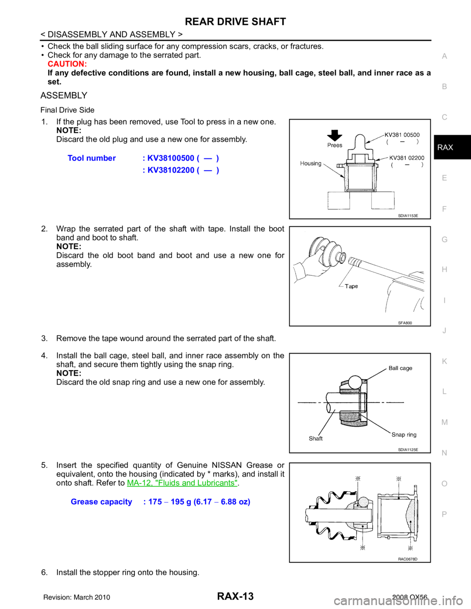
Final Drive Side
1. If the plug has been removed, use Tool to press in a new one. NOTE:
Discard the old plug and use a new one for assembly.
2. Wrap the serrated part of the shaft with tape. Install the boot band and boot to shaft.
NOTE:
Discard the old boot band and boot and use a new one for
assembly.
3. Remove the tape wound around the serrated part of the shaft.
4. Install the ball cage, steel ball, and inner race assembly on the shaft, and secure them tightly using the snap ring.
NOTE:
Discard the old snap ring and use a new one for assembly.
5. Insert the specified quantity of Genuine NISSAN Grease or equivalent, onto the housing (indicated by * marks), and install it
onto shaft. Refer to MA-12, "
Fluids and Lubricants".
6. Install the stopper ring onto the housing. Tool number : KV38100500 ( — )
: KV38102200 ( — )
SDIA1153E
SFA800
SDIA1125E
Grease capacity : 175 − 195 g (6.17 − 6.88 oz)
RAC0678D
Revision: March 2010 2008 QX56
Page 2982 of 4083

RAX-14
< DISASSEMBLY AND ASSEMBLY >
REAR DRIVE SHAFT
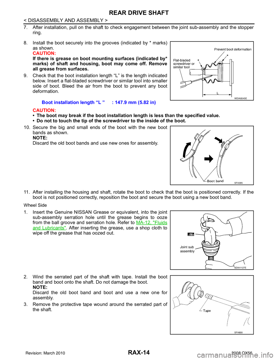
7. After installation, pull on the shaft to check engagement between the joint sub-assembly and the stopper
ring.
8. Install the boot securely into the grooves (indicated by * marks) as shown.
CAUTION:
If there is grease on boot mo unting surfaces (indicated by*
marks) of shaft and housing, boot may come off. Remove
all grease from surfaces.
9. Check that the boot installation length “L” is the length indicated below. Insert a flat-bladed screwdriver or similar tool into smaller
side of boot. Bleed the air from the boot to prevent any boot
deformation.
CAUTION:
• The boot may break if the boot installation length is less than the specified value.
• Do not to touch the tip of the screw driver to the inside of the boot.
10. Secure the big and small ends of the boot with the new boot bands as shown.
NOTE:
Discard the old boot bands and use new ones for assembly.
11. After installing the housing and shaft, rotate the boot to check that the boot is positioned correctly. If the boot is not positioned correctly, reposition t he boot and secure the boot using a new boot band.
Wheel Side
1. Insert the Genuine NISSAN Grease or equivalent, into the joint
sub-assembly serration hole until the grease begins to ooze
from the ball groove and serration hole. Refer to MA-12, "
Fluids
and Lubricants". After inserting the grease, use a shop cloth to
wipe off the grease that has oozed out.
2. Wind the serrated part of the shaft with tape. Install the boot
band and boot onto the shaft. Do not damage the boot.
NOTE:
Discard the old boot band and boot and use a new one for
assembly.
3. Remove the protective tape wound around the serrated part of the shaft. Boot installation length
“L ” : 147.9 mm (5.82 in)
WDIA0045E
SFA395
SDIA1127E
SFA800
Revision: March 2010 2008 QX56
Page 2983 of 4083

REAR DRIVE SHAFTRAX-15
< DISASSEMBLY AND ASSEMBLY >
CEF
G H
I
J
K L
M A
B
RAX
N
O P
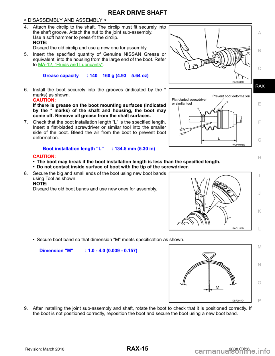
4. Attach the circlip to the shaft. The circlip must fit securely into
the shaft groove. Attach the nut to the joint sub-assembly.
Use a soft hammer to press-fit the circlip.
NOTE:
Discard the old circlip and use a new one for assembly.
5. Insert the specified quantity of Genuine NISSAN Grease or equivalent, into the housing from the large end of the boot. Refer
to MA-12, "
Fluids and Lubricants".
6. Install the boot securely into the grooves (indicated by the * marks) as shown.
CAUTION:
If there is grease on the bo ot mounting surfaces (indicated
by the * marks) of the shaft and housing, the boot may
come off. Remove all grease from the shaft surfaces.
7. Check that the boot installation length “L” is the specified length. Insert a flat-bladed screwdriver or similar tool into the smaller
side of the boot. Bleed the air from the boot to prevent boot
deformation.
CAUTION:
• The boot may break if the boot installation length is less than the specified length.
• Do not contact inside surface of boot with the tip of the screwdriver.
8. Secure the big and small ends of the boot using new boot bands using Tool as shown.
NOTE:
Discard the old boot bands and use new ones for assembly.
• Secure boot band so that dimension "M" meets specification as shown.
9. After installing the joint sub-assembly and shaft, rota te the boot to check that it is positioned correctly. If
the boot is not positioned correctly, reposition the boot and secure the boot using a new boot band.
Grease capacity : 140
− 160 g (4.93 − 5.64 oz)
RAC0049D
Boot installation length “L” : 134.5 mm (5.30 in)
WDIA0046E
RAC1133D
Dimension "M" : 1.0 - 4.0 (0.039 - 0.157)
DSF0047D
Revision: March 2010 2008 QX56