2008 INFINITI QX56 oil pressure
[x] Cancel search: oil pressurePage 2206 of 4083

HA-1
VENTILATION, HEATER & AIR CONDITIONER
C
DE
F
G H
J
K L
M
SECTION HA
A
B
HA
N
O P
CONTENTS
HEATER & AIR CONDITIONING SYSTEM
PRECAUTION ....... ........................................3
PRECAUTIONS .............................................. .....3
Precaution for Supplemental Restraint System
(SRS) "AIR BAG" and "SEAT BELT PRE-TEN-
SIONER" ............................................................. ......
3
Precaution Necessary for Steering Wheel Rota-
tion After Battery Disconnect ............................... ......
3
Precaution for Working with HFC-134a (R-134a) ......4
Precaution for Procedure without Cowl Top Cover ......4
Contaminated Refrigerant .........................................4
General Refrigerant Precaution ................................5
Precaution for Leak Detection Dye ...........................5
A/C Identification Label .............................................5
Precaution for Refrigerant Connection ......................5
Precaution for Service of Compressor ................ ....10
Precaution for Service Equipment ....................... ....10
PREPARATION ...........................................13
PREPARATION .............................................. ....13
Special Service Tool ........................................... ....13
HFC-134a (R-134a) Service Tool and Equipment ....13
Commercial Service Tool ........................................16
FUNCTION DIAGNOSIS ..............................17
REFRIGERATION SYSTEM .......................... ....17
Refrigerant Cycle ................................................ ....17
Refrigerant System Protection ................................17
OIL .................................................................. ....19
Maintenance of Oil in Compressor ...................... ....19
ON-VEHICLE MAINTENANCE ....................20
REFRIGERATION SYSTEM .......................... ....20
HFC-134a (R-134a) Service Procedure ..................20
OIL .................................................................. ....22
Maintenance of Oil Quantity in Compressor ....... ....22
FLUORESCENT LEAK DETECTOR ................24
Checking of Refrigerant Leaks ................................24
Checking System for Leaks Using the Fluorescent
Dye Leak Detector ............................................... ....
24
Dye Injection ............................................................24
ELECTRICAL LEAK DETECTOR ....................26
Checking of Refrigerant Leaks ................................26
Electronic Refrigerant Leak Detector ................... ....26
ON-VEHICLE REPAIR .................................29
REFRIGERATION SYSTEM .............................29
Component .......................................................... ....29
COMPRESSOR .................................................31
Removal and Installation for Compressor ...............31
Removal and Installation for Compressor Clutch ....32
LOW-PRESSURE FLEXIBLE HOSE ................36
Removal and Installation for Low-Pressure Flexi-
ble Hose .............................................................. ....
36
LOW-PRESSURE PIPE ....................................37
Removal and Installation for Low-Pressure Pipe .....37
Removal and Installation for Rear High- and Low-
Pressure A/C and Heater Core Pipes ......................
37
Removal and Installation for Underfloor Rear
High- and Low-Pressure A/C and Heater Core
Pipes ........................................................................
38
HIGH-PRESSURE FLEXIBLE HOSE ...............40
Removal and Installation for High-Pressure Flexi-
ble Hose ..................................................................
40
HIGH-PRESSURE PIPE ....................................41
Removal and Installation for High-Pressure Pipe ....41
Removal and Installation for Rear High- and Low-
Pressure A/C and Heater Core Pipes .................. ....
41
Removal and Installation for Underfloor Rear
High- and Low-Pressure A/C and Heater Core
Pipes ........................................................................
43
Revision: March 2010 2008 QX56
Page 2214 of 4083

PRECAUTIONSHA-9
< PRECAUTION >
C
DE
F
G H
J
K L
M A
B
HA
N
O P
*: Always check with the Parts Department for the latest parts information.
WARNING:
Make sure all refrigerant is discharged into the recycling equipment and the pressure in the system is
less than atmospheric pressure. Then gradually loo sen the discharge side hose fitting and remove it.
CAUTION:
When replacing or cleaning refrigerant cycle components, observe the following.
• When the compressor is removed, store it in the same position as it is when mounted on the car.
Failure to do so will cause oil to enter the low pressure chamber.
• When connecting tubes, always use a to rque wrench and a back-up wrench.
• After disconnecting tubes, immediately plug all op enings to prevent entry of dirt and moisture.
• When installing an air conditione r in the vehicle, connect the pipes as the final stage of the opera-
tion. Do not remove the seal caps of pipes and other components until just before required for con-
nection.
• Allow components stored in cool areas to warm to working area temperature before removing seal
caps. This prevents condensation from forming inside A/C components.
• Thoroughly remove moisture from the refrigeration system before charging the refrigerant.
• Always replace used O-rings.
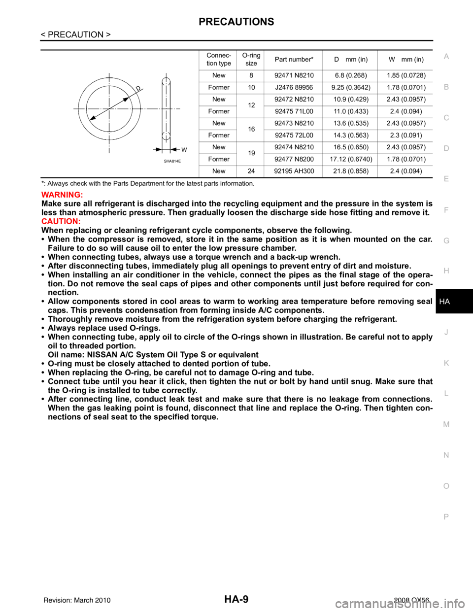
• When connecting tube, apply oil to circle of the O-ri ngs shown in illustration. Be careful not to apply
oil to threaded portion.
Oil name: NISSAN A/C System Oil Type S or equivalent
• O-ring must be closely attached to dented portion of tube.
• When replacing the O-ring, be careful not to damage O-ring and tube.
• Connect tube until you hear it cl ick, then tighten the nut or bolt by hand until snug. Make sure that
the O-ring is installed to tube correctly.
• After connecting line, conduct leak test and make sure that there is no leakage from connections.
When the gas leaking point is f ound, disconnect that line and replace the O-ri ng. Then tighten con-
nections of seal seat to the specified torque.
Connec-
tion type O-ring
size Part number* D mm (in) W mm (in)
New 8 92471 N8210 6.8 (0.268) 1.85 (0.0728)
Former 10 J2476 89956 9.25 (0.3642) 1.78 (0.0701) New 1292472 N8210 10.9 (0.429) 2.43 (0.0957)
Former 92475 71L00 11.0 (0.433) 2.4 (0.094)
New 1692473 N8210 13.6 (0.535) 2.43 (0.0957)
Former 92475 72L00 14.3 (0.563) 2.3 (0.091)
New 1992474 N8210 16.5 (0.650) 2.43 (0.0957)
Former 92477 N8200 17.12 (0.6740) 1.78 (0.0701)
New 24 92195 AH300 21.8 (0.858) 2.4 (0.094)
SHA814E
Revision: March 2010 2008 QX56
Page 2216 of 4083

PRECAUTIONSHA-11
< PRECAUTION >
C
DE
F
G H
J
K L
M A
B
HA
N
O P
The oil contained inside the vacuum pump is not compatible with the
specified oil for HFC-134a (R-134a) A/C systems. The vent side of
the vacuum pump is exposed to atmospheric pressure so the vac-
uum pump oil may migrate out of the pump into the service hose.
This is possible when the pump is switched off after evacuation (vac-
uuming) and hose is connected to it.
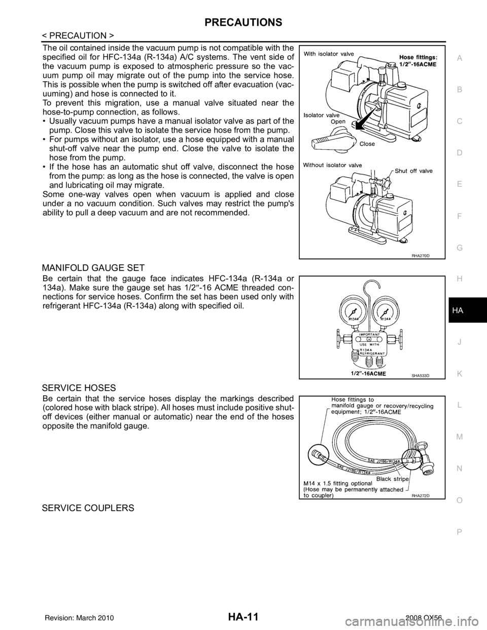
To prevent this migration, use a manual valve situated near the
hose-to-pump connection, as follows.
• Usually vacuum pumps have a manual isolator valve as part of the
pump. Close this valve to isolate the service hose from the pump.
• For pumps without an isolator, use a hose equipped with a manual shut-off valve near the pump end. Close the valve to isolate the
hose from the pump.
• If the hose has an automatic shut off valve, disconnect the hose from the pump: as long as the hose is connected, the valve is open
and lubricating oil may migrate.
Some one-way valves open when vacuum is applied and close
under a no vacuum condition. Such valves may restrict the pump's
ability to pull a deep vacuum and are not recommended.
MANIFOLD GAUGE SET
Be certain that the gauge face indicates HFC-134a (R-134a or
134a). Make sure the gauge set has 1/2 ″-16 ACME threaded con-
nections for service hoses. Confirm the set has been used only with
refrigerant HFC-134a (R-134a) along with specified oil.
SERVICE HOSES
Be certain that the service hoses display the markings described
(colored hose with black stripe). All hoses must include positive shut-
off devices (either manual or aut omatic) near the end of the hoses
opposite the manifold gauge.
SERVICE COUPLERS
RHA270D
SHA533D
RHA272D
Revision: March 2010 2008 QX56
Page 2222 of 4083

REFRIGERATION SYSTEMHA-17
< FUNCTION DIAGNOSIS >
C
DE
F
G H
J
K L
M A
B
HA
N
O P
FUNCTION DIAGNOSIS
REFRIGERATION SYSTEM
Refrigerant CycleINFOID:0000000001516641
REFRIGERANT FLOW
The refrigerant flows in the standard pattern, that is, through the compressor, the condenser with liquid tank,
through the front and rear evaporators, and back to the compressor. The refrigerant evaporation through the
evaporator coils are controlled by front and rear externally equalized expansion valves, located inside the front
and rear evaporator cases.
Refrigerant System ProtectionINFOID:0000000001516642
REFRIGERANT PRESSURE SENSOR
The refrigerant system is protected against excessively hi gh or low pressures by the refrigerant pressure sen-
sor, located on the condenser. If the system pressure rises above or falls below the specifications, the refriger-
ant pressure sensor detects the pressure inside the refrigerant line and sends a voltage signal to the ECM.
The ECM de-energizes the A/C relay to disengage the magnetic compressor clutch when pressure on the high
pressure side detected by refrigerant pressu re sensor is over about 2,746 kPa (28 kg/cm
2, 398 psi), or below
about 120 kPa (1.22 kg/cm
2, 17.4 psi).
PRESSURE RELIEF VALVE
The refrigerant system is also protected by a pressure relief valve, located in the rear head of the compressor.
When the pressure of refrigerant in the system incr eases to an abnormal level [more than 2,990 kPa (30.5 kg/
Revision: March 2010 2008 QX56
Page 2228 of 4083

OIL
HA-23
< ON-VEHICLE MAINTENANCE >
C
D E
F
G H
J
K L
M A
B
HA
N
O P
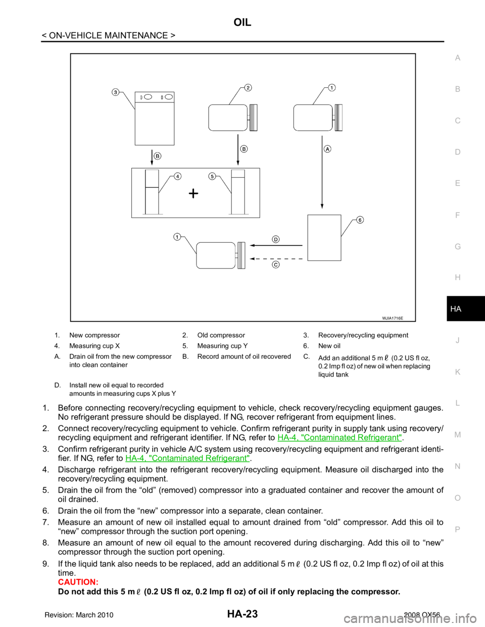
1. Before connecting recovery/recycling equipment to vehicle, check recovery/recycling equipment gauges.
No refrigerant pressure should be displayed. If NG, recover refrigerant from equipment lines.
2. Connect recovery/recycling equipment to vehicle. Confir m refrigerant purity in supply tank using recovery/
recycling equipment and refrigerant identifier. If NG, refer to HA-4, "
Contaminated Refrigerant".
3. Confirm refrigerant purity in vehicle A/C system using recovery/recycling equipment and refrigerant identi-
fier. If NG, refer to HA-4, "
Contaminated Refrigerant".
4. Discharge refrigerant into the refrigerant recove ry/recycling equipment. Measure oil discharged into the
recovery/recycling equipment.
5. Drain the oil from the “old” (removed) compress or into a graduated container and recover the amount of
oil drained.
6. Drain the oil from the “new” compressor into a separate, clean container.
7. Measure an amount of new oil installed equal to am ount drained from “old” compressor. Add this oil to
“new” compressor through the suction port opening.
8. Measure an amount of new oil equal to the amount recovered during discharging. Add this oil to “new” compressor through the suction port opening.
9. If the liquid tank also needs to be replaced, add an additional 5 m (0.2 US fl oz, 0.2 Imp fl oz) of oil at this time.
CAUTION:
Do not add this 5 m (0.2 US fl oz, 0.2 Imp fl oz) of oil if only replacing the compressor.
1. New compressor2. Old compressor3. Recovery/recycling equipment
4. Measuring cup X 5. Measuring cup Y6. New oil
A. Drain oil from the new compressor into clean container B. Record amount of oil recovered C.
Add an additional 5 m (0.2 US fl oz,
0.2 Imp fl oz) of new oil when replacing
liquid tank
D. Install new oil equal to recorded amounts in measuring cups X plus Y
WJIA1716E
Revision: March 2010 2008 QX56
Page 2229 of 4083

HA-24
< ON-VEHICLE MAINTENANCE >
FLUORESCENT LEAK DETECTOR
FLUORESCENT LEAK DETECTOR
Checking of Refrigerant LeaksINFOID:0000000001516646
PRELIMINARY CHECK
Perform a visual inspection of all refrigeration parts, fittings, hoses and components for signs of A/C oil leak-
age, damage, and corrosion. Any A/C oil leakage may indicate an area of refrigerant leakage. Allow extra
inspection time in these areas when using either an el ectronic refrigerant leak detector (J-41995) or fluores-
cent dye leak detector (J-42220).
If any dye is observed using a fluorescent dye leak detector (J-42220), confirm the leak using a electronic
refrigerant leak detector (J-41995). It is possible that the dye is from a prior leak that was repaired and not
properly cleaned.
When searching for leaks, do not stop when one leak is found but continue to check for additional leaks at all
system components and connections.
When searching for refrigerant leaks using an electronic refrigerant leak detector (J-41995), move the probe
along the suspected leak area at 25 - 50 mm (1 - 2 in) per second and no further than 6 mm (1/4 in) from the
component.
CAUTION:
Moving the electronic refrigerant l eak detector probe slower and closer to the suspected leak area will
improve the chances of finding a leak.
Checking System for L eaks Using the Fluorescent Dye Leak DetectorINFOID:0000000001516647
1. Check the A/C system for leaks using the fluorescent dye leak detector and safety goggles (J-42220) in a
low sunlight area (area without windows preferable). Il luminate all components, fittings and lines. The dye
will appear as a bright green/yellow area at the point of leakage. Fluorescent dye observed at the evapo-
rator drain opening indicates an evaporator core asse mbly leak (tubes, core or expansion valve).
2. If the suspected area is difficult to see, use an adjustable mirror or wipe the area with a clean shop rag or cloth, then inspect the shop rag or cloth with the fl uorescent dye leak detector (J-42220) for dye residue.
3. After the leak is repaired, remove any residual dye using refrigerant dye cleaner (J-43872) to prevent
future misdiagnosis.
4. Perform a system performance check and then verify t he leak repair using a electronic refrigerant leak
detector (J-41995).
NOTE:
• Other gases in the work area or substances on the A/C components, for example, anti-freeze, wind-
shield washer fluid, solvents and oils, may falsely tri gger the leak detector. Make sure the surfaces to be
checked are clean.
• Clean with a dry cloth or blow off with shop air.
• Do not allow the sensor tip of the electronic refri gerant leak detector (J-41995) to contact with any sub-
stance. This can also cause false readings and may damage the detector.
Dye InjectionINFOID:0000000001516648
NOTE:
This procedure is only necessary when recharging the system or when the compressor has seized and must
be replaced.
1. Check the A/C system static (at rest) pressure . Pressure must be at least 345 kPa (3.52 kg/cm
2 , 50 psi).
2. Pour one bottle 7.4 cc (1/4 ounce) of the HFC-134a (R -134a) fluorescent leak detection dye (J-41447) into
the HFC-134a (R-134a) dye injector (J-41459).
CAUTION:
If repairing the A/C system or replacing a co mponent, pour the HFC-134a (R-134a) fluorescent leak
detection dye (J-41447) directly into the open system connection and proceed with the service
procedures.
3. Connect the refrigerant dye injector (J-41459) to the low-pressure service valve.
4. Start the engine and switch the A/C system ON.
5. When the A/C system is operating (compressor running), inject one bottle 7.4 cc (1/4 ounce) of HFC-134a (R-134a) fluorescent leak detection dye (J-41447) through the low-pressure service valve using HFC-
134a (R-134a) dye injector (J-41459). Refer to the manufacturer's operating instructions.
Revision: March 2010 2008 QX56
Page 2237 of 4083

HA-32
< ON-VEHICLE REPAIR >
COMPRESSOR
• Replace the O-rings of the low-pressure flexible hose and high-pressure flexible hose with new
ones, apply compressor oil to the O-rings when installing them.
• After recharging the A/C system with refrigerant, check for leaks.
Removal and Installation for Compressor ClutchINFOID:0000000001516653
Magnet Clutch Assembly
REMOVAL
1. Remove the compressor. Refer to HA-31, "Removal and Installation for Compressor" .
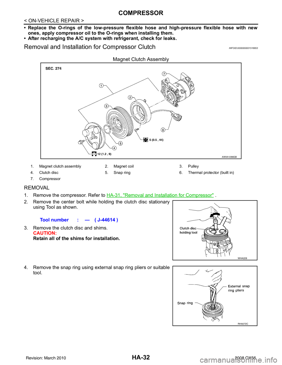
2. Remove the center bolt while holding the clutch disc stationary using Tool as shown.
3. Remove the clutch disc and shims. CAUTION:
Retain all of the shims for installation.
4. Remove the snap ring using external snap ring pliers or suitable tool.
AWIIA1286GB
1. Magnet clutch assembly 2. Magnet coil 3. Pulley
4. Clutch disc 5. Snap ring 6. Thermal protector (built in)
7. Compressor
Tool number : — ( J-44614 )
WHA228
RHA072C
Revision: March 2010 2008 QX56
Page 2241 of 4083

HA-36
< ON-VEHICLE REPAIR >
LOW-PRESSURE FLEXIBLE HOSE
LOW-PRESSURE FLEXIBLE HOSE
Removal and Installation for Low-Pressure Flexible HoseINFOID:0000000001516654
REMOVAL
1. Remove the engine air cleaner and air ducts. Refer to EM-25, "Removal and Installation".
2. Discharge the refrigerant. Refer to HA-20, "
HFC-134a (R-134a) Service Procedure".
CAUTION:
Cap or wrap the joint of the pipe with suitable mate rial such as vinyl tape to avoid the entry of air.
3. Remove the low-pressure flexible hose.
INSTALLATION
Installation is in the reverse order of removal.
Refer to HA-29, "
Component".
CAUTION:
• Replace the O-ring of the low-pressure flexible hose with a new one, then apply compressor oil to it
when installing it.
• After charging refrigerant, check for leaks.
Revision: March 2010 2008 QX56