2008 INFINITI QX56 oil pressure
[x] Cancel search: oil pressurePage 2602 of 4083
MA-4
< PREPARATION >
PREPARATION
PREPARATION
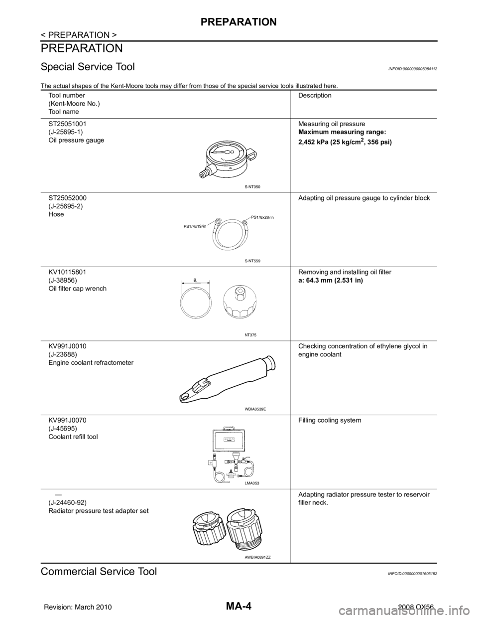
Special Service ToolINFOID:0000000006054112
The actual shapes of the Kent-Moore tools may differ from those of the special service tools illustrated here.
Commercial Service ToolINFOID:0000000001606162
Tool number
(Kent-Moore No.)
Tool name Description
ST25051001
(J-25695-1)
Oil pressure gauge Measuring oil pressure
Maximum measuring range:
2,452 kPa (25 kg/cm
2, 356 psi)
ST25052000
(J-25695-2)
Hose Adapting oil pressure gauge to cylinder block
KV10115801
(J-38956)
Oil filter cap wrench Removing and installing oil filter
a: 64.3 mm (2.531 in)
KV991J0010
(J-23688)
Engine coolant refractometer Checking concentration of ethylene glycol in
engine coolant
KV991J0070
(J-45695)
Coolant refill tool Filling cooling system
—
(J-24460-92)
Radiator pressure test adapter set Adapting radiator pressure tester to reservoir
filler neck.
S-NT050
S-NT559
NT375
WBIA0539E
LMA053
AWBIA0891ZZ
Revision: March 2010
2008 QX56
Page 2612 of 4083
MA-14
< ON-VEHICLE MAINTENANCE >
ENGINE MAINTENANCE
ENGINE MAINTENANCE
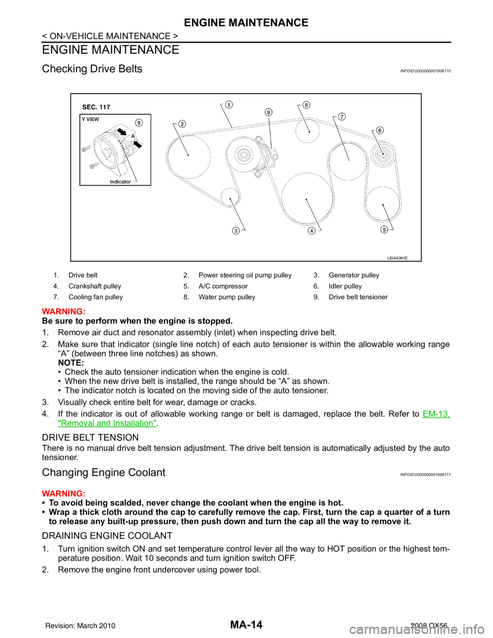
Checking Drive BeltsINFOID:0000000001606170
WARNING:
Be sure to perform when the engine is stopped.
1. Remove air duct and resonator assembly (inlet) when inspecting drive belt.
2. Make sure that indicator (single line notch) of each auto tensioner is within the allowable working range“A” (between three line notches) as shown.
NOTE:
• Check the auto tensioner indication when the engine is cold.
• When the new drive belt is installed, the range should be “A” as shown.
• The indicator notch is located on the moving side of the auto tensioner.
3. Visually check entire belt for wear, damage or cracks.
4. If the indicator is out of allowable working range or belt is damaged, replace the belt. Refer to EM-13,
"Removal and Installation".
DRIVE BELT TENSION
There is no manual drive belt tension adjustment. The driv e belt tension is automatically adjusted by the auto
tensioner.
Changing Engine CoolantINFOID:0000000001606171
WARNING:
• To avoid being scalded, never change the coolant when the engine is hot.
• Wrap a thick cloth around the cap to carefully remove the cap. First, turn the cap a quarter of a turn
to release any built-up pressure, th en push down and turn the cap all the way to remove it.
DRAINING ENGINE COOLANT
1. Turn ignition switch ON and set temperature control lever all the way to HOT position or the highest tem-
perature position. Wait 10 seconds and turn ignition switch OFF.
2. Remove the engine front undercover using power tool.
1. Drive belt 2. Power steering oil pump pulley 3. Generator pulley
4. Crankshaft pulley 5. A/C compressor6. Idler pulley
7. Cooling fan pulley 8. Water pump pulley 9. Drive belt tensioner
LBIA0391E
Revision: March 2010 2008 QX56
Page 2614 of 4083
MA-16
< ON-VEHICLE MAINTENANCE >
ENGINE MAINTENANCE
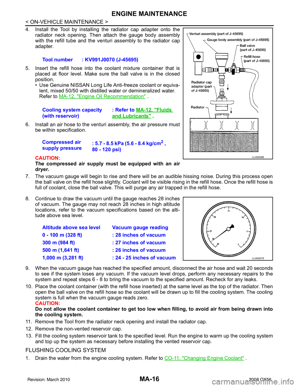
4. Install the Tool by installing the radiator cap adapter onto theradiator neck opening. Then attach the gauge body assembly
with the refill tube and the venturi assembly to the radiator cap
adapter.
5. Insert the refill hose into the coolant mixture container that is placed at floor level. Make sure the ball valve is in the closed
position.
• Use Genuine NISSAN Long Life Anti-freeze coolant or equiva-
lent, mixed 50/50 with distilled water or demineralized water.
Refer to MA-12, "
Engine Oil Recommendation" .
6. Install an air hose to the venturi assembly, the air pressure must be within specification.
CAUTION:
The compressed air supply must be equipped with an air
dryer.
7. The vacuum gauge will begin to rise and there will be an audible hissing noise. During this process open the ball valve on the refill hose slightly. Coolant will be vi sible rising in the refill hose. Once the refill hose is
full of coolant, close the ball valve. This will purge any air trapped in the refill hose.
8. Continue to draw the vacuum until the gauge reaches 28 inches of vacuum. The gauge may not reach 28 inches in high altitude
locations, refer to the vacuum specifications based on the alti-
tude above sea level.
9. When the vacuum gauge has reached the specifi ed amount, disconnect the air hose and wait 20 seconds
to see if the system loses any vacuum. If the vacuum level drops, perform any necessary repairs to the
system and repeat steps 6 - 8 to bring the vacuum to the specified amount. Recheck for any leaks.
10. Place the coolant container (with the refill hose insert ed) at the same level as the top of the radiator. Then
open the ball valve on the refill hose so the coolant will be drawn up to fill the cooling system. The cooling
system is full when the vacuum gauge reads zero.
CAUTION:
Do not allow the coolant container to get too low when filling, to avoid air from being drawn into
the cooling system.
11. Remove the Tool from the radiator neck opening and install the radiator cap.
12. Remove the non-vented reservoir cap.
13. Fill the cooling system reservoir tank to the specif ied level. Run the engine to warm up the cooling system
and top up the system as necessary before installing the vented reservoir cap.
FLUSHING COOLING SYSTEM
1. Drain the water from the engine cooling system. Refer to CO-11, "Changing Engine Coolant" .
Tool number : KV991J0070 (J-45695)
Cooling system capacity
(with reservoir)
: Refer to
MA-12, "
Fluids
and Lubricants" .
Compressed air
supply pressure : 5.7 - 8.5 kPa (5.6 - 8.4 kg/cm
2 ,
80 - 120 psi)
LLIA0058E
Altitude above sea level Vacuum gauge reading
0 - 100 m (328 ft) : 28 inches of vacuum
300 m (984 ft) : 27 inches of vacuum
500 m (1,641 ft) : 26 inches of vacuum
1,000 m (3,281 ft) : 24 - 25 inches of vacuum
LLIA0057E
Revision: March 2010 2008 QX56
Page 2617 of 4083
ENGINE MAINTENANCEMA-19
< ON-VEHICLE MAINTENANCE >
C
DE
F
G H
I
J
K L
M B
MA
N
O A
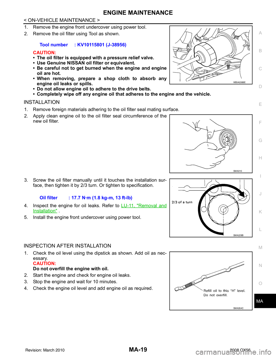
1. Remove the engine front undercover using power tool.
2. Remove the oil filter using Tool as shown.
CAUTION:
• The oil filter is equipped with a pressure relief valve.
• Use Genuine NISSAN oil filter or equivalent.
• Be careful not to get burned when the engine and engine
oil are hot.
• When removing, prepare a s hop cloth to absorb any
engine oil leaks or spills.
• Do not allow engine oil to adhere to the drive belts.
• Completely wipe off any engine oil that adheres to the engine and the vehicle.
INSTALLATION
1. Remove foreign materials adhering to the oil filter seal mating surface.
2. Apply clean engine oil to the oil filter seal circumference of the
new oil filter.
3. Screw the oil filter manually unt il it touches the installation sur-
face, then tighten it by 2/3 turn. Or tighten to specification.
4. Inspect the engine for oil leaks. Refer to LU-11, "
Removal and
Installation" .
5. Install the engine front undercover using power tool.
INSPECTION AFTER INSTALLATION
1. Check the oil level using the dipstick as shown. Add oil as nec- essary.
CAUTION:
Do not overfill th e engine with oil.
2. Start the engine and check for engine oil leaks.
3. Stop the engine and wait for 10 minutes.
4. Check the engine oil level and add engine oil as required. Tool number : KV10115801 (J-38956)
WBIA0388E
SMA010
Oil filter : 17.7 N·m (1.8 kg-m, 13 ft-lb)
SMA229B
SMA954C
Revision: March 2010
2008 QX56
Page 2618 of 4083
MA-20
< ON-VEHICLE MAINTENANCE >
ENGINE MAINTENANCE
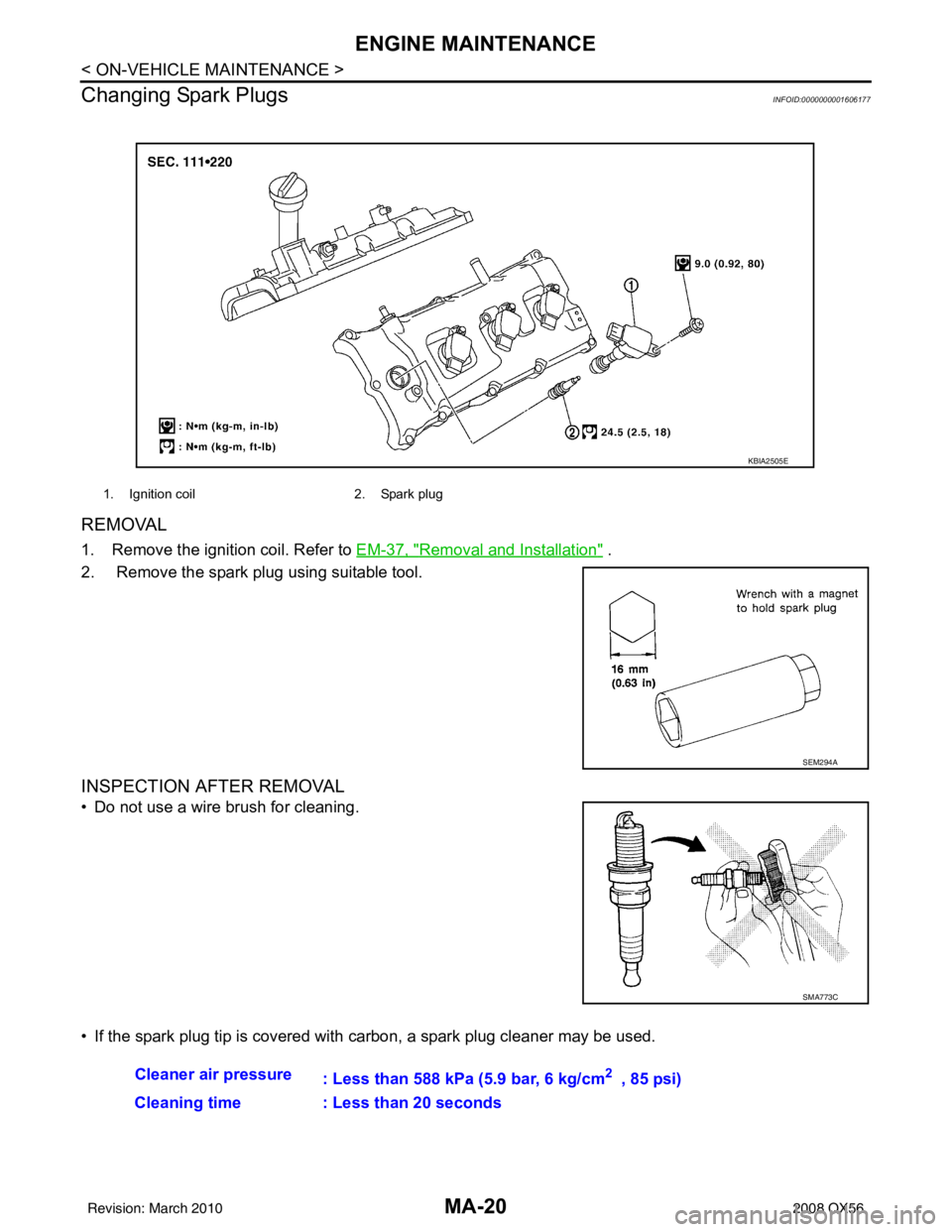
Changing Spark Plugs
INFOID:0000000001606177
REMOVAL
1. Remove the ignition coil. Refer to EM-37, "Removal and Installation" .
2. Remove the spark plug using suitable tool.
INSPECTION AFTER REMOVAL
• Do not use a wire brush for cleaning.
• If the spark plug tip is covered with carbon, a spark plug cleaner may be used.
1. Ignition coil 2. Spark plug
KBIA2505E
SEM294A
SMA773C
Cleaner air pressure
: Less than 588 kPa (5.9 bar, 6 kg/cm2 , 85 psi)
Cleaning time : Less than 20 seconds
Revision: March 2010 2008 QX56
Page 2646 of 4083
MWI
MWI-1
DRIVER INFORMATION & MULTIMEDIA
C
DE
F
G H
I
J
K L
M B
SECTION MWI
A
O P
CONTENTS
METER, WARNING LAMP & INDICATOR
BASIC INSPECTION ....... .............................4
DIAGNOSIS AND REPAIR WORKFLOW ..... .....4
Work Flow ........................................................... ......4
FUNCTION DIAGNOSIS ...............................5
METER SYSTEM ............................................ .....5
METER SYSTEM .........................................................5
METER SYSTEM : System Diagram ........................5
METER SYSTEM : System Description ....................5
METER SYSTEM : Arrangem ent of Combination
Meter ................................................................... ......
6
METER SYSTEM : Component Parts Location ........7
METER SYSTEM : Component Description ....... ......7
SPEEDOMETER ..........................................................8
SPEEDOMETER : System Diagram ................... ......8
SPEEDOMETER : System Description .....................8
SPEEDOMETER : Component Parts Location .........9
SPEEDOMETER : Component Description ........ ......9
TACHOMETER ...................................................... ......9
TACHOMETER : System Diagram ...........................9
TACHOMETER : System De scription .....................10
TACHOMETER : Component Parts Location ..... ....10
TACHOMETER : Component Description ..............10
ENGINE COOLANT TEMPERATURE GAUGE .... ....10
ENGINE COOLANT TEMPERATURE GAUGE :
System Diagram ......................................................
11
ENGINE COOLANT TEMPERATURE GAUGE :
System Description .................................................
11
ENGINE COOLANT TEMPERATURE GAUGE :
Component Parts Location ......................................
11
ENGINE COOLANT TEMPERATURE GAUGE :
Component Description ...........................................
12
FUEL GAUGE ........................................................ ....12
FUEL GAUGE : System Diagram ...........................12
FUEL GAUGE : System Description .......................12
FUEL GAUGE : Component Parts Location ...........12
FUEL GAUGE : Component Description ............. ....13
ENGINE OIL PRESSURE GAUGE ............................13
ENGINE OIL PRESSURE GAUGE : System Dia-
gram .................................................................... ....
13
ENGINE OIL PRESSURE GAUGE : System De-
scription ...................................................................
13
ENGINE OIL PRESSURE GAUGE : Component
Parts Location ..........................................................
14
ENGINE OIL PRESSURE GAUGE : Component
Description ...............................................................
14
VOLTAGE GAUGE ................................................ ....14
VOLTAGE GAUGE : System Diagram ....................15
VOLTAGE GAUGE : System Description ................15
VOLTAGE GAUGE : Component Parts Location ....15
VOLTAGE GAUGE : Component Description .........16
ODO/TRIP METER ................................................. ....16
ODO/TRIP METER : System Diagram ....................16
ODO/TRIP METER : System Description ................16
ODO/TRIP METER : Component Parts Location ....16
ODO/TRIP METER : Component Description .........17
SHIFT POSITION INDICATOR .............................. ....17
SHIFT POSITION INDICATOR : System Diagram ....17
SHIFT POSITION INDICATOR : System Descrip-
tion ...........................................................................
17
SHIFT POSITION INDICATOR : Component
Parts Location ..........................................................
18
SHIFT POSITION INDICATOR : Component De-
scription ............................................................... ....
18
WARNING LAMPS/INDICATOR LAMPS .............. ....18
WARNING LAMPS/INDICATOR LAMPS : System
Diagram ............................................................... ....
18
WARNING LAMPS/INDICATOR LAMPS : System
Description ........................................................... ....
19
WARNING LAMPS/INDICATOR LAMPS : Com-
ponent Parts Location ..............................................
19
WARNING LAMPS/INDICATOR LAMPS : Com-
ponent Description ...................................................
19
Revision: March 2010 2008 QX56
Page 2647 of 4083

MWI-2
INFORMATION DISPLAY .........................................19
INFORMATION DISPLAY : System Diagram .........20
INFORMATION DISPLAY : System Description ....20
INFORMATION DISPLAY : Component Parts Lo-
cation ................................................................... ...
21
INFORMATION DISPLAY : Component Descrip-
tion ....................................................................... ...
21
COMPASS .........................................................22
Description ........................................................... ...22
DIAGNOSIS SYSTEM (METER) .......................24
Diagnosis Description .......................................... ...24
CONSULT-III Function (METER/M&A) ................ ...25
COMPONENT DIAGNOSIS ........................28
DTC U1000 CAN COMMUNICATION ............ ...28
DTC Logic ............................................................ ...28
Diagnosis Procedure .............................................28
DTC B2205 VEHICLE SPEED CIRCUIT ...........29
Description ........................................................... ...29
DTC Logic ...............................................................29
Diagnosis Procedure .............................................29
POWER SUPPLY AND GROUND CIRCUIT .....30
COMBINATION METER ........................................ ...30
COMBINATION METER : Diagnosis Procedure ....30
BCM (BODY CONTROL MODULE) ...................... ...30
BCM (BODY CONTROL MODULE) : Diagnosis
Procedure ...............................................................
31
IPDM E/R (INTELLIGENT POWER DISTRIBU-
TION MODULE ENGINE ROOM) .......................... ...
31
IPDM E/R (INTELLIGENT POWER DISTRIBU-
TION MODULE ENGINE ROOM) : Diagnosis Pro-
cedure .....................................................................
31
FUEL LEVEL SENSOR SIGNAL CIRCUIT .......33
Description ........................................................... ...33
Component Function Check ...................................33
Diagnosis Procedure .............................................33
Component Inspection ............................................34
OIL PRESSURE SWITCH SIGNAL CIRCUIT ...35
Description ..............................................................35
Component Function Check ...................................35
Diagnosis Procedure ..............................................35
Component Inspection ............................................35
PARKING BRAKE SWITCH SIGNAL CIR-
CUIT ...................................................................
36
Description ........................................................... ...36
Component Function Check ...................................36
Diagnosis Procedure ..............................................36
Component Inspection ............................................36
WASHER LEVEL SWITCH SIGNAL CIRCUIT ...37
Description ........................................................... ...37
Diagnosis Procedure ............................................ ...37
Component Inspection ............................................37
COMPASS .........................................................38
Wiring Diagram .................................................... ...38
CLOCK ..............................................................40
Wiring Diagram .................................................... ...40
ECU DIAGNOSIS .......................................42
COMBINATION METER ................................. ...42
Reference Value .................................................. ...42
Wiring Diagram .......................................................44
Fail Safe ..................................................................61
DTC Index ...............................................................62
BCM (BODY CONTROL MODULE) ..................64
Reference Value .................................................. ...64
Terminal Layout ......................................................64
Physical Values .......................................................64
Wiring Diagram .......................................................64
DTC Inspection Priority Chart ...............................64
DTC Index ..............................................................64
IPDM E/R (INTELLIGENT POWER DISTRI-
BUTION MODULE ENGINE ROOM) .................
65
Reference Value .................................................. ...65
Terminal Layout ......................................................65
Physical Values .......................................................65
Wiring Diagram .......................................................65
Fail Safe .................................................................65
DTC Index ..............................................................65
SYMPTOM DIAGNOSIS ............................66
THE FUEL GAUGE POINTER DOES NOT
MOVE .............................................................. ...
66
Description ........................................................... ...66
Diagnosis Procedure ...............................................66
THE FUEL GAUGE POINTER DOES NOT
MOVE TO "F" WHEN REFUELING ..................
67
Description ........................................................... ...67
Diagnosis Procedure ...............................................67
THE OIL PRESSURE WARNING LAMP
DOES NOT TURN ON .................................... ...
68
Description ........................................................... ...68
Diagnosis Procedure ...............................................68
THE OIL PRESSURE WARNING LAMP
DOES NOT TURN OFF .................................. ...
69
Description ........................................................... ...69
Diagnosis Procedure ...............................................69
THE PARKING BRAKE RELEASE WARNING
CONTINUES DISPLAYING, OR DOES NOT
DISPLAY ............................................................
70
Description ........................................................... ...70
Diagnosis Procedure ...............................................70
Revision: March 2010 2008 QX56
Page 2652 of 4083
MWI
METER SYSTEMMWI-7
< FUNCTION DIAGNOSIS >
C
DE
F
G H
I
J
K L
M B A
O P
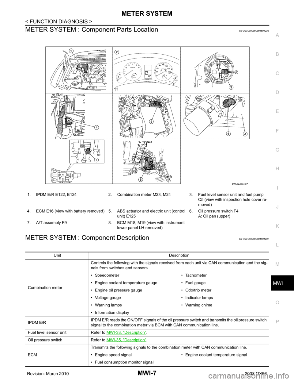
METER SYSTEM : Com ponent Parts LocationINFOID:0000000001691236
METER SYSTEM : Component DescriptionINFOID:0000000001691237
1. IPDM E/R E122, E124 2. Combination meter M23, M24 3. Fuel level sensor unit and fuel pump
C5 (view with inspection hole cover re-
moved)
4. ECM E16 (view with battery removed) 5. ABS actuator and electric unit (control unit) E1256. Oil pressure switch F4
A: Oil pan (upper)
7. A/T assembly F9 8. BCM M18, M19 (view with instrument
lower panel LH removed)
AWNIA0201ZZ
Unit Description
Combination meter Controls the following with the signals received from each unit via CAN communication and the sig-
nals from switches and sensors.
• Speedometer
• Tachometer
• Engine coolant temperature gauge • Fuel gauge
• Engine oil pressure gauge • Odo/trip meter
• Voltage gauge • Indicator lamps
• Warning lamps • Warning chime
• Information display
IPDM E/R IPDM E/R reads the ON/OFF signals of the oil pressure switch and transmits the oil pressure switch
signal to the combination meter via BCM with CAN communication line.
Fuel level sensor unit Refer to MWI-33, "
Description".
Oil pressure switch Refer to MWI-35, "
Description".
ECM Transmits the following signals to the combination meter with CAN communication line.
• Engine speed signal
• Engine coolant temperature signal
• Fuel consumption monitor signal
Revision: March 2010 2008 QX56