2008 INFINITI QX56 differential
[x] Cancel search: differentialPage 1294 of 4083
![INFINITI QX56 2008 Factory Service Manual DLN-264
< DISASSEMBLY AND ASSEMBLY >[REAR FINAL DRIVE: R230]
REAR FINAL DRIVE
10. Apply anti-corrosive oil to the threads of the drive pinion and the
seating surface of the new drive pinion lock nut. INFINITI QX56 2008 Factory Service Manual DLN-264
< DISASSEMBLY AND ASSEMBLY >[REAR FINAL DRIVE: R230]
REAR FINAL DRIVE
10. Apply anti-corrosive oil to the threads of the drive pinion and the
seating surface of the new drive pinion lock nut.](/manual-img/42/57030/w960_57030-1293.png)
DLN-264
< DISASSEMBLY AND ASSEMBLY >[REAR FINAL DRIVE: R230]
REAR FINAL DRIVE
10. Apply anti-corrosive oil to the threads of the drive pinion and the
seating surface of the new drive pinion lock nut. Then adjust the
drive pinion lock nut tightening torque using Tool A, and check
the drive pinion bearing preload torque using Tool B.
CAUTION:
• Do not reuse drive pinion lock nut.
• Apply anti-corrosive oil to the threads of the drive pinionand the seating surface of the new drive pinion lock nut.
• Adjust the drive pinion lock nut tightening torque to the
lower limit first. Do not exceed the drive pinion lock nut
specified torque. Refer to "COMPONENTS".
• If the drive pinion bearin g preload torque exceeds the
specified value, replace collap sible spacer and tighten it
again to adjust. Do not loosen drive pinion lock nut to
adjust the drive pinion bearing preload torque.
• After adjustment, rotate dri ve pinion back and forth 2 to 3
times to check for unusual noise, rotation malfunction,
and other malfunctions.
11. Check companion flange runout. Refer to "Companion Flange Runout".
12. Install the differential case assembly. Refer to "Differential Assembly".
Differential Assembly
1. Install side gear thrust washers with the same thickness as the ones installed prior to disassembly, or reinstall the old ones on
the side gears.
2. Install the side gears and side gear thrust washers into the dif- ferential case.
CAUTION:
Make sure that the circular clip is installed to side gears.
3. Install the pinion mate thrust washers to the two pinion mate gears. Then install the pinion mate gears with the pinion mate
thrust washers by aligning them in diagonally opposite positions
and rotating them into the differential case.Tool number A: KV40104000 ( — )
B: ST3127S000 (J-25765-A)
Drive pinion bearing preload torque: 1.77 - 2.64 N·m (0.18 - 0.26 kg-m, 16 - 23 in-lb)
WDIA0379E
SDIA0193J
SDIA2025E
Revision: March 2010 2008 QX56
Page 1295 of 4083
![INFINITI QX56 2008 Factory Service Manual REAR FINAL DRIVEDLN-265
< DISASSEMBLY AND ASSEMBLY > [REAR FINAL DRIVE: R230]
C
EF
G H
I
J
K L
M A
B
DLN
N
O P
4. Align the lock pin hole on the differential case with the lock pin hole on the pinion INFINITI QX56 2008 Factory Service Manual REAR FINAL DRIVEDLN-265
< DISASSEMBLY AND ASSEMBLY > [REAR FINAL DRIVE: R230]
C
EF
G H
I
J
K L
M A
B
DLN
N
O P
4. Align the lock pin hole on the differential case with the lock pin hole on the pinion](/manual-img/42/57030/w960_57030-1294.png)
REAR FINAL DRIVEDLN-265
< DISASSEMBLY AND ASSEMBLY > [REAR FINAL DRIVE: R230]
C
EF
G H
I
J
K L
M A
B
DLN
N
O P
4. Align the lock pin hole on the differential case with the lock pin hole on the pinion mate shaft, and install the pinion mate shaft.
5. Measure the side gear end play. If necessary, select the appro- priate side gear thrust washers. Refer to DLN-268, "
Inspection
and Adjustment".
6. Drive a new lock pin into the pinion mate shaft until it is flush with the differential case using suitable tool.
CAUTION:
Do not reuse lock pin.
7. Align the matching mark of the differential case with the mark of the drive gear, then place the drive gear onto the differential
case.
8. Apply thread locking sealant into the threaded holes of the drive gear and install the bolts.
• Use Genuine Medium Strength Thread Locking Sealant orequivalent. Refer to GI-15, "
Recommended Chemical Prod-
ucts and Sealants".
CAUTION:
Make sure the drive gear back and threaded holes are
clean.
9. Tighten the drive gear bolts to the specified torque. Refer to "COMPONENTS". After tightening the drive gear bolts to the
specified torque, tighten an additional 34 ° using Tool (A).
CAUTION:
• Always use Tool. Avoid tightening based on visual check alone.
• Tighten drive gear bolts in a crisscross pattern.
SDIA0195J
WDIA0131E
SDIA2593E
SDIA2594E
Tool number : KV10112100-A (BT-8653-A)
AWBIA0722ZZ
Revision: March 2010 2008 QX56
Page 1296 of 4083
![INFINITI QX56 2008 Factory Service Manual DLN-266
< DISASSEMBLY AND ASSEMBLY >[REAR FINAL DRIVE: R230]
REAR FINAL DRIVE
10. Press the side bearing inner races into the differential case
using Tools.
CAUTION:
Do not reuse side bearing inner ra INFINITI QX56 2008 Factory Service Manual DLN-266
< DISASSEMBLY AND ASSEMBLY >[REAR FINAL DRIVE: R230]
REAR FINAL DRIVE
10. Press the side bearing inner races into the differential case
using Tools.
CAUTION:
Do not reuse side bearing inner ra](/manual-img/42/57030/w960_57030-1295.png)
DLN-266
< DISASSEMBLY AND ASSEMBLY >[REAR FINAL DRIVE: R230]
REAR FINAL DRIVE
10. Press the side bearing inner races into the differential case
using Tools.
CAUTION:
Do not reuse side bearing inner race.
11. Install the differential case assembly with the side bearing outer races into the gear carrier.
12. Measure the side bearing preload torque. If necessary, select the appropriate side bearing adjusting washers. Refer to "Side
Bearing Preload Torque".
13. Insert the selected left and right side bearing adjusting washers in place between the side bearings and gear carrier.
14. Install the side bearing caps with the matching marks aligned and tighten the side bearing cap bolts to the specified torque.
Refer to "COMPONENTS".
15. Check and adjust the drive gear runout, tooth contact, drive gear to drive pinion backlash, and total pre- load torque. Refer to "Drive Gear Runout", "Tooth Contact", "Backlash" and "Total Preload Torque".
Recheck the above items.
16. Install the side flanges. Refer to "Side Flange". Tool number A: KV38100200 (J-26233)
B: ST33081000 ( — )
SPD353
SPD919
SPD924
SPD889
Revision: March 2010 2008 QX56
Page 1298 of 4083
![INFINITI QX56 2008 Factory Service Manual DLN-268
< SERVICE DATA AND SPECIFICATIONS (SDS) [REAR FINAL DRIVE: R230]
SERVICE DATA AND SPECIFICATIONS (SDS)
SERVICE DATA AND SPECIFICATIONS (SDS)
SERVICE DATA AND SPECIFICATIONS (SDS)
General Speci INFINITI QX56 2008 Factory Service Manual DLN-268
< SERVICE DATA AND SPECIFICATIONS (SDS) [REAR FINAL DRIVE: R230]
SERVICE DATA AND SPECIFICATIONS (SDS)
SERVICE DATA AND SPECIFICATIONS (SDS)
SERVICE DATA AND SPECIFICATIONS (SDS)
General Speci](/manual-img/42/57030/w960_57030-1297.png)
DLN-268
< SERVICE DATA AND SPECIFICATIONS (SDS) [REAR FINAL DRIVE: R230]
SERVICE DATA AND SPECIFICATIONS (SDS)
SERVICE DATA AND SPECIFICATIONS (SDS)
SERVICE DATA AND SPECIFICATIONS (SDS)
General SpecificationINFOID:0000000001604464
Inspection and AdjustmentINFOID:0000000001604465
DRIVE GEAR RUNOUT
Unit: mm (in)
SIDE GEAR CLEARANCE
Unit: mm (in)
PRELOAD TORQUE
Unit: N·m (kg-m, in-lb)
BACKLASH
Unit: mm (in)
COMPANION FLANGE RUNOUT
Unit: mm (in)
SELECTIVE PARTS
Applied model 4WD
VK56DE A/T
SE LE, SE*
Final drive model R230
Gear ratio 2.9373.357
Number of teeth (Drive gear/Drive pinion) 47 / 1647/14
Oil capacity (Approx.) 1.75 (3 3/4 US pt, 3 1/8 Imp pt)
Number of pinion gears 2
Drive pinion adjustment spacer type Collapsible
ItemRunout limit
Drive gear back face 0.05 (0.0020) or less
ItemSpecification
Side gear back clearance
(Clearance limit between side gear and differential case for adjusting
side gear backlash) 0.20 (0.0079) or less
(Each gear should rotate smoothly without excessive resis- tance during differential motion.)
Item Specification
Drive pinion bearing preload torque 1.77 − 2.64 N·m (0.18 − 0.26 kg−m, 16 − 23 in-lb)
Side bearing preload torque (reference value determined by drive
gear bolt pulling force) 0.20
− 0.52 N·m (0.02 − 0.05 kg −m, 2 − 4 in-lb)
Drive gear bolt pulling force (by spring gauge) 34.2 − 39.2 N (3.5 − 4.0 kg, 7.7 − 8.8 lb)
Total preload torque
(Total preload torque = drive pinion bearing preload torque + Side
bearing preload torque) 2.05
− 4.11 N·m (0.21 − 0.42 kg−m, 19 − 36 in-lb)
Item Specification
Drive gear to drive pinion gear 0.13 − 0.18 (0.0051 − 0.0070)
Item Runout limit
Outer side of the companion flange 0.08 (0.0031) or less
Revision: March 2010 2008 QX56
Page 1911 of 4083

EM-108
< SERVICE DATA AND SPECIFICATIONS (SDS)
SERVICE DATA AND SPECIFICATIONS (SDS)
SERVICE DATA AND SPECIFICATIONS (SDS)
SERVICE DATA AND SPECIFICATIONS (SDS)
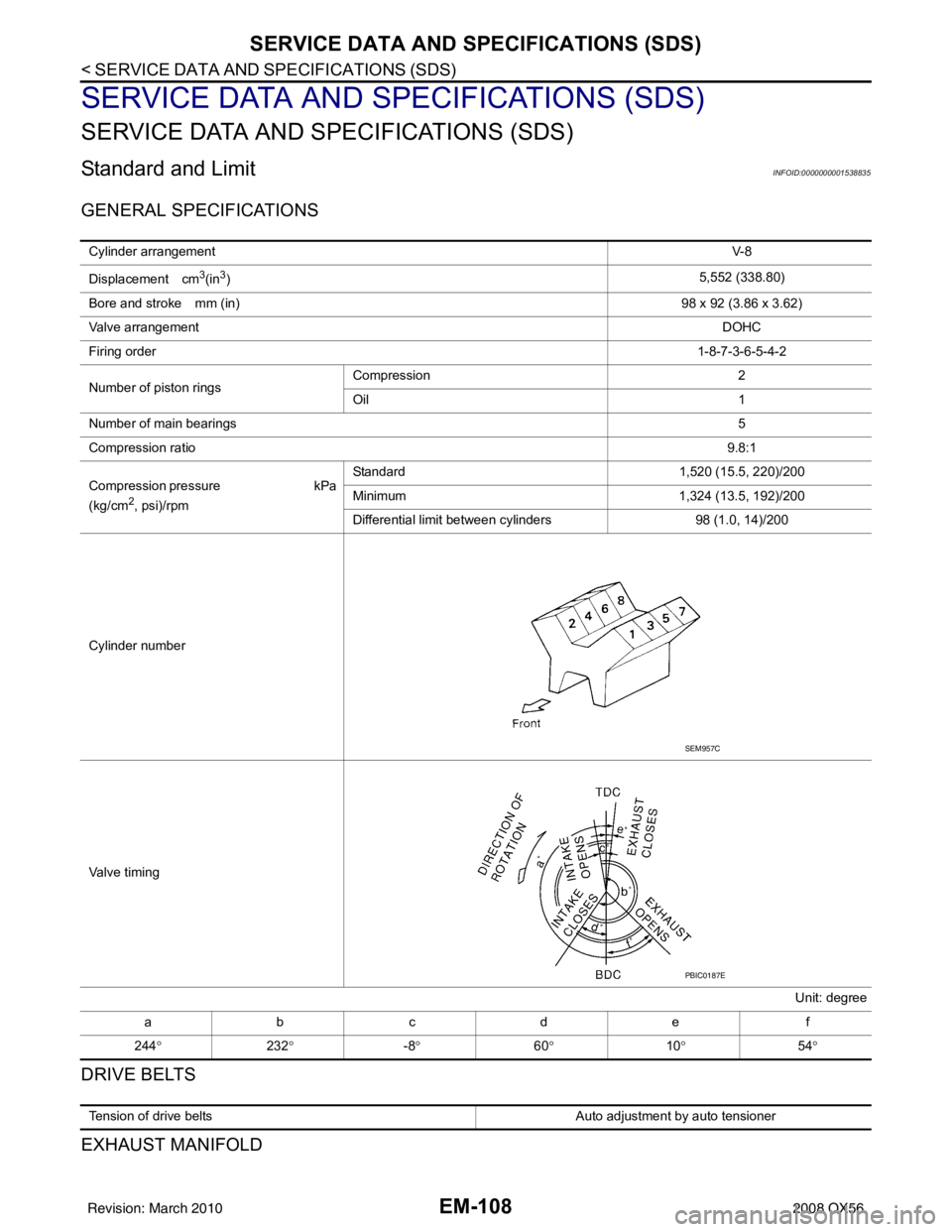
Standard and LimitINFOID:0000000001538835
GENERAL SPECIFICATIONS
DRIVE BELTS
EXHAUST MANIFOLD
Cylinder arrangementV- 8
Displacement cm
3(in3) 5,552 (338.80)
Bore and stroke mm (in) 98 x 92 (3.86 x 3.62)
Valve arrangement DOHC
Firing order 1-8-7-3-6-5-4-2
Number of piston rings Compression
2
Oil 1
Number of main bearings 5
Compression ratio 9.8:1
C o m p r e s s i o n p r e s s u r e k P a
(kg/cm
2, psi)/rpm Standard
1,520 (15.5, 220)/200
Minimum 1,324 (13.5, 192)/200
Differential limit between cylinders 98 (1.0, 14)/200
Cylinder number
Valve timing Unit: degree
abcde f
244 ° 232° -8° 60° 10° 54°
SEM957C
PBIC0187E
Tension of drive belts Auto adjustment by auto tensioner
Revision: March 2010 2008 QX56
Page 2159 of 4083

TERMINOLOGYGI-17
< HOW TO USE THIS MANUAL >
C
DE
F
G H
I
J
K L
M B
GI
N
O P
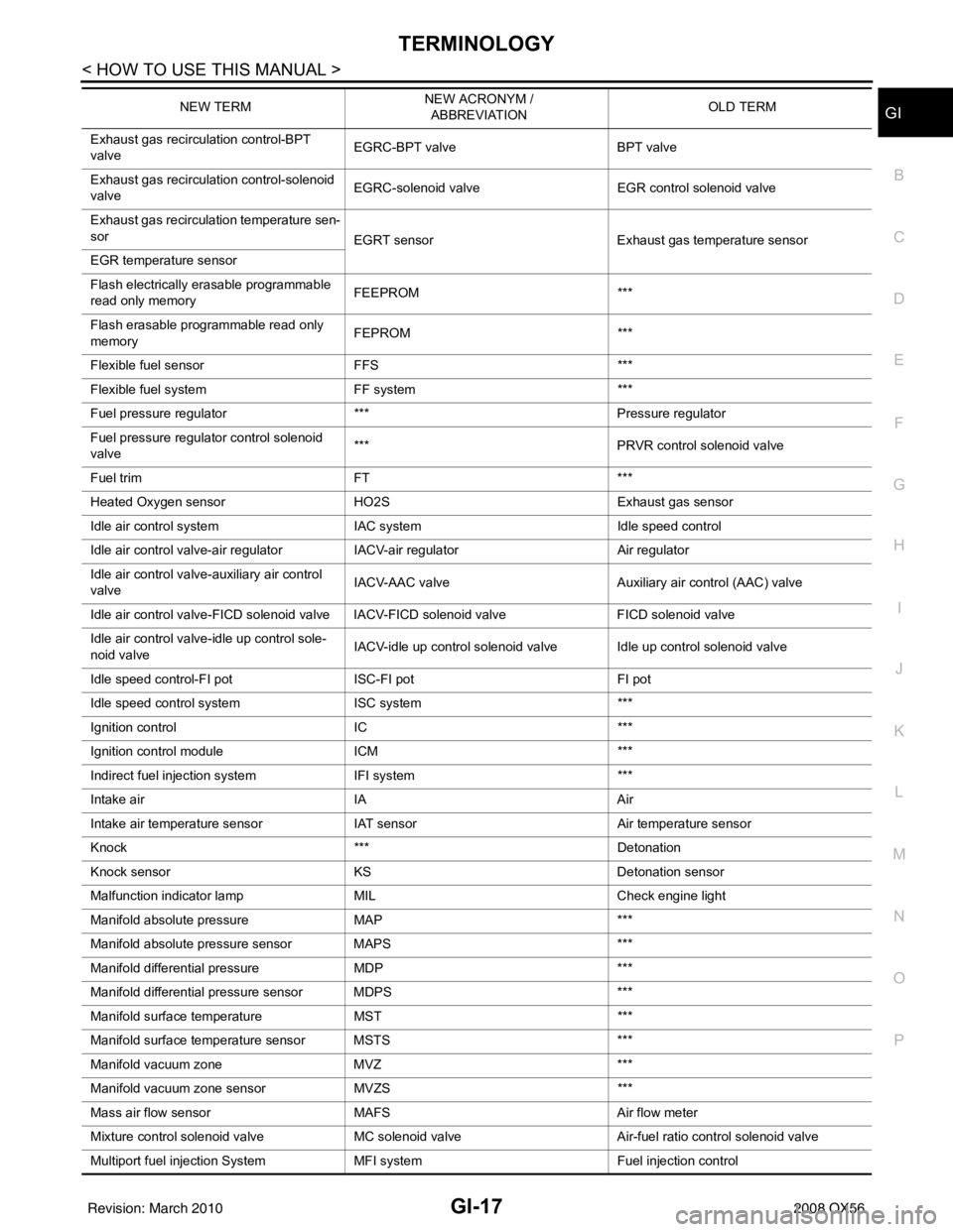
Exhaust gas recirculation control-BPT
valve EGRC-BPT valve
BPT valve
Exhaust gas recirculation control-solenoid
valve EGRC-solenoid valve
EGR control solenoid valve
Exhaust gas recirculation temperature sen-
sor EGRT sensorExhaust gas temperature sensor
EGR temperature sensor
Flash electrically erasable programmable
read only memory FEEPROM
***
Flash erasable programmable read only
memory FEPROM
***
Flexible fuel sensor FFS***
Flexible fuel system FF system***
Fuel pressure regulato r*** Pressure regulator
Fuel pressure regulator control solenoid
valve ***
PRVR control solenoid valve
Fuel trim FT***
Heated Oxygen sensor HO2S Exhaust gas sensor
Idle air control system IAC system Idle speed control
Idle air control valve-air regulato rIACV-air regulator Air regulator
Idle air control valve-auxiliary air control
valve IACV-AAC valve
Auxiliary air control (AAC) valve
Idle air control valve-FICD solenoid valve IACV-FICD solenoid valve FICD solenoid valve
Idle air control valve-idle up control sole-
noid valve IACV-idle up control solenoid valve Idle up control solenoid valve
Idle speed control-FI pot ISC-FI pot FI pot
Idle speed control system ISC system***
Ignition control IC***
Ignition control module ICM***
Indirect fuel injection system IFI system ***
Intake air IA Air
Intake air temperature sensor IAT sensor Air temperature sensor
Knock *** Detonation
Knock sensor KS Detonation sensor
Malfunction indicator lamp MIL Check engine light
Manifold absolute pressure MAP ***
Manifold absolute pressure sensor MAPS ***
Manifold differential pressure MDP ***
Manifold differential pressure sensor MDPS ***
Manifold su rface temperature MST ***
Manifold surface temperature sensor MSTS ***
Manifold vacuum zone MVZ ***
Manifold vacuum zone sensor MVZS***
Mass air flow sensor MAFS Air flow meter
Mixture control solenoid valve MC solenoid valveAir-fuel ratio control solenoid valve
Multiport fuel injection System MFI system Fuel injection control
NEW TERM
NEW ACRONYM /
ABBREVIATION OLD TERM
Revision: March 2010
2008 QX56
Page 2973 of 4083

NOISE, VIBRATION AND HARSHNESS (NVH) TROUBLESHOOTINGRAX-5
< SYMPTOM DIAGNOSIS >
CEF
G H
I
J
K L
M A
B
RAX
N
O P
SYMPTOM DIAGNOSIS
NOISE, VIBRATION AND HARSHN ESS (NVH) TROUBLESHOOTING
NVH Troubleshooting ChartINFOID:0000000001534575
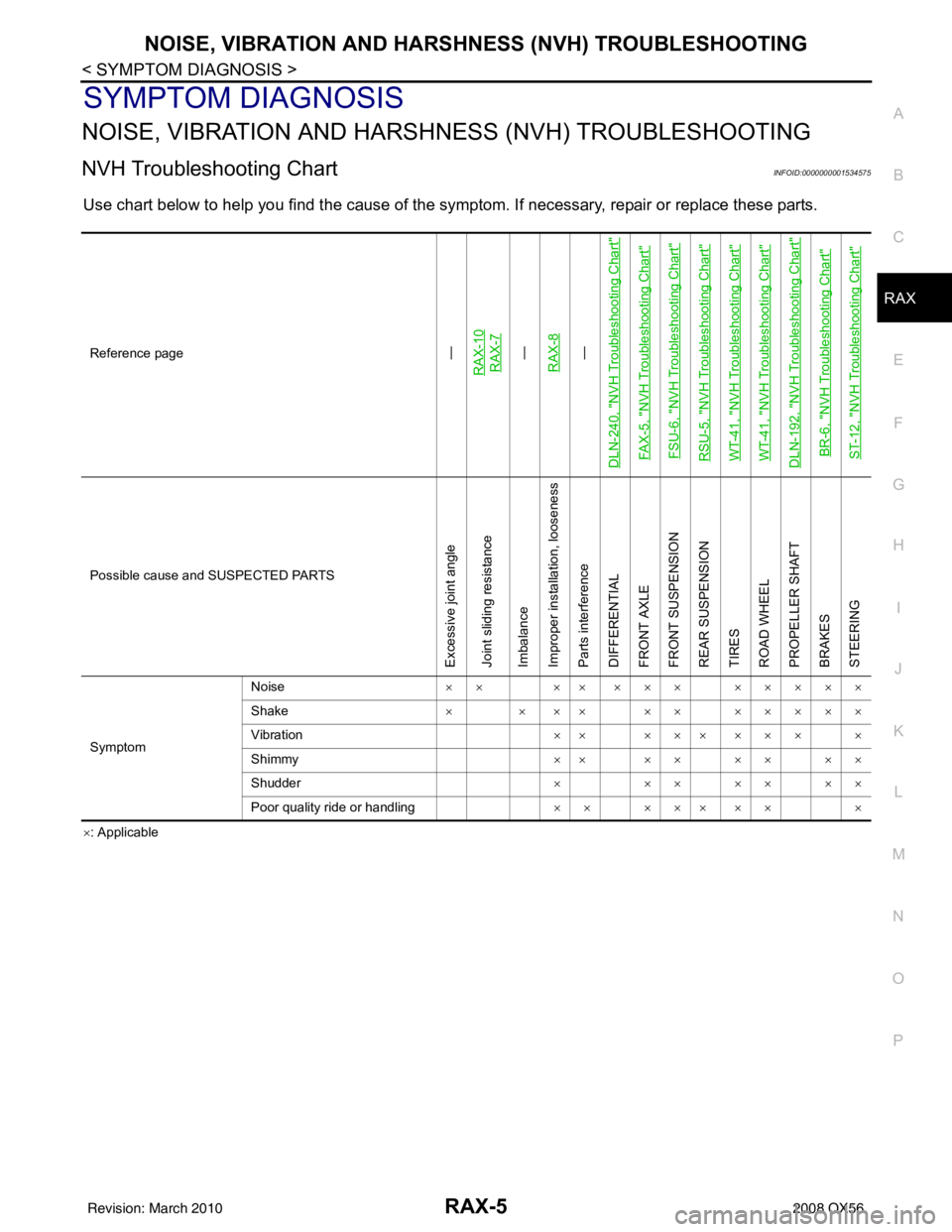
Use chart below to help you find the cause of the symptom. If necessary, repair or replace these parts.
×: Applicable
Reference page
—
RAX-10RAX-7—
RAX-8—
DLN-240, "
NVH Troubleshooting Chart
"
FAX-5, "
NVH Troubleshooting Chart
"
FSU-6, "
NVH Troubleshooting Chart
"
RSU-5, "
NVH Troubleshooting Chart
"
WT-41, "
NVH Troubleshooting Chart
"
WT-41, "
NVH Troubleshooting Chart
"
DLN-192, "
NVH Troubleshooting Chart
"
BR-6, "
NVH Troubleshooting Chart
"
ST-12, "
NVH Troubleshooting Chart
"
Possible cause and SUSPECTED PARTS
Excessive joint angle
Joint sliding resistance
Imbalance
Improper installation, looseness
Parts interference
DIFFERENTIAL
FRONT AXLE
FRONT SUSPENSION
REAR SUSPENSION
TIRES
ROAD WHEEL
PROPELLER SHAFT
BRAKES
STEERING
Symptom Noise
×× ×× ××× ×××××
Shake × × ×× ×× ×××××
Vibration ×× ××× ××× ×
Shimmy ×× ×× ×× ××
Shudder × ××××××
Poor quality ride or handling ×× ××× ×× ×
Revision: March 2010 2008 QX56
Page 3044 of 4083

NOISE, VIBRATION AND HARSHNESS (NVH) TROUBLESHOOTINGRSU-5
< SYMPTOM DIAGNOSIS >
C
DF
G H
I
J
K L
M A
B
RSU
N
O P
SYMPTOM DIAGNOSIS
NOISE, VIBRATION AND HARSHN ESS (NVH) TROUBLESHOOTING
NVH Troubleshooting ChartINFOID:0000000001534649
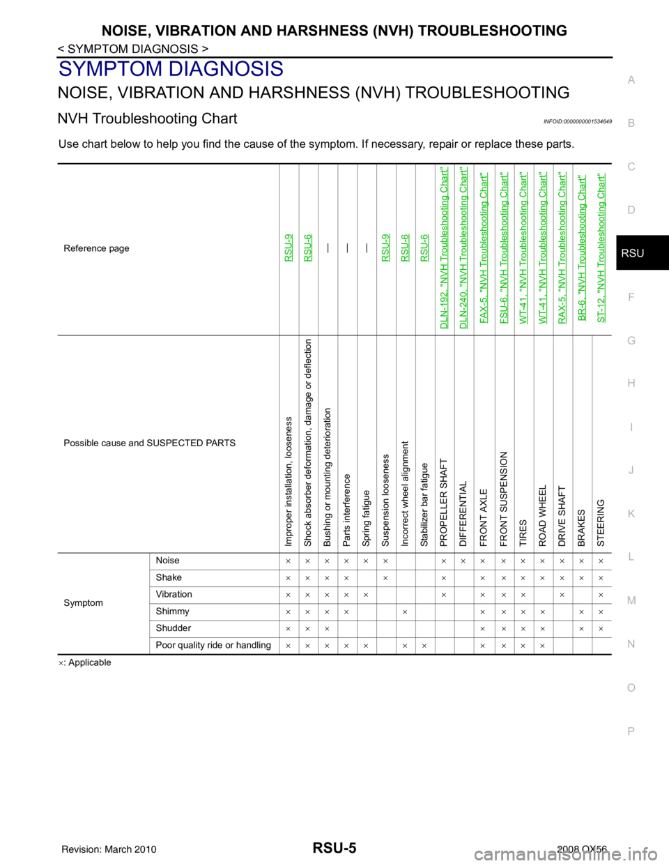
Use chart below to help you find the cause of the symptom. If necessary, repair or replace these parts.
×: ApplicableReference page
RSU-9RSU-6—
—
—
RSU-9RSU-6RSU-6
DLN-192, "
NVH Troubleshooting Chart
"
DLN-240, "
NVH Troubleshooting Chart
"
FAX-5, "
NVH Troubleshooting Chart
"
FSU-6, "
NVH Troubleshooting Chart
"
WT-41, "
NVH Troubleshooting Chart
"
WT-41, "
NVH Troubleshooting Chart
"
RAX-5, "
NVH Troubleshooting Chart
"
BR-6, "
NVH Troubleshooting Chart
"
ST-12, "
NVH Troubleshooting Chart
"
Possible cause and SUSPECTED PARTS
Improper installation, looseness
Shock absorber deformation, damage or deflection
Bushing or mounting deterioration
Parts interference
Spring fatigue
Suspension looseness
Incorrect wheel alignment
Stabilizer bar fatigue
PROPELLER SHAFT
DIFFERENTIAL
FRONT AXLE
FRONT SUSPENSION
TIRES
ROAD WHEEL
DRIVE SHAFT
BRAKES
STEERING
Symptom Noise
×××××× ××× ××××××
Shake ×××× × × × ××××××
Vibration ××××× × × ×× × ×
Shimmy ×××× × × ××× ××
Shudder ××× × ××× ××
Poor quality ride or handling ××××× ×× × ×××
Revision: March 2010 2008 QX56