2008 INFINITI QX56 display
[x] Cancel search: displayPage 3941 of 4083

WCS-64
< ECU DIAGNOSIS >
BCM (BODY CONTROL MODULE)
CONSULT displayFail-safeIntelligent Key
warning lamp ON Tire pressure
monitor warning lamp ON Reference page
No DTC is detected.
further testing
may be required. ————
U1000: CAN COMM CIRCUIT ———BCS-30
U1010: CONTROL UNIT (CAN) ———BCS-31
B2190: NATS ANTENNA AMP ———SEC-29
B2191: DIFFERENCE OF KEY ———SEC-32
B2192: ID DISCORD BCM-ECM ———SEC-33
B2193: CHAIN OF BCM-ECM ———SEC-35
B2552: INTELLIGENT KEY ———SEC-37
B2590: NATS MALFUNCTION ———SEC-38
C1704: LOW PRESSURE FL ———WT-31
C1705: LOW PRESSURE FR ———WT-31
C1706: LOW PRESSURE RR ———WT-31
C1707: LOW PRESSURE RL ———WT-31
C1708: [NO DATA] FL ———WT-14
C1709: [NO DATA] FR ———WT-14
C1710: [NO DATA] RR ———WT-14
C1711: [NO DATA] RL ———WT-14
C1712: [CHECKSUM ERR] FL ———WT-16
C1713: [CHECKSUM ERR] FR ———WT-16
C1714: [CHECKSUM ERR] RR ———WT-16
C1715: [CHECKSUM ERR] RL ———WT-16
C1716: [PRESSDATA ERR] FL ———WT-18
C1717: [PRESSDATA ERR] FR ———WT-18
C1718: [PRESSDATA ERR] RR ———WT-18
C1719: [PRESSDATA ERR] RL ———WT-18
C1720: [CODE ERR] FL ———WT-16
C1721: [CODE ERR] FR ———WT-16
C1722: [CODE ERR] RR ———WT-16
C1723: [CODE ERR] RL ———WT-16
C1724: [BATT VOLT LOW] FL ———WT-16
C1725: [BATT VOLT LOW] FR ———WT-16
C1726: [BATT VOLT LOW] RR ———WT-16
C1727: [BATT VOLT LOW] RL ———WT-16
C1729: VHCL SPEED SIG ERR ———WT-19
C1735: IGNITION SIGNAL ———WT-20
Revision: March 2010 2008 QX56
Page 3948 of 4083

WT-2
Low Tire Pressure Warning Lamp Flashes When
Ignition Switch Is Turned On ..................................
37
HAZARD WARNING LAMPS FLASH ...............38
Hazard Warning Lamps Flash When Ignition
Switch Is Turned On ............................................ ...
38
"TIRE PRESSURE" INFORMATION IN DIS-
PLAY UNIT DOES NOT EXIST .........................
39
"TIRE PRESSURE" Information in Display Unit
Does Not Exist ..................................................... ...
39
ID REGISTRATION CANNOT BE COMPLET-
ED ......................................................................
40
ID Registration Cannot Be Completed ................ ...40
NOISE, VIBRATION AND HARSHNESS
(NVH) TROUBLESHOOTING ......................... ...
41
NVH Troubleshooting Chart ................................ ...41
PRECAUTION .............................................42
PRECAUTIONS .............................................. ...42
Precaution for Supplemental Restraint System
(SRS) "AIR BAG" and "SEAT BELT PRE-TEN-
SIONER" .............................................................. ...
42
Precaution Necessary for Steering Wheel Rota-
tion After Battery Disconnect ..................................
42
PREPARATION ..........................................44
PREPARATION .............................................. ...44
Special Service Tool ............................................ ...44
Commercial Service Tool ........................................44
ON-VEHICLE MAINTENANCE ..................45
WHEEL ........................................................... ...45
Inspection ............................................................. ...45
ON-VEHICLE REPAIR ...............................46
WHEEL AND TIRE ASSEMBLY .................... ...46
Adjustment ........................................................... ...46
Rotation ...................................................................48
REMOVAL AND INSTALLATION ..............49
REMOVAL AND INSTALLATION .................. ...49
Transmitter (Pressure Sensor) ............................. ...49
SERVICE DATA AND SPECIFICATIONS
(SDS) .......... ................................. ...............
51
SERVICE DATA AND SPECIFICATIONS
(SDS) .............................................................. ...
51
Road Wheel ......................................................... ...51
Tire ..........................................................................51
Revision: March 2010 2008 QX56
Page 3950 of 4083
WT-4
< BASIC INSPECTION >
DIAGNOSIS AND REPAIR WORKFLOW
3.SELF-DIAGNOSIS
Perform SELF-DIAGNOSIS. Refer to WT-31, "
Self-Diagnosis (With CONSULT-III)" (with CONSULT-III) or WT-
32, "Self-Diagnosis (Without CONSULT-III)" (without CONSULT-III).
>> GO TO 4
4.SYMPTOM
Check for symptoms. Refer to WT-34, "
Symptom Table".
>> GO TO 5
5.MALFUNCTIONING PARTS
Repair or replace the applicable parts.
>> GO TO 6
6.DRIVE TEST
1. Perform a drive test.
2. Check the low tire pressure warning lamp.
>> GO TO 7
7.SELF-DIAGNOSIS
Perform SELF-DIAGNOSIS. Refer to WT-31, "
Self-Diagnosis (With CONSULT-III)" (with CONSULT-III) or WT-
32, "Self-Diagnosis (Without CONSULT-III)" (without CONSULT-III).
Are any DTC's displayed?
YES >> GO TO 5
NO >> INSPECTION END
Revision: March 2010 2008 QX56
Page 3952 of 4083
WT-6
< BASIC INSPECTION >
INSPECTION AND ADJUSTMENT
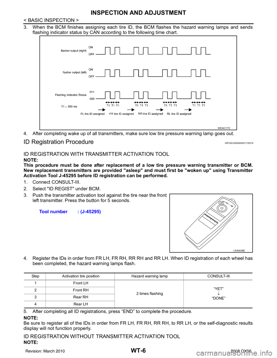
3. When the BCM finishes assigning each tire ID, the BCM flashes the hazard warning lamps and sendsflashing indicator status by CAN according to the following time chart.
4. After completing wake up of all transmitters, make sure low tire pressure warning lamp goes out.
ID Registration ProcedureINFOID:0000000001735374
ID REGISTRATION WITH TRANSMITTER ACTIVATION TOOL
NOTE:
This procedure must be done after replacement of a low tire pressure warning transmitter or BCM.
New replacement transmitters are provided "asleep" and must first be "woken up" using Transmitter
Activation Tool J-45295 before ID registration can be performed.
1. Connect CONSULT-III.
2. Select "ID REGIST" under BCM.
3. Push the transmitter activation tool against the tire near the front left transmitter. Press the button for 5 seconds.
4. Register the IDs in order from FR LH, FR RH, RR RH and RR LH. When ID registration of each wheel has been completed, the hazard warning lamps flash.
5. After completing all ID registrations, press “END” to complete the procedure.
NOTE:
Be sure to register all of the IDs in order from FR LH, FR RH, RR RH, to RR LH, or the self-diagnostic results
display will not function properly.
ID REGISTRATION WITHOUT TRANSMITTER ACTIVATION TOOL
NOTE:
WEIA0177E
Tool number : (J-45295)
LEIA0036E
Step Activation tire position Hazard warning lamp CONSULT-III
1 Front LH
2 times flashing “YET”
↓
“DONE”
2F
ro n t R H
3R ear R H
4 Rear LH
Revision: March 2010 2008 QX56
Page 3955 of 4083
TPMSWT-9
< FUNCTION DIAGNOSIS >
C
DF
G H
I
J
K L
M A
B
WT
N
O P
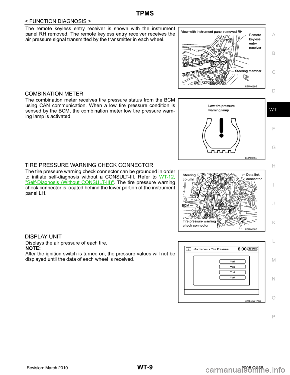
The remote keyless entry receiver is shown with the instrument
panel RH removed. The remote keyless entry receiver receives the
air pressure signal transmitted by the transmitter in each wheel.
COMBINATION METER
The combination meter receives tire pressure status from the BCM
using CAN communication. When a low tire pressure condition is
sensed by the BCM, the combination meter low tire pressure warn-
ing lamp is activated.
TIRE PRESSURE WARNING CHECK CONNECTOR
The tire pressure warning check connector can be grounded in order
to initiate self-diagnosis without a CONSULT-III. Refer to WT-12,
"Self-Diagnosis (Without CONSULT-III)". The tire pressure warning
check connector is located behind the lower portion of the instrument
panel LH.
DISPLAY UNIT
Displays the air pressure of each tire.
NOTE:
After the ignition switch is turned on, the pressure values will not be
displayed until the data of each wheel is received.
LEIA0069E
LEIA0055E
LEIA0068E
AWEIA0017GB
Revision: March 2010 2008 QX56
Page 3957 of 4083

DIAGNOSIS SYSTEM (BCM)WT-11
< FUNCTION DIAGNOSIS >
C
DF
G H
I
J
K L
M A
B
WT
N
O P
DIAGNOSIS SYSTEM (BCM)
CONSULT-III Function (BCM)INFOID:0000000001735378
CONSULT-III DIAGNOSTIC MODES
CONSULT-III can display each diagnostic item using the diagnostic test modes shown following.
DESCRIPTION
During driving, the tire pressure monitoring system receives the signal transmitted from the transmitter
installed in each wheel, and turns on the low tire pressure warning lamp when the tire pressure becomes low.
The control unit (BCM) for this system has pr essure judgement and self-diagnosis functions.
FUNCTION
When the tire pressure monitoring system detects low infl ation pressure or an internal malfunction, the low tire
pressure warning lamp in the combination meter comes on. The malfunction is indicated by the low tire pres-
sure warning lamp flashing.
CONSULT-III Application to Ti re Pressure Monitoring System
× : Applicable
– : Not applicable
Data Monitor Mode
Diagnostic mode Description
WORK SUPPORT Supports inspections and adjustments. Commands are transmitted to the BCM
for setting the status suitable for required operation, input/output signals are re-
ceived from the BCM and received data is displayed.
DATA MONITOR Displays BCM input/output data in real time.
ACTIVE TEST Operation of electrical loads can be checked by sending drive signal to them.
SELF-DIAG RESULTS Displays BCM self-diagnosis results.
CAN DIAG SUPPORT MNTR The result of transmit/receive diagnosis of CAN communication can be read.
ECU PART NUMBER BCM part number can be read.
CONFIGURATION Performs BCM configuration read/write functions.
ITEMSELF-DIAGNOSTIC RESULTS DATA MONITOR
Front - Left transmitter ××
Front - Right transmitter ××
Rear - Left transmitter ××
Rear - Right transmitter ××
Warning lamp —×
Vehicle speed ××
CAN Communication ××
MONITORCONDITION SPECIFICATION
VHCL SPEED Drive vehicle. Vehicle speed (km/h or MPH)
AIR PRESS FL
AIR PRESS FR
AIR PRESS RR
AIR PRESS RL • Drive vehicle for a few minutes.
Tire pressure (kPa or psi)
or
• Ignition switch ON and activation tool is transmitting activation signals.
Revision: March 2010 2008 QX56
Page 3958 of 4083
WT-12
< FUNCTION DIAGNOSIS >
DIAGNOSIS SYSTEM (BCM)
NOTE:
Before performing the self-diagnosis, be sure to register the ID, or the actual malfunction location may be different from that displayed on
CONSULT-III.
Self-Diagnosis (Without CONSULT-III)INFOID:0000000004291535
SELF-DIAGNOSTIC PROCEDURE (WITHOUT CONSULT-III)
1. Turn ignition switch ON.
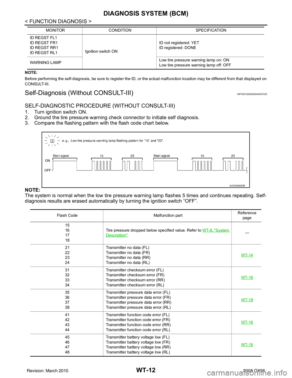
2. Ground the tire pressure warning check connector to initiate self diagnosis.
3. Compare the flashing pattern with the flash code chart below.
NOTE:
The system is normal when the low tire pressure warning lamp flashes 5 times and continues repeating. Self-
diagnosis results are erased automatically by turning the ignition switch “OFF”.
ID REGST FL1
ID REGST FR1
ID REGST RR1
ID REGST RL1Ignition switch ON ID not registered: YET
ID registered: DONE
WARNING LAMP Low tire pressure
warning lamp on: ON
Low tire pressure warning lamp off: OFF
MONITOR
CONDITION SPECIFICATION
Flash Code Malfunction partReference
page
15
16
17
18 Tire pressure dropped below specified value. Refer to
WT-8, "
System
Description". —
21
22
23
24 Transmitter no data (FL)
Transmitter no data (FR)
Transmitter no data (RR)
Transmitter no data (RL)
WT-14
31
32
33
34Transmitter chec
ksum error (FL)
Transmitter chec ksum error (FR)
Transmitter chec ksum error (RR)
Transmitter chec ksum error (RL) WT-16
35
36
37
38Transmitter pressure
data error (FL)
Transmitter pressure data error (FR)
Transmitter pressure data error (RR)
Transmitter pressure data error (RL) WT-18
41
42
43
44Transmitter function
code error (FL)
Transmitter function code error (FR)
Transmitter function code error (RR)
Transmitter function code error (RL) WT-16
45
46
47
48Transmitter battery voltage low (FL)
Transmitter battery voltage low (FR)
Transmitter battery voltage low (RR)
Transmitter battery voltage low (RL)
WT-16
ALEIA0050GB
Revision: March 2010
2008 QX56
Page 3960 of 4083
WT-14
< COMPONENT DIAGNOSIS >
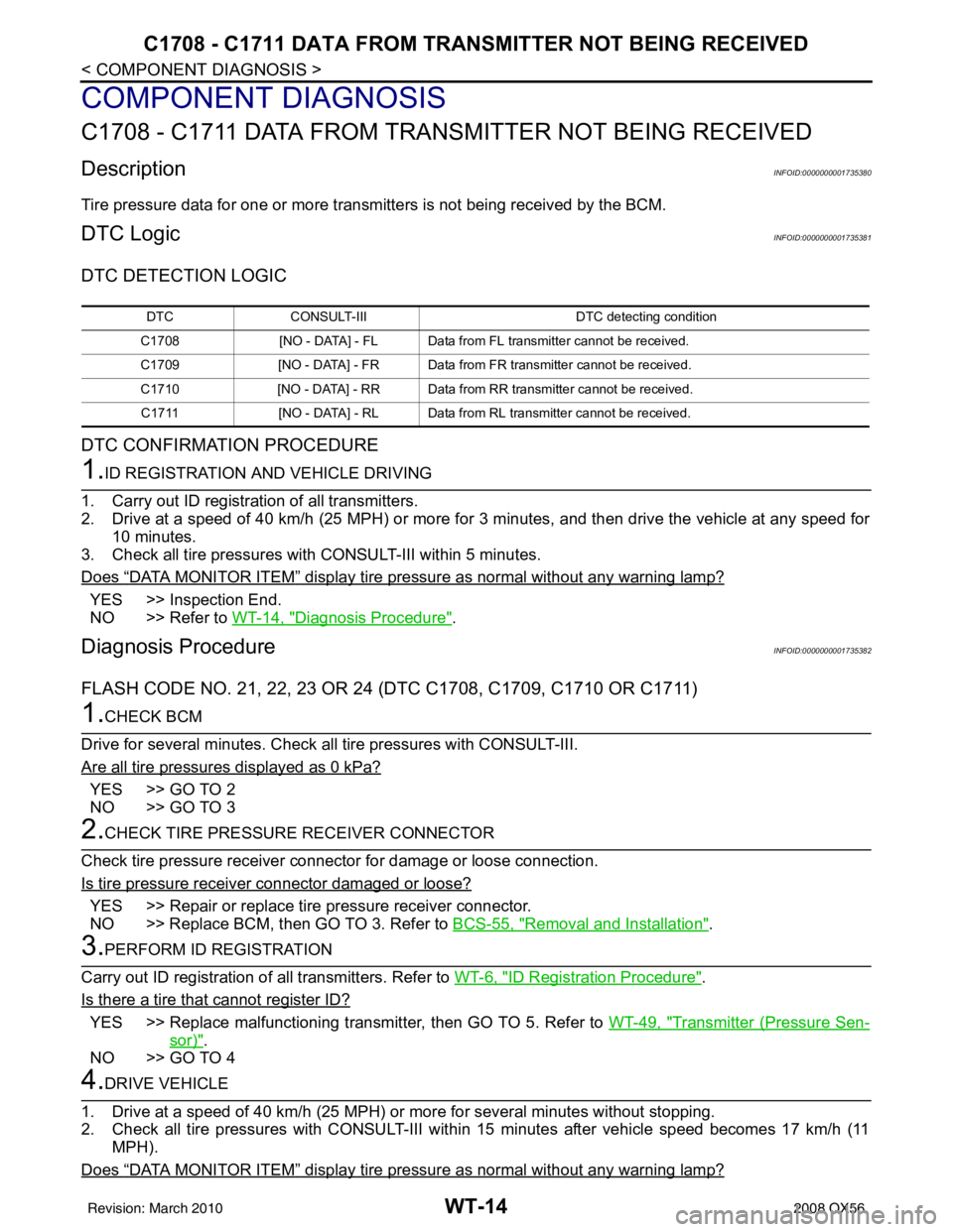
C1708 - C1711 DATA FROM TRANSMITTER NOT BEING RECEIVED
COMPONENT DIAGNOSIS
C1708 - C1711 DATA FROM TRANSMITTER NOT BEING RECEIVED
DescriptionINFOID:0000000001735380
Tire pressure data for one or more transmitters is not being received by the BCM.
DTC LogicINFOID:0000000001735381
DTC DETECTION LOGIC
DTC CONFIRMATION PROCEDURE
1.ID REGISTRATION AND VEHICLE DRIVING
1. Carry out ID registration of all transmitters.
2. Drive at a speed of 40 km/h (25 MPH) or more fo r 3 minutes, and then drive the vehicle at any speed for
10 minutes.
3. Check all tire pressures with CONSULT-III within 5 minutes.
Does
“DATA MONITOR ITEM” display tire pressure as normal without any warning lamp?
YES >> Inspection End.
NO >> Refer to WT-14, "
Diagnosis Procedure".
Diagnosis ProcedureINFOID:0000000001735382
FLASH CODE NO. 21, 22, 23 OR 24 (DTC C1708, C1709, C1710 OR C1711)
1.CHECK BCM
Drive for several minutes. Check all tire pressures with CONSULT-III.
Are all tire pressures displayed as 0 kPa?
YES >> GO TO 2
NO >> GO TO 3
2.CHECK TIRE PRESSURE RECEIVER CONNECTOR
Check tire pressure receiver connector for damage or loose connection.
Is tire pressure receiver connector damaged or loose?
YES >> Repair or replace tire pressure receiver connector.
NO >> Replace BCM, then GO TO 3. Refer to BCS-55, "
Removal and Installation".
3.PERFORM ID REGISTRATION
Carry out ID registration of all transmitters. Refer to WT-6, "
ID Registration Procedure".
Is there a tire that cannot register ID?
YES >> Replace malfunctioning transmitter, then GO TO 5. Refer to WT-49, "Transmitter (Pressure Sen-
sor)".
NO >> GO TO 4
4.DRIVE VEHICLE
1. Drive at a speed of 40 km/h (25 MPH) or more for several minutes without stopping.
2. Check all tire pressures with CONSULT-III within 15 minutes after vehicle speed becomes 17 km/h (11 MPH).
Does
“DATA MONITOR ITEM” display tire pressure as normal without any warning lamp?
DTC CONSULT-III DTC detecting condition
C1708 [NO - DATA] - FL Data from FL transmitter cannot be received.
C1709 [NO - DATA] - FR Data from FR transmitter cannot be received.
C1710 [NO - DATA] - RR Data from RR transmitter cannot be received.
C1711 [NO - DATA] - RL Data from RL transmitter cannot be received.
Revision: March 2010 2008 QX56