2008 INFINITI QX56 display
[x] Cancel search: displayPage 3847 of 4083

CONTROL UNITVTL-7
< ON-VEHICLE REPAIR >
C
DE
F
G H
J
K L
M A
B
VTL
N
O P
ON-VEHICLE REPAIR
CONTROL UNIT
Removal and InstallationINFOID:0000000001516603
A/C and AV SWITCH ASSEMBLY
Removal and Installation
The front A/C switch is integrated into the A/C and AV swit ch assembly in cluster lid C in the instrument panel.
Refer to AV-164, "
Removal and Installation".
A/C AUTO AMP.
Removal
1. Remove the display unit. Refer to AV-166, "Removal and Installation".
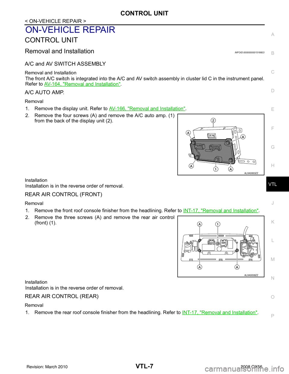
2. Remove the four screws (A) and remove the A/C auto amp. (1) from the back of the display unit (2).
Installation
Installation is in the reverse order of removal.
REAR AIR CONTROL (FRONT)
Removal
1. Remove the front roof console finisher from the headlining. Refer to INT-17, "Removal and Installation".
2. Remove the three screws (A) and remove the rear air control (front) (1).
Installation
Installation is in the reverse order of removal.
REAR AIR CONTROL (REAR)
Removal
1. Remove the rear roof console finisher from the headlining. Refer to INT-17, "Removal and Installation".
ALIIA0063ZZ
ALIIA0058ZZ
Revision: March 2010 2008 QX56
Page 3889 of 4083

WCS-12
< FUNCTION DIAGNOSIS >
DIAGNOSIS SYSTEM (METER)
DIAGNOSIS SYSTEM (METER)
Diagnosis DescriptionINFOID:0000000004872660
SELF-DIAGNOSIS MODE
The following items can be checked during Combination Meter Self-Diagnosis Mode.
• Gauge sweep and present gauge values.
• Illuminates all odometer/trip meters and A/T indicator segments.
• Illuminates all micro controlled lamps/LEDs regardless of switch position.
• Displays estimated present battery voltage.
• Displays seat belt buckle switch LH status.
OPERATION PROCEDURE
NOTE:
• Once entered, combination meter self-diagnosis mode will function with the ignition switch in ON or START.
Combination meter self-diagnosis mode will exit upon turning the ignition switch to OFF or ACC.
• If the diagnosis function is activated with trip A displa yed, the mileage on trip A is reset to 0000.0. (Trip B
operates the same way.)
To initiate combination meter self-diagnosis mode, refer to the following procedure.
1. Turn the ignition switch ON, while pressing the odometer/trip meter switch for 5 - 8 \
seconds. When the diagnosis function is activated, the odometer/trip meter will display tESt.
NOTE:
Check combination meter power supply and ground circuit when self-diagnosis mode of combination meter
does not start. Refer to MWI-30, "
COMBINATION METER : Diagnosis Procedure". Replace combination
meter if normal. Refer to MWI-76, "
Removal and Installation".
COMBINATION METER SELF-DIAGNOSIS MODE FUNCTIONS
To interpret combination meter self-diagnosis mode functions, refer to the following table.
EventOdometer Display Description of Test/Data Notes:
Odometer/trip meter A/B
switch held from 5 to 8
seconds (or until re-
leased) tESt
Initiating self-diagnosis mode
Switch released GAGE Performs sweep of all
gauges, then displays
present gauge values.Gauges sweep within 10 seconds
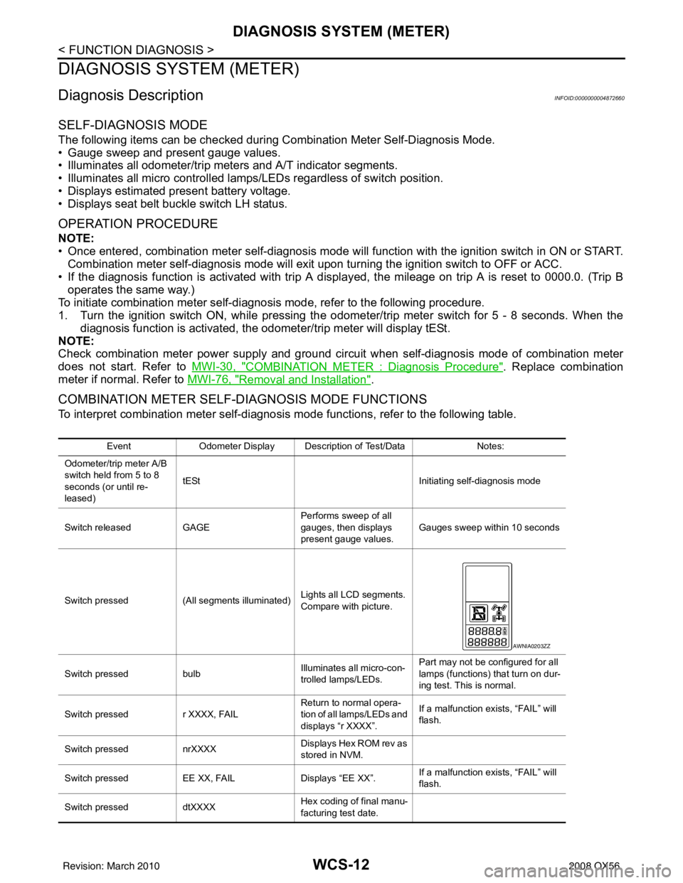
Switch pressed (All segments illuminated) Lights all LCD segments.
Compare with picture.
Switch pressed bulbIlluminates all micro-con-
trolled lamps/LEDs. Part may not be configured for all
lamps (functions) th
at turn on dur-
ing test. This is normal.
Switch pressed r XXXX, FAIL Return to normal opera-
tion of all lamps/LEDs and
displays “r XXXX”.If a malfunction exists, “FAIL” will
flash.
Switch pressed nrXXXX Displays Hex ROM rev as
stored in NVM.
Switch pressed EE XX, FAIL Displays “EE XX”.If a malfunction exists, “FAIL” will
flash.
Switch pressed dtXXXX Hex coding of final manu-
facturing test date.
AWNIA0203ZZ
Revision: March 2010
2008 QX56
Page 3890 of 4083

WCS
DIAGNOSIS SYSTEM (METER)WCS-13
< FUNCTION DIAGNOSIS >
C
DE
F
G H
I
J
K L
M B A
O P
CONSULT-III Function (METER/M&A)INFOID:0000000004872661
CONSULT-III can display each diagnostic item us ing the diagnostic test modes shown following.
SELF-DIAG RESULTS
Display Item List
Refer to MWI-62, "DTC Index".
DATA MONITOR
Display Item List
Switch pressed
(3 times) Sc1 XX through Epr XXDisplays 8 bit software
configuration value in Hex
format
Switch pressed 1nF XXDisplays 8-bit market info
value in Hex format. $31 = USA
$2A = Canada
Switch pressed
(3 times) cYL XX through tF N/A
Switch pressed XXXXX “Corrected” speed value
in hundredths of MPH.
Gauge indication may be
slightly higher. This is nor-
mal.Will display “-----” if message is not
received. Will display “99999” if
data received is invalid.
Switch pressed XXXXX “Corrected” speed value
in hundredths of KPH.
Gauge indication may be
slightly different. This is
normal.Will display “-----” if message is not
received. Will display “99999” if
data received is invalid.
Switch pressed t XXXX Tachometer value in
RPM. Gauge indication
may be higher at higher
RPM. This is normal.Will display “-----” if message is not
received.
Switch pressed F1XXXX Present fuel level A/D in-
put. This input represents
fuel sender input.000-009 = Short circuit
010-254 = Normal range
255 = Open circuit
Switch pressed F2XXX Present FLPS.010-254 = Normal range
Switch pressed XXXC Last temperature gauge
input value in degrees C.
Temperature gauge indi-
cates present tempera-
ture per indication
standard.Will display “---”C if
message is not
received.
Will display “999” if data received
is invalid.
High = 130 deg C
Normal = 70 - 105 deg C
Low = less than 50 deg C
Switch pressed BAtXX.X Estimated present battery
voltage.
Switch pressed rES -X Seat belt buckle switch LH
status.1= Buckled
0 = Unbuckled
Switch pressed
(32 times) PA -XX through PA1-XX N/A
Switch pressed GAGE Return to beginning of self-diagno-
sis cycle.
Event
Odometer Display Description of Test/Data Notes:
METER/M&A diagnosis mode Description
SELF-DIAG RESULTS Displays combination meter self-diagnosis results. DATA MONITOR Displays combination meter input/output data in real time.
CAN DIAG SUPPORT MNTR The result of transmit/receive diagnosis of CAN communication can be read.
Revision: March 2010 2008 QX56
Page 3891 of 4083
![INFINITI QX56 2008 Factory Service Manual WCS-14
< FUNCTION DIAGNOSIS >
DIAGNOSIS SYSTEM (METER)
X: Applicable
Display item [Unit]MAIN
SIGNALS SELECTION
FROM MENU Description
SPEED METER [km/h] or [mph] X X Displays the value of vehicle spee INFINITI QX56 2008 Factory Service Manual WCS-14
< FUNCTION DIAGNOSIS >
DIAGNOSIS SYSTEM (METER)
X: Applicable
Display item [Unit]MAIN
SIGNALS SELECTION
FROM MENU Description
SPEED METER [km/h] or [mph] X X Displays the value of vehicle spee](/manual-img/42/57030/w960_57030-3890.png)
WCS-14
< FUNCTION DIAGNOSIS >
DIAGNOSIS SYSTEM (METER)
X: Applicable
Display item [Unit]MAIN
SIGNALS SELECTION
FROM MENU Description
SPEED METER [km/h] or [mph] X X Displays the value of vehicle speed signal.
SPEED OUTPUT [km/h] or [mph] X XDisplays the value of vehicle speed signal, which is transmitted to
each unit with
CAN communication.
TACHO METER [rpm] XX Displays the value of engine speed signal, which is input from ECM.
FUEL METER [lit.] XXDisplays the value, which processes a resistance signal from fuel
gauge.
W TEMP METER [ °C] or [° F] X XDisplays the value of engine coolant temperature signal, which is in-
put from ECM.
ABS W/L [ON/OFF] X Displays [ON/OFF] condition of ABS warning lamp.
VDC/TCS IND [ON/OFF] X Displays [ON/OFF] condition of VDC OFF indicator lamp.
SLIP IND [ON/OFF] X Displays [ON/OFF] condition of SLIP indicator lamp.
BRAKE W/L [ON/OFF] X Displays [ON/OFF] condition of brake warning lamp.*
DOOR W/L [ON/OFF] X Displays [ON/OFF] condition of door warning lamp.
TRUNK W/L [ON/OFF] X Displays [ON/OFF] condition of glass hatch warning lamp.
HI-BEAM IND [ON/OFF] X Displays [ON/OFF] condition of high beam indicator.
TURN IND [ON/OFF] X Displays [ON/OFF] conditio n of turn indicator.
OIL W/L [ON/OFF] X Displays [ON/OFF] condition of oil pressure warning lamp.
C-ENG W/L [ON/OFF] X Displays [ON/OFF] condition of malfunction indicator lamp.
CRUISE IND [ON/OFF] X Displays [ON/OFF] condition of CRUISE indicator.
SET IND [ON/OFF] X Displays [ON/OFF] condition of SET indicator.
AT CHECK W/L [ON/OFF] X Displays [ON/OFF] condition of AT CHECK warning lamp.
FUEL W/L [ON/OFF] XX Displays [ON/OFF] condition of low-fuel warning lamp.
AIR PRES W/L [ON/OFF] X Displays [ON/OFF] condition of tire pressure warning lamp.
KEY G W/L [ON/OFF] X Displays [ON/OFF] condition of key green warning lamp.
KEY R W/L [ON/OFF] X Displays [ON/OFF] condition of key red warning lamp.
KEY KNOB W/L [ON/OFF] X Displays [ON/OFF] condition of key knob warning lamp.
M RANGE SW [ON/OFF] XX Displays [ON/OFF] condition of manual mode range switch.
NM RANGE SW [ON/OFF] XXDisplays [ON/OFF] condition of except for manual mode range
switch.
AT SFT UP SW [ON/OFF] XX Displays [ON/OFF] condition of A/T shift-up switch.
AT SFT DWN SW [ON/OFF] XX Displays [ON/OF F] condition of A/T shift-down switch.
DISTANCE [km] or [mile] XXDisplays the value, which is calculated by vehicle speed signal, fuel
gauge and fuel consumption from ECM.
BUZZER [ON/OFF] XX Displays [ON/ OFF] condition of buzzer.
BRAKE SW [ON/OFF] X Indicates [ON/OFF] condition of parking brake switch.
AT-M GEAR [1, 2, 3, 4, 5] XX Indicates [1, 2, 3, 4, 5] condition of A/T manual mode gear position.
P RANGE IND [ON/OFF] XX Indicates [ON/OFF] condition of A/T shift P range indicator.
R RANGE IND [ON/OFF] XX Indicates [ON/OFF] condition of A/T shift R range indicator.
N RANGE IND [ON/OFF] XX Indicates [ON/OFF] condition of A/T shift N range indicator.
D RANGE IND [ON/OFF] XX Indicates [ON/OFF] condition of A/T shift D range indicator.
4 RANGE IND [ON/OFF] XX Indicates [ON/OFF] condition of A/T shift 4 range indicator.
3 RANGE IND [ON/OFF] XX Indicates [ON/OFF] condition of A/T shift 3 range indicator.
2 RANGE IND [ON/OFF] XX Indicates [ON/OFF] condition of A/T shift 2 range indicator.
1 RANGE IND [ON/OFF] XX Indicates [ON/OFF] condition of A/T shift 1range indicator.
Revision: March 2010 2008 QX56
Page 3892 of 4083

WCS
DIAGNOSIS SYSTEM (METER)WCS-15
< FUNCTION DIAGNOSIS >
C
DE
F
G H
I
J
K L
M B A
O P
NOTE:
Some items are not available due to vehicle specification.
*: The monitor will indicate “OFF” even though the brake warnin g lamp is on if either of the following conditions exist.
• The parking brake is engaged
• The brake fluid level is low CRUISE W/L [ON/OFF]
X Indicates [ON/OFF] condition of CRUISE warning lamp.
4WD LOCK SW [ON/OFF] X Indicates [ON/OFF] condition of 4WD lock switch.
4WD LOCK IND [ON/OFF] X Indicates [ON/OFF] condition of 4WD lock indicator.
SEAT BELT W/L [ON/OFF] X Indicates [ON/OFF] condition of seat belt warning lamp.
FR FOG IND [ON/OFF] X This item is not used for this model. “OFF” is always displayed.
RR FOG IND [ON/OFF] X This item is not used for this model. “OFF” is always displayed.
LIGHT IND [ON/OFF] X Indicates [ON/OFF] condition of light indicator.
PNP P SW [ON/OFF] XX Indicates [ON/OFF] co ndition of transmission range P switch.
PNP N SW [ON/OFF] XX Indicates [ON/OFF] condition of transmission range N switch.
4WD W/L [ON/OFF] X Indicates [ON/OFF] condition of 4WD warning lamp.
Display item [Unit]
MAIN
SIGNALS SELECTION
FROM MENU Description
Revision: March 2010
2008 QX56
Page 3926 of 4083

WCS
COMBINATION METERWCS-49
< ECU DIAGNOSIS >
C
DE
F
G H
I
J
K L
M B A
O P
DTC IndexINFOID:0000000004871171
Function Specifications
Speedometer
Zero indication.
Tachometer
Fuel gauge
Engine coolant temperature gauge
Engine oil pressure gauge
Voltage gauge
A/T oil temperature gauge
Illumination control
Meter illumination Change to nighttime mode when communication is lost.
Segment LCD Odometer
Freeze current indication.
A/T position Display turns off.
Buzzer Buzzer turns off.
Warning lamp/indicator lamp ABS warning lamp
Lamp turns on when communication is lost.
Brake warning lamp
VDC OFF indicator lamp
SLIP indicator lamp
A/T CHECK warning lamp
Lamp turns off when communication is lost.
Oil pressure/coolant temperature
warning lamp
Light indicator
Malfunction indicator lamp
Master warning lamp
Air bag warning lamp
High beam indicator
Turn signal indicator lamp
CRUISE indicator lamp
Driver and passenger seat belt warn-
ing lamp
Lamp turns off when disconnected.
Charge warning lamp
Security indicator lamp
4WD indicator lamp
ATP indicator lamp
CK SUSP warning lamp
Low tire pressu
re warning lamp Lamp will flash every second for 1 minute and then stay on con-
tinuously thereafter.
CONSULT-III display
MalfunctionReference
page
CAN COMM CIRC
[U1000] Malfunction is detected in CAN communication.
CAUTION:
Even when there is no ma
lfunction on CAN communication system, malfunction may be
misinterpreted when battery has low voltag e (when maintaining 7 - 8 V for about 2 sec-
onds) or 10A fuse [No. 19, located in the fuse block (J/B)] is disconnected. MWI-28
VEHICLE SPEED
CIRC
[B2205]Malfunction is detected when an erroneous speed signal is input.
CAUTION:
Even when there is no malfunction on speed signal system, malfunction may be misin-
terpreted when battery has low voltage (whe
n maintaining 7 - 8 V for about 2 seconds). MWI-29
Revision: March 2010
2008 QX56
Page 3927 of 4083

WCS-50
< ECU DIAGNOSIS >
COMBINATION METER
NOTE:
“TIME” indicates the following.
• 0: Indicates that a malfunction is detected at present.
• 1-63: Indicates that a malfunction was detected in the past. (Displays number of ignition switch OFF → ON
cycles after malfunction is detected. Self-diagnos is result is erased when “63” is exceeded.)
Revision: March 2010 2008 QX56
Page 3940 of 4083

WCS
BCM (BODY CONTROL MODULE)WCS-63
< ECU DIAGNOSIS >
C
DE
F
G H
I
J
K L
M B A
O P
DTC Inspection Priority ChartINFOID:0000000004871177
If some DTCs are displayed at the same time, perform inspections one by one based on the following priority
chart.
DTC IndexINFOID:0000000004871178
NOTE: Details of time display
• CRNT: Displays when there is a malfunction now or after returning to the normal condition until turning igni-
tion switch OFF → ON again.
• 1 - 39: Displayed if any previous ma lfunction is present when current conditi on is normal. It increases like 1
→ 2 → 3...38 → 39 after returning to the normal condition whenever ignition switch OFF → ON. The counter
remains at 39 even if the number of cycles exceeds it. It is counted from 1 again when turning ignition switch
OFF → ON after returning to the normal condi tion if the malfunction is detected again.
Display contents of CONSULT Fail-safe Cancellation
U1000: CAN COMM CIRCUIT I nhibit engine crankingWhen the BCM re-establishes communication with the other mod-
ules.
U1010: CONTROL UNIT (CAN) Inhibit engine cranking When the BCM re-start communicating with the other modules.
Priority DTC
1 • U1000: CAN COMM CIRCUIT
• U1010: CONTROL UNIT (CAN)
2 • B2190: NATS ANTENNA AMP
• B2191: DIFFERENCE OF KEY
• B2192: ID DISCORD BCM-ECM
• B2193: CHAIN OF BCM-ECM
• B2013: STRG COMM 1
• B2552: INTELLIGENT KEY
• B2590: NATS MALFUNCTION
3 • C1729: VHCL SPEED SIG ERR
• C1735: IGNITION SIGNAL
4 • C1704: LOW PRESSURE FL
• C1705: LOW PRESSURE FR
• C1706: LOW PRESSURE RR
• C1707: LOW PRESSURE RL
• C1708: [NO DATA] FL
• C1709: [NO DATA] FR
• C1710: [NO DATA] RR
• C1711: [NO DATA] RL
• C1712: [CHECKSUM ERR] FL
• C1713: [CHECKSUM ERR] FR
• C1714: [CHECKSUM ERR] RR
• C1715: [CHECKSUM ERR] RL
• C1716: [PRESSDATA ERR] FL
• C1717: [PRESSDATA ERR] FR
• C1718: [PRESSDATA ERR] RR
• C1719: [PRESSDATA ERR] RL
• C1720: [CODE ERR] FL
• C1721: [CODE ERR] FR
• C1722: [CODE ERR] RR
• C1723: [CODE ERR] RL
• C1724: [BATT VOLT LOW] FL
• C1725: [BATT VOLT LOW] FR
• C1726: [BATT VOLT LOW] RR
• C1727: [BATT VOLT LOW] RL
Revision: March 2010
2008 QX56