2008 INFINITI QX56 key
[x] Cancel search: keyPage 2850 of 4083

POWER WINDOW SYSTEMPWC-9
< FUNCTION DIAGNOSIS >
C
DE
F
G H
I
J
L
M A
B
PWC
N
O P
Front power window motor LH • Integrates the ENCODER POWER and WINDOW MOTOR.
• Starts operating with signals from main power window and door lock/unlock switch.
• Transmits power window motor rotation as a pulse signal to main power window and
door lock/unlock switch.
Front power window motor RH Starts operating with signals from main power window and door lock/unlock switch &
power window and door lock/unlock switch RH.
Rear power window motor Starts operating with signals from main power window and door lock/unlock switch &
rear power window switch.
Front door lock assembly LH (key cylin-
der switch) Transmits operation condition of key cylinder switch to power window main switch.
Front door switch LH or RH Detects door open/close condition and transmits to BCM.
Component
Function
Revision: March 2010 2008 QX56
Page 2851 of 4083

PWC-10
< FUNCTION DIAGNOSIS >
DIAGNOSIS SYSTEM (BCM)
DIAGNOSIS SYSTEM (BCM)
COMMON ITEM
COMMON ITEM : CONSULT-III Function (BCM - COMMON ITEM)INFOID:0000000004874941
APPLICATION ITEM
CONSULT-III performs the following functions via CAN communication with BCM.
SYSTEM APPLICATION
BCM can perform the following functions for each system.
NOTE:
It can perform the diagnosis modes except the following for all sub system selection items.
RETAINED PWR
RETAINED PWR : CONSULT-III Function (BCM - RETAINED PWR)INFOID:0000000004874944
Data monitor
Diagnosis mode Function Description
WORK SUPPORT Changes the setting for each system function.
SELF-DIAG RESULTS Displays the diagnosis results judged by BCM. Refer to BCS-50, "
DTCIndex".
CAN DIAG SUPPORT MNTR Monitors the reception status of CAN communication viewed from BCM.
DATA MONITOR The BCM input/output signals are displayed.
ACTIVE TEST The signals used to activate each device are forcibly supplied from BCM.
ECU IDENTIFICATION The BCM part number is displayed.
CONFIGURATION • Enables to read and save the vehicle specification.
• Enables to write the vehicle specification when replacing BCM.
System
Sub system selection item Diagnosis mode
WORK SUPPORT DATA MONITOR ACTIVE TEST
BCM BCM ×
Door lock DOOR LOCK ×××
Rear window defogger REAR DEFOGGER ×
Warning chime BUZZER ××
Interior room lamp timer INT LAMP ×××
Exterior lamp HEAD LAMP ×××
Wiper and washer WIPER ×××
Turn signal and hazard warning lamps FLASHER ××
Air conditioner AIR CONDITONER ×
Intelligent Key system INTELLIGENT KEY ×
Combination switch COMB SW ×
Immobilizer IMMU ××
Interior room lamp battery saver BATTERY SAVER ×××
Back door open TRUNK ××
RAP (retained accessory power) RETAINED PWR ×××
Signal buffer system SIGNAL BUFFER ××
TPMS (tire pressure monitoring sys-
tem) AIR PRESSURE MONITOR
×××
Vehicle security system PANIC ALARM ×
Revision: March 2010 2008 QX56
Page 2877 of 4083
PWC-36
< COMPONENT DIAGNOSIS >
DOOR KEY CYLINDER SWITCH
DOOR KEY CYLINDER SWITCH
DescriptionINFOID:0000000001735687
Main power window and door lock/unlock switch detects condition of the door key cylinder and transmits to
BCM as the LOCK or UNLOCK signals.
Component Function CheckINFOID:0000000001735688
1. CHECK DOOR KEY CYLINDER SWITCH INPUT SIGNAL
Check (“KEY CYL LK-SW”, “KEY CYL UN-SW”) in “DAT A MONITOR” mode for “POWER DOOR LOCK SYS-
TEM” with CONSULT-III. Refer to DLK-51, "
INTELLIGENT KEY : CONSULT-III Function (BCM - INTELLI-
GENT KEY)".
Is the inspection result normal?
YES >> Key cylinder switch is OK.
NO >> Refer to PWC-36, "
Diagnosis Procedure".
Diagnosis ProcedureINFOID:0000000001735689
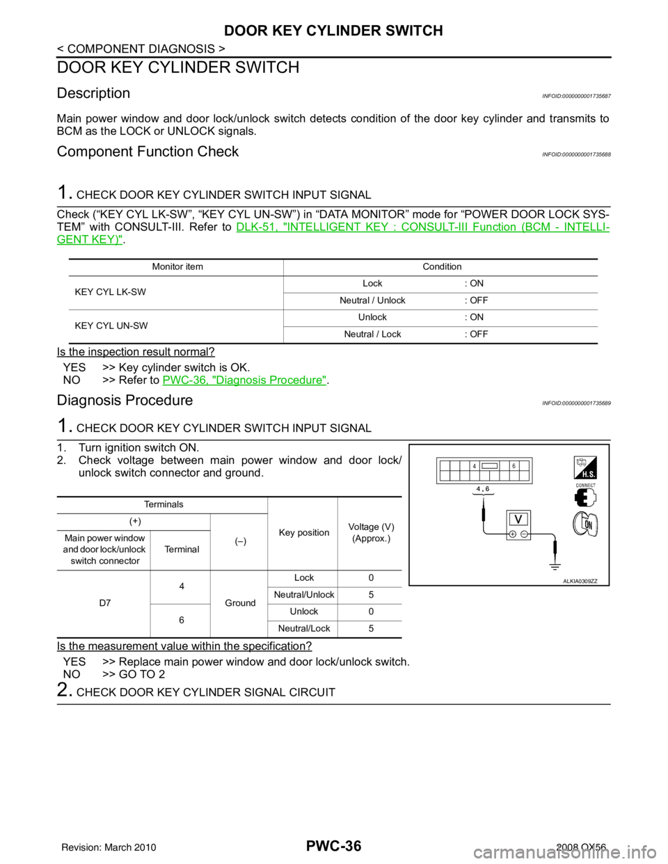
1. CHECK DOOR KEY CYLINDER SWITCH INPUT SIGNAL
1. Turn ignition switch ON.
2. Check voltage between main power window and door lock/ unlock switch connector and ground.
Is the measurement value within the specification?
YES >> Replace main power window and door lock/unlock switch.
NO >> GO TO 2
2. CHECK DOOR KEY CYLINDER SIGNAL CIRCUIT
Monitor item Condition
KEY CYL LK-SW Lock
: ON
Neutral / Unlock : OFF
KEY CYL UN-SW Unlock
: ON
Neutral / Lock : OFF
Te r m i n a l s
Key positionVoltage (V)
(Approx.)
(+)
(–)
Main power window
and door lock/unlock switch connector Te r m i n a l
D7 4
Ground Lock
0
Neutral/Unlock 5
6 Unlock
0
Neutral/Lock 5
ALKIA0309ZZ
Revision: March 2010 2008 QX56
Page 2878 of 4083
DOOR KEY CYLINDER SWITCHPWC-37
< COMPONENT DIAGNOSIS >
C
DE
F
G H
I
J
L
M A
B
PWC
N
O P
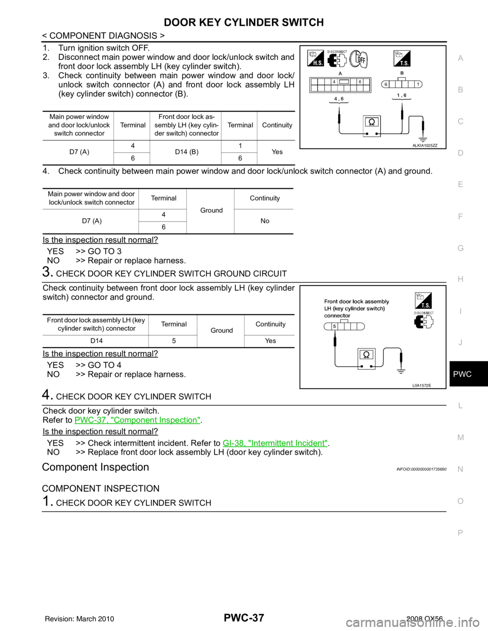
1. Turn ignition switch OFF.
2. Disconnect main power window and door lock/unlock switch and front door lock assembly LH (key cylinder switch).
3. Check continuity between main power window and door lock/ unlock switch connector (A) and front door lock assembly LH
(key cylinder switch) connector (B).
4. Check continuity between main power window and door lock/unlock switch connector (A) and ground.
Is the inspection result normal?
YES >> GO TO 3
NO >> Repair or replace harness.
3. CHECK DOOR KEY CYLINDER SWITCH GROUND CIRCUIT
Check continuity between front door lock assembly LH (key cylinder
switch) connector and ground.
Is the inspection result normal?
YES >> GO TO 4
NO >> Repair or replace harness.
4. CHECK DOOR KEY CYLINDER SWITCH
Check door key cylinder switch.
Refer to PWC-37, "
Component Inspection".
Is the inspection result normal?
YES >> Check intermittent incident. Refer to GI-38, "Intermittent Incident".
NO >> Replace front door lock assembly LH (door key cylinder switch).
Component InspectionINFOID:0000000001735690
COMPONENT INSPECTION
1. CHECK DOOR KEY CYLINDER SWITCH
Main power window
and door lock/unlock switch connector Te r m i n a lFront door lock as-
sembly LH (key cylin-
der switch) connector Terminal Continuity
D7 (A) 4
D14 (B) 1
Ye s
66
Main power window and door lock/unlock switch connector Te r m i n a l
Ground Continuity
D7 (A) 4
No
6
ALKIA1025ZZ
Front door lock assembly LH (key
cylinder switch) connector Te r m i n a l
GroundContinuity
D14 5 Yes
LIIA1572E
Revision: March 2010 2008 QX56
Page 2879 of 4083
PWC-38
< COMPONENT DIAGNOSIS >
DOOR KEY CYLINDER SWITCH
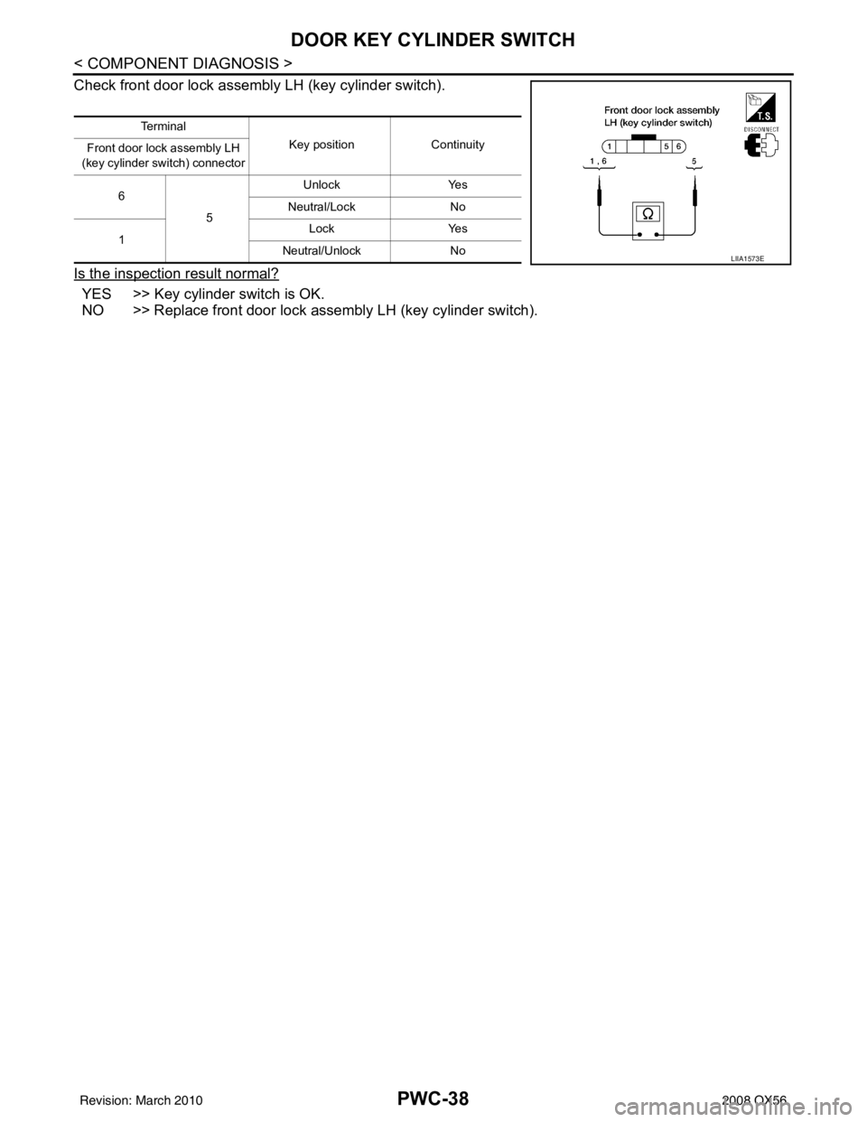
Check front door lock assembly LH (key cylinder switch).
Is the inspection result normal?
YES >> Key cylinder switch is OK.
NO >> Replace front door lock assembly LH (key cylinder switch).
Te r m i n a lKey positionContinuity
Front door lock assembly LH
(key cylinder switch) connector
6 5 Unlock
Yes
Neutral/Lock No
1 Lock
Yes
Neutral/Unlock No
LIIA1573E
Revision: March 2010 2008 QX56
Page 2880 of 4083
POWER WINDOW SERIAL LINKPWC-39
< COMPONENT DIAGNOSIS >
C
DE
F
G H
I
J
L
M A
B
PWC
N
O P
POWER WINDOW SERIAL LINK
POWER WINDOW MAIN SWITCH
POWER WINDOW MAIN SWITCH : DescriptionINFOID:0000000001735691
Main power window and door lock/unlock switch, power window and door lock/unlock switch RH and BCM
transmit and receive the signal by power window serial link.
The signal mentioned below is transmitted from BCM to main power window and door lock/unlock switch and
power window and door lock/unlock switch RH
• Keyless power window down signal
The signal mentioned below is transmitted from main pow er window and door lock/unlock switch to power win-
dow and door lock/unlock switch RH
• Front door window RH operation signal
• Power window control by key cylinder switch signal
• Power window lock switch signal
• Retained power operation signal
POWER WINDOW MAIN SWITCH : Component Function CheckINFOID:0000000001735692
1. CHECK MAIN POWER WINDOW AND DOOR LOCK/UNLOCK SWITCH OUTPUT SIGNAL
Check (“CDL LOCK SW ”, “CDL UNLOCK SW”) in “D ATA MONITOR” mode for “POWER DOOR LOCK SYS-
TEM” with CONSULT-III. Refer to DLK-48, "
DOOR LOCK : CONSULT-III Function (BCM - DOOR LOCK)".
Is the inspection result normal?
YES >> Power window serial link is OK.
NO >> Refer to PWC-39, "
POWER WINDOW MAIN SWITCH : Diagnosis Procedure".
POWER WINDOW MAIN SWITCH : Diagnosis ProcedureINFOID:0000000001735693
Power Window Serial Link Check
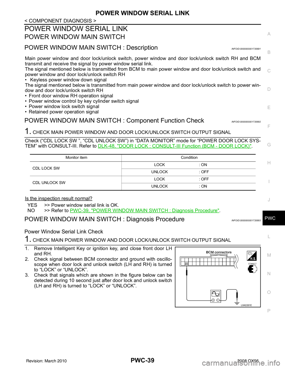
1. CHECK MAIN POWER WINDOW AND DOOR LOCK/UNLOCK SWITCH OUTPUT SIGNAL
1. Remove Intelligent Key or ignition key, and close front door LH and RH.
2. Check signal between BCM connector and ground with oscillo- scope when door lock and unlock switch (LH and RH) is turned
to “LOCK” or “UNLOCK”.
3. Check that signals which are shown in the figure below can be detected during 10 second just after door lock and unlock switch
(LH and RH) is turned to “LOCK” or “UNLOCK”.
Monitor item Condition
CDL LOCK SW LOCK
: ON
UNLOCK : OFF
CDL UNLOCK SW LOCK
: OFF
UNLOCK : ON
LIIA0391E
Revision: March 2010 2008 QX56
Page 2881 of 4083
PWC-40
< COMPONENT DIAGNOSIS >
POWER WINDOW SERIAL LINK
Is the inspection result normal?
YES >> Power window serial link is OK.
NO >> GO TO 2
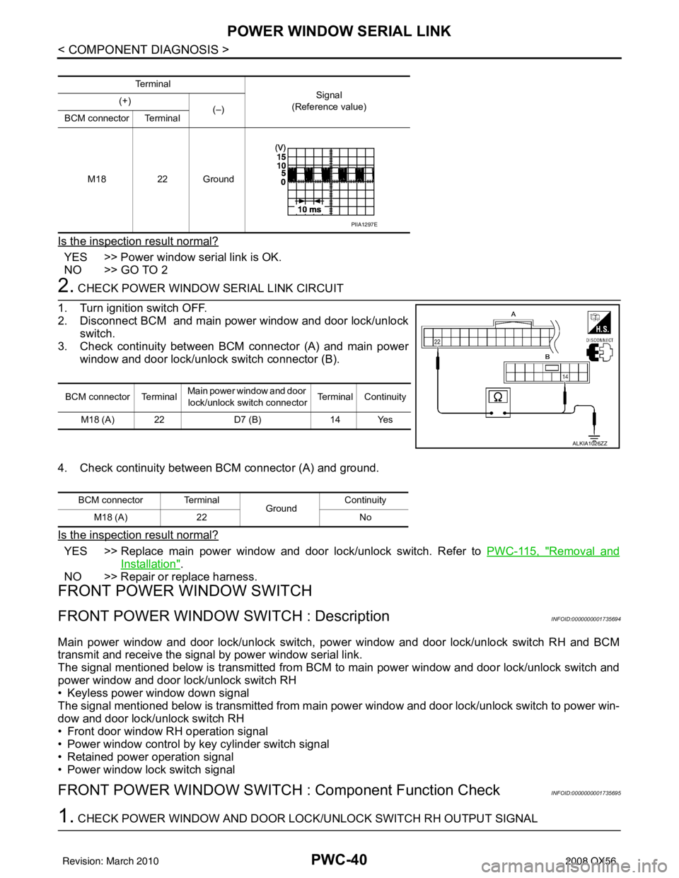
2. CHECK POWER WINDOW SERIAL LINK CIRCUIT
1. Turn ignition switch OFF.
2. Disconnect BCM and main power window and door lock/unlock switch.
3. Check continuity between BCM connector (A) and main power window and door lock/unlock switch connector (B).
4. Check continuity between BCM connector (A) and ground.
Is the inspection result normal?
YES >> Replace main power window and door lock/unlock switch. Refer to PWC-115, "Removal and
Installation".
NO >> Repair or replace harness.
FRONT POWER WINDOW SWITCH
FRONT POWER WINDOW SWITCH : DescriptionINFOID:0000000001735694
Main power window and door lock/unlock switch, power window and door lock/unlock switch RH and BCM
transmit and receive the signal by power window serial link.
The signal mentioned below is transmitted from BCM to main power window and door lock/unlock switch and
power window and door lock/unlock switch RH
• Keyless power window down signal
The signal mentioned below is transmitted from main power window and door lock/unlock switch to power win-
dow and door lock/unlock switch RH
• Front door window RH operation signal
• Power window control by key cylinder switch signal
• Retained power operation signal
• Power window lock switch signal
FRONT POWER WINDOW SWITCH : Component Function CheckINFOID:0000000001735695
1. CHECK POWER WINDOW AND DOOR LOCK/UNLOCK SWITCH RH OUTPUT SIGNAL
Te r m i n a l
Signal
(Reference value)
(+)
(–)
BCM connector Terminal
M18 22 Ground
PIIA1297E
BCM connector Terminal Main power window and door
lock/unlock switch connector Terminal Continuity
M18 (A) 22 D7 (B)14 Yes
ALKIA1026ZZ
BCM connector Terminal
GroundContinuity
M18 (A) 22 No
Revision: March 2010 2008 QX56
Page 2882 of 4083
POWER WINDOW SERIAL LINKPWC-41
< COMPONENT DIAGNOSIS >
C
DE
F
G H
I
J
L
M A
B
PWC
N
O P
Check (“CDL LOCK SW ”, “CDL UNLOCK SW”) in “D ATA MONITOR” mode for “POWER DOOR LOCK SYS-
TEM” with CONSULT-III. Refer to DLK-48, "
DOOR LOCK : CONSULT-III Function (BCM - DOOR LOCK)".
Is the inspection result normal?
YES >> Power window serial link is OK.
NO >> Refer to PWC-41, "
FRONT POWER WINDOW SWITCH : Diagnosis Procedure".
FRONT POWER WINDOW SWIT CH : Diagnosis ProcedureINFOID:0000000001735696
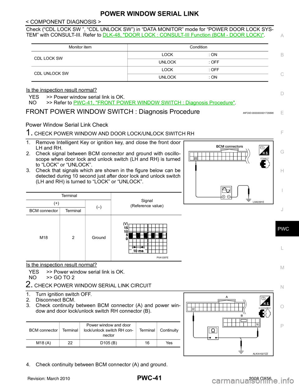
Power Window Serial Link Check
1. CHECK POWER WINDOW AND DOOR LOCK/UNLOCK SWITCH RH
1. Remove Intelligent Key or ignition key, and close the front door LH and RH.
2. Check signal between BCM connector and ground with oscillo- scope when door lock and unlock switch (LH and RH) is turned
to “LOCK” or “UNLOCK”.
3. Check that signals which are shown in the figure below can be detected during 10 second just after door lock and unlock switch
(LH and RH) is turned to “LOCK” or “UNLOCK”.
Is the inspection result normal?
YES >> Power window serial link is OK.
NO >> GO TO 2
2. CHECK POWER WINDOW SERIAL LINK CIRCUIT
1. Turn ignition switch OFF.
2. Disconnect BCM.
3. Check continuity between BCM connector (A) and power win- dow and door lock/unlock switch RH connector (B).
4. Check continuity between BCM connector (A) and ground.
Monitor item Condition
CDL LOCK SW LOCK
: ON
UNLOCK : OFF
CDL UNLOCK SW LOCK
: OFF
UNLOCK : ON
Te r m i n a l
Signal
(Reference value)
(+)
(–)
BCM connector Terminal
M18 2 Ground
LIIA0391E
PIIA1297E
BCM connector Terminal Power window and door
lock/unlock switch RH con-
nector Terminal Continuity
M18 (A) 22 D105 (B)16 Yes
ALKIA1027ZZ
Revision: March 2010 2008 QX56