2008 INFINITI QX56 key
[x] Cancel search: keyPage 2812 of 4083

PG
HARNESSPG-45
< COMPONENT DIAGNOSIS >
C
DE
F
G H
I
J
K L
B A
O P
N
C1 E5 W/24 : To F14
C1 E119 W/16: IPDM E/R (intelligent power distri-
bution module engine room)
C2 E7 GR/2 : Fusible link box (battery) D1 E120 W/6: IPDM E/R (intelligent power distri-
bution module engine room)
C2 E9 — : Body ground E1 E121 BR/12: IPDM E/R (intelligent power distri-
bution module engine room)
D4 E11 B/8 : Front combination lamp LH (without
daytime running lights) C1 E122 W/12: IPDM E/R (intelligent power distri-
bution module engine room)
D4 E11 B/8 : Front combination lamp LH (with
daytime running lights)
C1 E123 BR/8: IPDM E/R (intelligent power distri-
bution module engine room)
D3 E12 B/5 : Stop lamp relay D1 E124 W/6: IPDM E/R (intelligent power distri-
bution module engine room)
D4 E14 — : Body ground F3 E125 B/47: ABS actuator and electric unit
(control unit)
C2 E15 — : Body ground D4 E126 — : Body ground
C1 E16 B/40 : ECM C2 E130 W/2 : Compressor motor relay
E4 E18 GR/2 : Front wheel sensor LH C3 E131 W/2 : Compressor motor relay
D1 E19 W/16 : To F33 C3 E134 GR/6 : ICC brake hold relay
E3 E21 GR/2 : Brake fluid level switch C2 E135 GR/2 : Transfer dropping resister
E2 E23 GR/6 : Front wiper motor C1 E140 BR/6 : Trailer tow relay-2
D4 E24 — : Body ground B2 E153 W/2 : Transfer motor relay
F3 E25 BR/3 : Intelligent key warning buzzer B2 E154 W/2 : Transfer motor relay
C3 E27 BR/2 : Fusible link box (battery) D3 E156 L/4 : Trailer turn relay LH
C2 E30 /1 : Fusible link box (battery )D3 E157 L/4 : Trailer turn relay RH
E3 E31 B/3 : Front pressure sensor D5 E158 B/3 : Front sonar sensor LH outer
E3 E32 B/3 : Rear pressure sensor D5 E159 GR/3 : To E164
E1 E39 W/2 : To F34 B4 E160 GR/3 : To E165
D3 E40 B/3 : To E201 C3 E161 B/3 : Battery current sensor
D3 E41 SMJ : To C1 B4 E162 B/3 : Front sonar sensor LH inner
D3 E42 B/6 : ICC sensor C5 E163 B/3 : Front sonar sensor RH inner
E1 E46 B/5 : Transfer shift high relay D5 E164 GR/3 : To E159
D2 E47 B/5 : Transfer shift lo w relayA4 E165 GR/3 : To E160
C4 E48 B/3 : Refrigerant pressure sensor A3 E166 B/3 : Front sonar sensor RH outer
E3 E49 B/6 : Active booster Engine room sub-harness
D1 E69 L/4 : Transfer shut off relay D3 E201 B/3 : To E40
D5 E101 B/3 : Front turn-fog lamp LH C1 E202 /1 : Fusible link box (battery)
A4 E102 B/3 : Front turn-fog lamp RH C2 E203 — : Engine ground
C3 E103 B/5 : Daytime light relay C3 E204 /1 : Generator
D4 E105 BR/2 : Front and rear washer motor C3 E205 B/3 : Generator
E4 E106 BR/2 : Washer fluid level switch C3 E206 /1 : Generator
B3 E107 B/8 : Front combination lamp LH
C5 E113 W/2 : Cooling fan motor
Revision: March 2010 2008 QX56
Page 2820 of 4083
PG
HARNESSPG-53
< COMPONENT DIAGNOSIS >
C
DE
F
G H
I
J
K L
B A
O P
N
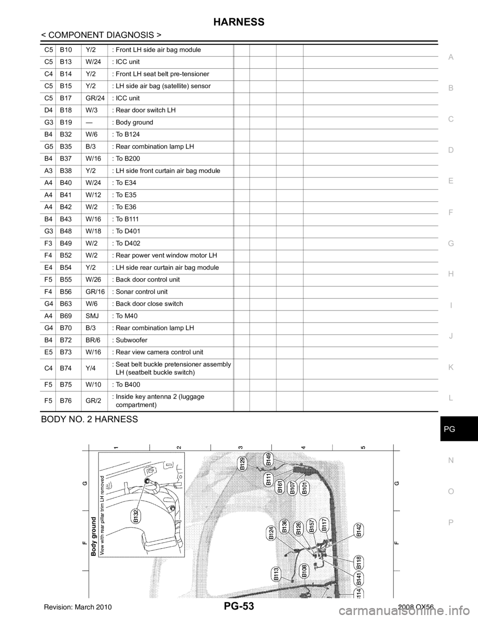
BODY NO. 2 HARNESS
C5 B10 Y/2 : Front LH side air bag module
C5 B13 W/24 : ICC unit
C4 B14 Y/2 : Front LH seat belt pre-tensioner
C5 B15 Y/2 : LH side air bag (satellite) sensor
C5 B17 GR/24 : ICC unit
D4 B18 W/3 : Rear door switch LH
G3 B19 — : Body ground
B4 B32 W/6 : To B124
G5 B35 B/3 : Rear combination lamp LH
B4 B37 W/16 : To B200
A3 B38 Y/2 : LH side front curtain air bag module
A4 B40 W/24 : To E34
A4 B41 W/12 : To E35
A4 B42 W/2 : To E36
B4 B43 W/16 : To B111
G3 B48 W/18 : To D401
F3 B49 W/2 : To D402
F4 B52 W/2 : Rear power vent window motor LH
E4 B54 Y/2 : LH side rear curtain air bag module
F5 B55 W/26 : Back door control unit
F4 B56 GR/16 : Sonar control unit
G4 B63 W/6 : Back door close switch
A4 B69 SMJ : To M40
G4 B70 B/3 : Rear combination lamp LH
B4 B72 BR/6 : Subwoofer
E5 B73 W/16 : Rear view camera control unit
C4 B74 Y/4
: Seat belt buckle pretensioner assembly
LH (seatbelt buckle switch)
F5 B75 W/10 : To B400
F5 B76 GR/2 : Inside key antenna 2 (luggage
compartment)
Revision: March 2010
2008 QX56
Page 2823 of 4083
PG-56
< COMPONENT DIAGNOSIS >
HARNESS
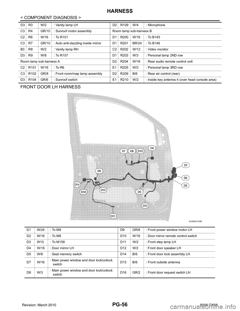
FRONT DOOR LH HARNESS
D3 R3 W/2 : Vanity lamp LHD2 R109 W/4 : Microphone
C3 R4 GR/10 : Sunroof motor assembly Room lamp sub-harness B
C2 R6 W/16 : To R101 D1 R200 W/16 : To B145
C3 R7 GR/10 : Auto anti-dazzling inside mirror D1 R201 BR/24 : To B146
B3 R8 W/2 : Vanity lamp RH C2 R202 W/12 : Video monitor
D3 R9 W/8 : To R107 D1 R203 W/3 : Personal lamp 2ND row
Room lamp sub-harness A D2 R204 W/16 : Rear audio remote control unit
C2 R101 W/16 : To R6 E1 R205 W/3 : Personal lamp 3RD row
C3 R102 GR/8 : Front room/map lamp assembly D2 R209 B/6 : Rear air control (rear)
D3 R104 GR/6 : Sunroof switch E1 R210 W/2 : Inside key antenna 4 (over head console area)
ALMIA0215GB
D1 W/24 : To M9 D9 GR/6 : Front power window motor LH
D2 W/16 : To M8 D10 W/16 : Door mirror remote control switch
D3 W10 : To M158 D11 W/2 : Front step lamp LH
D4 W/16 : Door mirror LH D12 W/2 : Front door speaker LH
D5 W/8 : Seat memory switch D14 B/6 : Front door lock assembly LH
D7 W/16 : Main power window and door lock/unlock
switch D15 B/6 : Front outside antenna
D8 W/3 : Main power window and door lock/unlock
switch
D16 GR/2 : Front door request switch LH
Revision: March 2010
2008 QX56
Page 2843 of 4083

PWC-2
PASSENGER SIDE : Description ...........................25
PASSENGER SIDE : Compo nent Function Check
...
25
PASSENGER SIDE : Diagnosis Procedure ........ ...25
REAR LH ................................................................ ...28
REAR LH : Description ...........................................28
REAR LH : Component Function Check ................28
REAR LH : Diagnosis Procedure ............................28
REAR RH ............................................................... ...30
REAR RH : Description ..........................................31
REAR RH : Component Function Check ................31
REAR RH : Diagnosis Procedure ...........................31
DOOR SWITCH .................................................34
Description ..............................................................34
Component Function Check ...................................34
Diagnosis Procedure ..............................................34
Component Inspection ............................................35
DOOR KEY CYLINDER SWITCH ......................36
Description ........................................................... ...36
Component Function Check ...................................36
Diagnosis Procedure ..............................................36
Component Inspection ............................................37
POWER WINDOW SERIAL LINK .....................39
POWER WINDOW MAIN SWITCH ........................ ...39
POWER WINDOW MAIN SWITCH : Description ...39
POWER WINDOW MAIN SWITCH : Component
Function Check .......................................................
39
POWER WINDOW MAIN SWITCH : Diagnosis
Procedure ...............................................................
39
FRONT POWER WINDOW SWITCH ..................... ...40
FRONT POWER WINDOW SWITCH : Descrip-
tion ..........................................................................
40
FRONT POWER WINDOW SWITCH : Compo-
nent Function Check ...............................................
40
FRONT POWER WINDOW SWITCH : Diagnosis
Procedure ...............................................................
41
REAR POWER WINDOW SWITCH ....................... ...42
REAR POWER WINDOW SWITCH : Power Win-
dow Serial Link Check Rear LH or RH ...................
42
POWER WINDOW LOCK SWITCH ...................43
Description ........................................................... ...43
Component Function Check ...................................43
REAR POWER VENT WINDOW SWITCH
CIRCUIT CHECK ...............................................
44
Description ........................................................... ...44
Diagnosis Procedure ..............................................44
REAR POWER VENT WINDOW MOTOR LH
CIRCUIT CHECK ...............................................
45
Description ........................................................... ...45
Diagnosis Procedure ..............................................45
REAR POWER VENT WINDOW MOTOR RH
CIRCUIT CHECK ...............................................
46
Description ........................................................... ...46
Diagnosis Procedure ...............................................46
REAR POWER VENT WINDOW RELAY
(OPEN) CHECK .................................................
47
Description ........................................................... ...47
Diagnosis Procedure ...............................................47
REAR POWER VENT WINDOW RELAY
(CLOSE) CHECK ...............................................
49
Description ........................................................... ...49
Diagnosis Procedure ...............................................49
ECU DIAGNOSIS .......................................51
BCM (BODY CONTROL MODULE) ............... ...51
Reference Value .................................................. ...51
Terminal Layout ......................................................53
Physical Values .......................................................53
Wiring Diagram .......................................................59
Fail Safe .................................................................62
DTC Inspection Priority Chart ...............................63
DTC Index ..............................................................63
POWER WINDOW MAIN SWITCH ...................65
Reference Value .................................................. ...65
Wiring Diagram .......................................................67
Fail Safe .................................................................78
FRONT POWER WINDOW SWITCH ................80
Reference Value .................................................. ...80
Wiring Diagram .......................................................82
Fail Safe .................................................................93
SYMPTOM DIAGNOSIS ............................95
NONE OF THE POWER WINDOWS CAN BE
OPERATED USING ANY SWITCH ................ ...
95
Diagnosis Procedure ............................................ ...95
DRIVER SIDE POWER WINDOW ALONE
DOES NOT OPERATE ......................................
96
Diagnosis Procedure ............................................ ...96
FRONT PASSENGER SIDE POWER WIN-
DOW ALONE DOES NOT OPERATE ...............
97
Diagnosis Procedure ............................................ ...97
REAR LH SIDE POWER WINDOW ALONE
DOES NOT OPERATE ......................................
98
Diagnosis Procedure ............................................ ...98
REAR RH SIDE POWER WINDOW ALONE
DOES NOT OPERATE ......................................
99
Diagnosis Procedure ............................................ ...99
ANTI-PINCH SYSTEM DOES NOT OPERATE
NORMALLY (DRIVER SIDE) ...........................
100
Diagnosis Procedure ............................................ .100
Revision: March 2010 2008 QX56
Page 2844 of 4083

PWC-3
C
DE
F
G H
I
J
L
M A
B
PWC
N
O P
ANTI-PINCH SYSTEM DOES NOT OPERATE
NORMALLY (PASSENGER SIDE) ................ ..
101
Diagnosis Procedure ........................................... ..101
ANTI-PINCH SYSTEM DOES NOT OPERATE
NORMALLY (REAR LH SIDE) .........................
102
Diagnosis Procedure ........................................... ..102
ANTI-PINCH SYSTEM DOES NOT OPERATE
NORMALLY (REAR RH SIDE) ........................
103
Diagnosis Procedure ........................................... ..103
AUTO OPERATION DOES NOT OPERATE
BUT MANUAL OPERATES NORMALLY
(DRIVER SIDE) .................................................
104
Diagnosis Procedure .............................................104
AUTO OPERATION DOES NOT OPERATE
BUT MANUAL OPERATES NORMALLY
(PASSENGER SIDE) ...................................... ..
105
Diagnosis Procedure ........................................... ..105
AUTO OPERATION DOES NOT OPERATE
BUT MANUAL OPERATES NORMALLY
(REAR LH SIDE) ..............................................
106
Diagnosis Procedure ........................................... ..106
AUTO OPERATION DOES NOT OPERATE
BUT MANUAL OPERATES NORMALLY
(REAR RH SIDE) ..............................................
107
Diagnosis Procedure ........................................... ..107
POWER WINDOW RETAINED POWER OP-
ERATION DOES NOT OPERATE PROPERLY
..
108
Diagnosis Procedure ........................................... ..108
DOES NOT OPERATE BY KEY CYLINDER
SWITCH ...........................................................
109
Diagnosis Procedure ........................................... ..109
KEYLESS POWER WINDOW DOWN DOES
NOT OPERATE ...............................................
110
Diagnosis Procedure .............................................110
POWER WINDOW LOCK SWITCH DOES
NOT FUNCTION ..............................................
111
Diagnosis Procedure .............................................111
REAR POWER VENT WINDOWS DO NOT
OPERATE .......................................................
112
Diagnosis Procedure .............................................112
PRECAUTION ............................................113
PRECAUTIONS ...............................................113
Precaution for Supplemental Restraint System
(SRS) "AIR BAG" and "SEAT BELT PRE-TEN-
SIONER" ............................................................. ..
113
Precaution Necessary for Steering Wheel Rota-
tion After Battery Disconnect .................................
113
ON-VEHICLE REPAIR ...............................115
POWER WINDOW MAIN SWITCH .................115
Removal and Installation ..................................... ..115
FRONT POWER WINDOW SWITCH ..............116
Removal and Installation .......................................116
REAR POWER WINDOW SWITCH ................117
Removal and Installation .......................................117
REAR POWER VENT WINDOW SWITCH .....118
Removal and Installation .......................................118
Revision: March 2010 2008 QX56
Page 2846 of 4083
POWER WINDOW SYSTEMPWC-5
< FUNCTION DIAGNOSIS >
C
DE
F
G H
I
J
L
M A
B
PWC
N
O P
FUNCTION DIAGNOSIS
POWER WINDOW SYSTEM
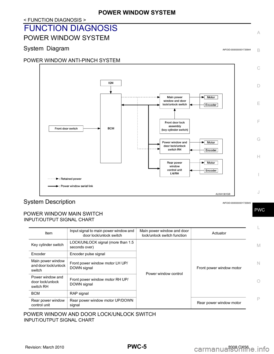
System DiagramINFOID:0000000001735644
POWER WINDOW ANTI-PINCH SYSTEM
System DescriptionINFOID:0000000001735645
POWER WINDOW MAIN SWITCH
INPUT/OUTPUT SIGNAL CHART
POWER WINDOW AND DOOR LOCK/UNLOCK SWITCH
INPUT/OUTPUT SIGNAL CHART
ALKIA1301GB
Item Input signal to main power window and
door lock/unlock switch Main power window and door
lock/unlock switch function Actuator
Key cylinder switch LOCK/UNLOCK signal (more than 1.5
seconds over)
Power window controlFront power window motor
Encoder
Encoder pulse signal
Main power window
and door lock/unlock
switch Front power window motor LH UP/
DOWN signal
Power window and
door lock/unlock
switch RH Front power window motor RH UP/
DOWN signal
BCM RAP signal
Rear power window
control unit Rear power window motor UP/DOWN
signal
Rear power window motor
Revision: March 2010
2008 QX56
Page 2848 of 4083
POWER WINDOW SYSTEMPWC-7
< FUNCTION DIAGNOSIS >
C
DE
F
G H
I
J
L
M A
B
PWC
N
O P
ANTI-PINCH OPERATION
• Pinch foreign material in the door glass during AUTO-U P operation, and it is the anti-pinch function that low-
ers the door glass 150 mm (5.91 in) or 2 seconds when detected.
• Encoder continues detecting the movement of power window motor and transmits to power window switch
as the encoder pulse signal while power window motor is operating.
• Resistance is applied to the power window motor rotation that changes the frequency of encoder pulse sig-
nal if foreign material is trapped in the door glass.
• Front power window switch LH/RH and rear power window control unit LH/RH controls to lower the window glass for 150 mm (5.91 in) or 2 seconds after it detects encoder pulse signal frequency change.
OPERATION CONDITION
• When all door glass AUTO-UP operation is performed ( anti-pinch function does not operate just before the
door glass closes and is fully closed)
NOTE:
Depending on environment and driving conditions, if a similar impact or load is applied to the door glass, it
may lower.
KEY CYLINDER SWITCH OPERATION
Hold the door key cylinder to the LOCK or UNLOCK dire ction for more than 1 second to OPEN or CLOSE front
power windows when ignition switch is OFF. In addition, it stops when key position is moved to NEUTRAL
when operating.
OPERATION CONDITION
• Ignition switch OFF
• Hold door key cylinder to LOCK position for more than 1 second to perform CLOSE operation of the door glass.
• Hold door key cylinder to UNLOCK position for more than 1 second to perform OPEN operation of the door glass.
KEYLESS POWER WINDOW DOWN OPERATION
Front power windows open when the unlock button on Intelligent Key is activated and kept pressed for more
than 3
(NOTE) seconds with the ignition switch OFF. The windows keep opening if the unlock button is continu-
ously pressed.
The power window opening stops when the following operations are performed:
• When the unlock button is kept pressed more than 15 seconds.
• When the ignition switch is turned ON while the power window opening is operated.
• When the unlock button is released.
While retained power operation is activated, ke yless power window down function cannot be operated.
NOTE:
Keyless power window down operation mode can be changed by “PW DOWN SET” mode in “WORK SUP-
PORT”. Refer to SEC-22, "
CONSULT-III Function (INTELLIGENT KEY)".
NOTE:
Use CONSULT-III to change settings.
MODE1 (3sec)/MODE2 (OFF)/MODE3 (5sec)
Revision: March 2010 2008 QX56
Page 2849 of 4083
PWC-8
< FUNCTION DIAGNOSIS >
POWER WINDOW SYSTEM
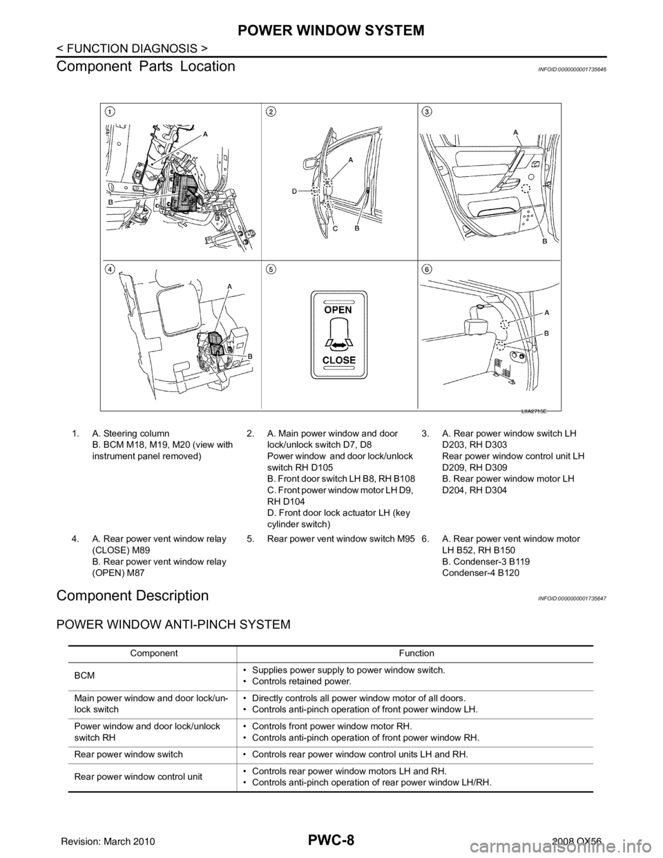
Component Parts Location
INFOID:0000000001735646
Component DescriptionINFOID:0000000001735647
POWER WINDOW ANTI-PINCH SYSTEM
LIIA2715E
1. A. Steering column B. BCM M18, M19, M20 (view with
instrument panel removed) 2. A. Main power window and door
lock/unlock switch D7, D8
Power window and door lock/unlock
switch RH D105
B. Front door switch LH B8, RH B108
C. Front power win dow motor LH D9,
RH D104
D. Front door lock actuator LH (key
cylinder switch) 3. A. Rear power window switch LH
D203, RH D303
Rear power window control unit LH
D209, RH D309
B. Rear power window motor LH
D204, RH D304
4. A. Rear power vent window relay (CLOSE) M89
B. Rear power vent window relay
(OPEN) M87 5. Rear power vent window switch M95 6. A. Rear power vent window motor
LH B52, RH B150
B. Condenser-3 B119
Condenser-4 B120
Component Function
BCM • Supplies power supply to power window switch.
• Controls retained power.
Main power window and door lock/un-
lock switch • Directly controls all power window motor of all doors.
• Controls anti-pinch operation of front power window LH.
Power window and door lock/unlock
switch RH • Controls front power window motor RH.
• Controls anti-pinch operation of front power window RH.
Rear power window switch • Controls rear power window control units LH and RH.
Rear power window control unit • Controls rear power window motors LH and RH.
• Controls anti-pinch operation of rear power window LH/RH.
Revision: March 2010
2008 QX56