Page 2907 of 4083
PWC-66
< ECU DIAGNOSIS >
POWER WINDOW MAIN SWITCH
13
(G/Y) 2 Encoder pulse signal 1 Input When power window mo-
tor operates.
14
(LG/W) Ground Power window serial link Input/
Output IGN SW ON or power win-
dow timer operating.
15
(BR) Ground Encoder power supply Output When ignition switch ON or
power window timer oper-
ates.10
17
(B) Ground Ground
—— 0
19
(W/R) Ground Battery power supply
Input— Battery voltage
Te r m i n a l N o .
(Wire color) Description
ConditionVoltage [V]
(Approx.)
+ – Signal name Input/
Output
JMKIA0070GB
JPMIA0013GB
Revision: March 2010 2008 QX56
Page 2921 of 4083
PWC-80
< ECU DIAGNOSIS >
FRONT POWER WINDOW SWITCH
FRONT POWER WINDOW SWITCH
Reference Value INFOID:0000000001735740
TERMINAL LAYOUT
PHYSICAL VALUES
POWER WINDOW AND DOOR LOCK/UNLOCK SWITCH RH
LIIA2454E
Te r m i n a l N o .(Wire color) Description
ConditionVoltage [V]
(Approx.)
+ – Signal nameInput/
Output
3
(W/B) Ground Encoder ground
—— 0
4
(G/R) Ground Encoder power supply Output When ignition switch ON or
power window timer operates
10
8
(L) 9
Power window motor
UP signal Output
When power window motor is
UP at operated. Battery voltage
9
(G) 8Power window motor
DOWN signal OutputWhen power window motor is
DOWN at operated. Battery voltage
10
(W/R) Ground Battery power supply Input
—Battery voltage
11
(B) Ground Ground
—— 0
12
(G/Y) 3 Encoder pulse signal 1 Input When power window motor op-
erates.
JMKIA0070GB
Revision: March 2010
2008 QX56
Page 2989 of 4083
INSPECTION AND ADJUSTMENTRF-5
< BASIC INSPECTION >
C
DE
F
G H
I
J
L
M A
B
RF
N
O P
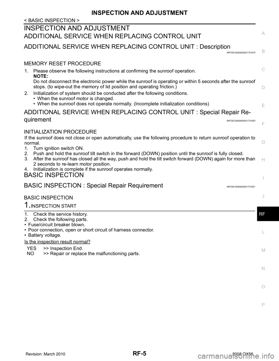
INSPECTION AND ADJUSTMENT
ADDITIONAL SERVICE WHEN REPLACING CONTROL UNIT
ADDITIONAL SERVICE WHEN REPL ACING CONTROL UNIT : Description
INFOID:0000000001731919
MEMORY RESET PROCEDURE
1. Please observe the following instructi ons at confirming the sunroof operation.
NOTE:
Do not disconnect the electronic power while the sunroof is operating or within 5 seconds after the sunroof
stops. (to wipe-out the memory of lid position and operating friction.)
2. Initialization of system should be conducted after the following conditions.
• When the sunroof motor is changed.
• When the sunroof does not operate normally. (Incomplete initialization conditions)
ADDITIONAL SERVICE WHEN REPLACING CONTROL UNIT : Special Repair Re-
quirement
INFOID:0000000001731920
INITIALIZATION PROCEDURE
If the sunroof does not close or open automatically, us e the following procedure to return sunroof operation to
normal.
1. Turn ignition switch ON.
2. Push and hold the sunroof tilt switch in the forw ard (DOWN) position until the sunroof is fully closed.
3. After the sunroof has closed all the way, push and hold the tilt switch forward (DOWN) again for more than 2 seconds to re-learn motor position.
4. Initialization is complete if the sunroof operates normally.
BASIC INSPECTION
BASIC INSPECTION : Special Repair RequirementINFOID:0000000001731921
BASIC INSPECTION
1.INSPECTION START
1. Check the service history.
2. Check the following parts.
• Fuse/circuit breaker blown.
• Poor connection, open or short circuit of harness connector.
• Battery voltage.
Is the inspection result normal?
YES >> Inspection End.
NO >> Repair or replace the malfunctioning parts.
Revision: March 2010 2008 QX56
Page 2994 of 4083
RF-10
< COMPONENT DIAGNOSIS >
POWER SUPPLY AND GROUND CIRCUIT
COMPONENT DIAGNOSIS
POWER SUPPLY AND GROUND CIRCUIT
SUNROOF MOTOR ASSEMBLY
SUNROOF MOTOR ASSEMBLY : Diagnosis ProcedureINFOID:0000000001731928
SUNROOF MOTOR ASSEMBLY
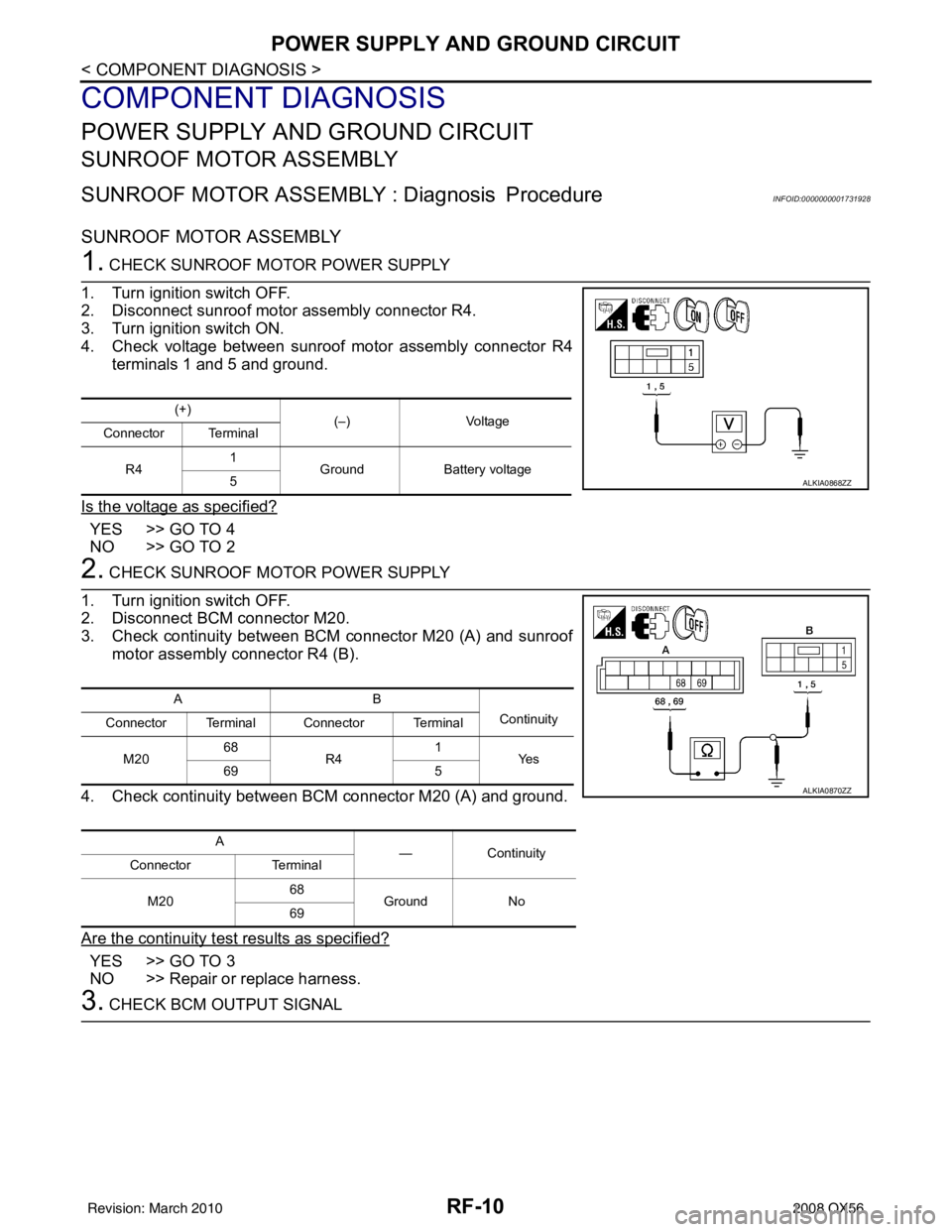
1. CHECK SUNROOF MOTOR POWER SUPPLY
1. Turn ignition switch OFF.
2. Disconnect sunroof motor assembly connector R4.
3. Turn ignition switch ON.
4. Check voltage between sunroof motor assembly connector R4 terminals 1 and 5 and ground.
Is the voltage as specified?
YES >> GO TO 4
NO >> GO TO 2
2. CHECK SUNROOF MOTOR POWER SUPPLY
1. Turn ignition switch OFF.
2. Disconnect BCM connector M20.
3. Check continuity between BCM connector M20 (A) and sunroof motor assembly connector R4 (B).
4. Check continuity between BCM connector M20 (A) and ground.
Are the continuity test results as specified?
YES >> GO TO 3
NO >> Repair or replace harness.
3. CHECK BCM OUTPUT SIGNAL
(+) (–)Voltage
Connector Terminal
R4 1
Ground Battery voltage
5
ALKIA0868ZZ
AB
Continuity
Connector Terminal Connector Terminal
M20 68
R4 1
Ye s
69 5
A —Contin u it y
Connector Terminal
M20 68
Ground No
69
ALKIA0870ZZ
Revision: March 2010 2008 QX56
Page 2995 of 4083
POWER SUPPLY AND GROUND CIRCUITRF-11
< COMPONENT DIAGNOSIS >
C
DE
F
G H
I
J
L
M A
B
RF
N
O P
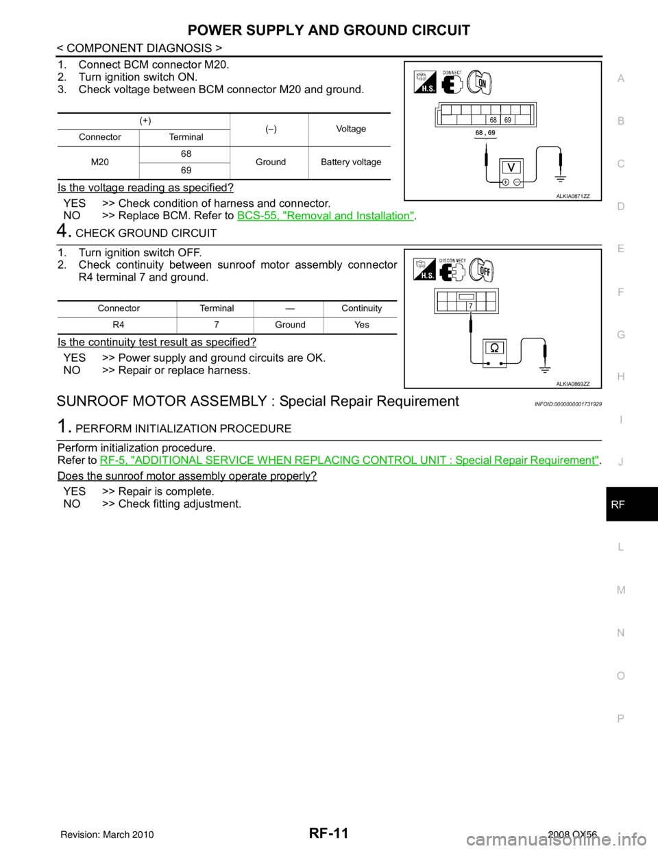
1. Connect BCM connector M20.
2. Turn ignition switch ON.
3. Check voltage between BCM connector M20 and ground.
Is the voltage reading as specified?
YES >> Check condition of harness and connector.
NO >> Replace BCM. Refer to BCS-55, "
Removal and Installation".
4. CHECK GROUND CIRCUIT
1. Turn ignition switch OFF.
2. Check continuity between sunroof motor assembly connector R4 terminal 7 and ground.
Is the continuity test result as specified?
YES >> Power supply and ground circuits are OK.
NO >> Repair or replace harness.
SUNROOF MOTOR ASSEMBLY : Special Repair RequirementINFOID:0000000001731929
1. PERFORM INITIALIZATION PROCEDURE
Perform initialization procedure.
Refer to RF-5, "
ADDITIONAL SERVICE WHEN REPLACING CO NTROL UNIT : Special Repair Requirement".
Does the sunroof motor assembly operate properly?
YES >> Repair is complete.
NO >> Check fitting adjustment.
(+) (–) Voltage
Connector Terminal
M20 68
Ground Battery voltage
69
ALKIA0871ZZ
Connector Terminal—Continuity
R4 7Ground Yes
ALKIA0869ZZ
Revision: March 2010 2008 QX56
Page 2996 of 4083
RF-12
< COMPONENT DIAGNOSIS >
SUNROOF SWITCH CIRCUIT
SUNROOF SWITCH CIRCUIT
DescriptionINFOID:0000000001731930
The BCM supplies power to the integrated CPU of the sunroof motor assembly. The tilt and slide functions of
the sunroof motor assembly is controlled by the sunroof switch.
Component Function CheckINFOID:0000000001731931
1. CHECK SUNROOF MOTOR FUNCTION
Do tilt up/down & slide open/close functi ons operate normally with sunroof switch?
Is the inspection result normal?
YES >> Sunroof motor assembly is OK.
NO >> Refer to RF-10, "
SUNROOF MOTOR ASSEMBLY : DiagnosisProcedure".
Diagnosis ProcedureINFOID:0000000001731932
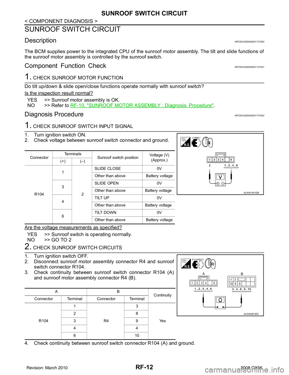
1. CHECK SUNROOF SWITCH INPUT SIGNAL
1. Turn ignition switch ON.
2. Check voltage between sunroof switch connector and ground.
Are the voltage measurements as specified?
YES >> Sunroof switch is operating normally.
NO >> GO TO 2
2. CHECK SUNROOF SWITCH CIRCUITS
1. Turn ignition switch OFF.
2. Disconnect sunroof motor assembly connector R4 and sunroof switch connector R104.
3. Check continuity between sunroof switch connector R104 (A) and sunroof motor assembly connector R4 (B).
4. Check continuity between sunroof switch connector R104 (A) and ground.
Connector Te r m i n a l s
Sunroof switch position Voltage (V)
(Approx.)
(+) (–)
R104 1
2SLIDE CLOSE
0V
Other than above Battery voltage
3 SLIDE OPEN
0V
Other than above Battery voltage
4 TILT UP
0V
Other than above Battery voltage
6 TILT DOWN
0V
Other than above Battery voltage
ALKIA1041GB
AB
Continuity
Connector Terminal Connector Terminal
R104 1
R4 3
Ye s
28
39
44
61
0
ALKIA0873ZZ
Revision: March 2010 2008 QX56
Page 2998 of 4083
RF-14
< COMPONENT DIAGNOSIS >
DOOR SWITCH
DOOR SWITCH
DescriptionINFOID:0000000006081160
Detects door open/close condition and transmits the signal to BCM.
Component Function CheckINFOID:0000000006081161
1. CHECK FRONT DOOR SWITCH INPUT SIGNAL
Check (“DOOR SW-DR” and “DOOR SW-AS”) in “DATA MONITOR” mode with CONSULT-III. Refer to PWC-
10, "RETAINED PWR : CONSULT-III Function (BCM - RETAINED PWR)".
Is the inspection result normal?
YES >> Front door switch circuit is OK.
NO >> Refer to RF-14, "
Diagnosis Procedure".
Diagnosis ProcedureINFOID:0000000006081162
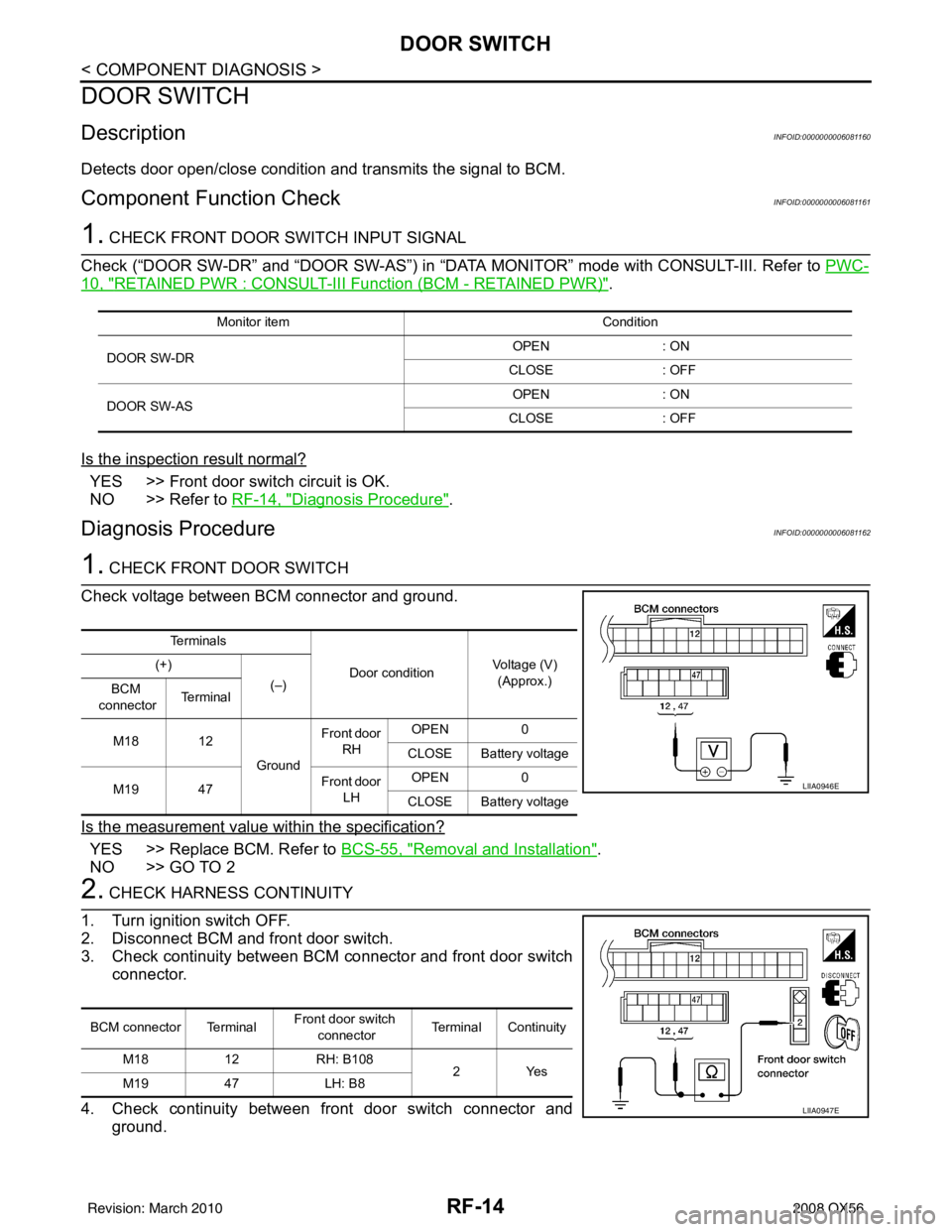
1. CHECK FRONT DOOR SWITCH
Check voltage between BCM connector and ground.
Is the measurement value within the specification?
YES >> Replace BCM. Refer to BCS-55, "Removal and Installation".
NO >> GO TO 2
2. CHECK HARNESS CONTINUITY
1. Turn ignition switch OFF.
2. Disconnect BCM and front door switch.
3. Check continuity between BCM connector and front door switch connector.
4. Check continuity between front door switch connector and ground.
Monitor item Condition
DOOR SW-DR OPEN
: ON
CLOSE : OFF
DOOR SW-AS OPEN
: ON
CLOSE : OFF
Te r m i n a l s
Door conditionVoltage (V)
(Approx.)
(+)
(–)
BCM
connector Te r m i n a l
M18 12 GroundFront door
RH OPEN
0
CLOSE Battery voltage
M19 47 Front door
LH OPEN
0
CLOSE Battery voltage
LIIA0946E
BCM connector Terminal Front door switch
connector Terminal Continuity
M18 12RH: B108
2Yes
M19 47LH: B8
LIIA0947E
Revision: March 2010 2008 QX56
Page 2999 of 4083
DOOR SWITCHRF-15
< COMPONENT DIAGNOSIS >
C
DE
F
G H
I
J
L
M A
B
RF
N
O P
Is the inspection result normal?
YES >> GO TO 3
NO >> Repair or replace harness.
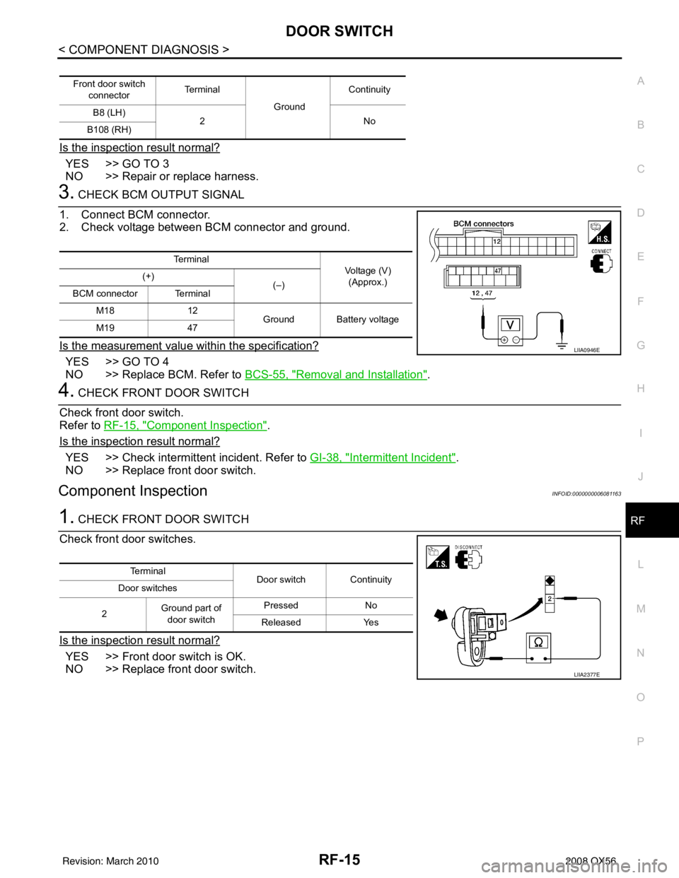
3. CHECK BCM OUTPUT SIGNAL
1. Connect BCM connector.
2. Check voltage between BCM connector and ground.
Is the measurement value within the specification?
YES >> GO TO 4
NO >> Replace BCM. Refer to BCS-55, "
Removal and Installation".
4. CHECK FRONT DOOR SWITCH
Check front door switch.
Refer to RF-15, "
Component Inspection".
Is the inspection result normal?
YES >> Check intermittent incident. Refer to GI-38, "Intermittent Incident".
NO >> Replace front door switch.
Component InspectionINFOID:0000000006081163
1. CHECK FRONT DOOR SWITCH
Check front door switches.
Is the inspection result normal?
YES >> Front door switch is OK.
NO >> Replace front door switch.
Front door switch connector Te r m i n a l
GroundContinuity
B8 (LH) 2N o
B108 (RH)
Te r m i n a l
Voltage (V)
(Approx.)
(+)
(–)
BCM connector Terminal
M18 12
Ground Battery voltage
M19 47
LIIA0946E
Te r m i n a l
Door switch Continuity
Door switches
2 Ground part of
door switch Pressed
No
Released Yes
LIIA2377E
Revision: March 2010 2008 QX56