2008 INFINITI QX56 low oil pressure
[x] Cancel search: low oil pressurePage 1836 of 4083
OIL PAN AND OIL STRAINEREM-33
< ON-VEHICLE REPAIR >
C
DE
F
G H
I
J
K L
M A
EM
NP
O
OIL PAN AND OIL STRAINER
Removal and InstallationINFOID:0000000001538816
REMOVAL
WARNING:
To avoid the danger of being scalded, never drain the engine oil when the engine is hot.
1. Remove the engine. Refer to
EM-78, "
Removal and Installation".
2. Remove the oil pan (lower) using the following steps.
a. Remove the oil pan (lower) bolts using power tool.
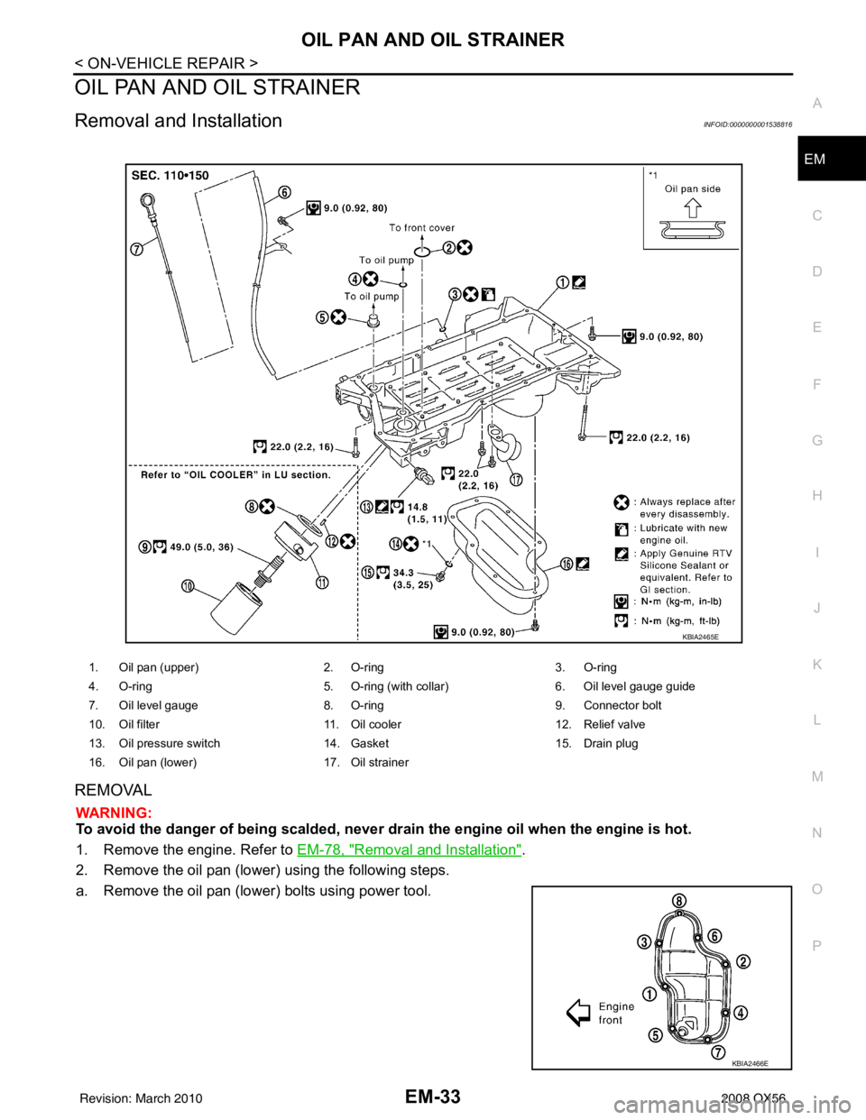
1. Oil pan (upper) 2. O-ring3. O-ring
4. O-ring 5. O-ring (with collar)6. Oil level gauge guide
7. Oil level gauge 8. O-ring9. Connector bolt
10. Oil filter 11. Oil cooler12. Relief valve
13. Oil pressure switch 14. Gasket15. Drain plug
16. Oil pan (lower) 17. Oil strainer
KBIA2465E
KBIA2466E
Revision: March 2010 2008 QX56
Page 1844 of 4083
FUEL INJECTOR AND FUEL TUBEEM-41
< ON-VEHICLE REPAIR >
C
DE
F
G H
I
J
K L
M A
EM
NP
O
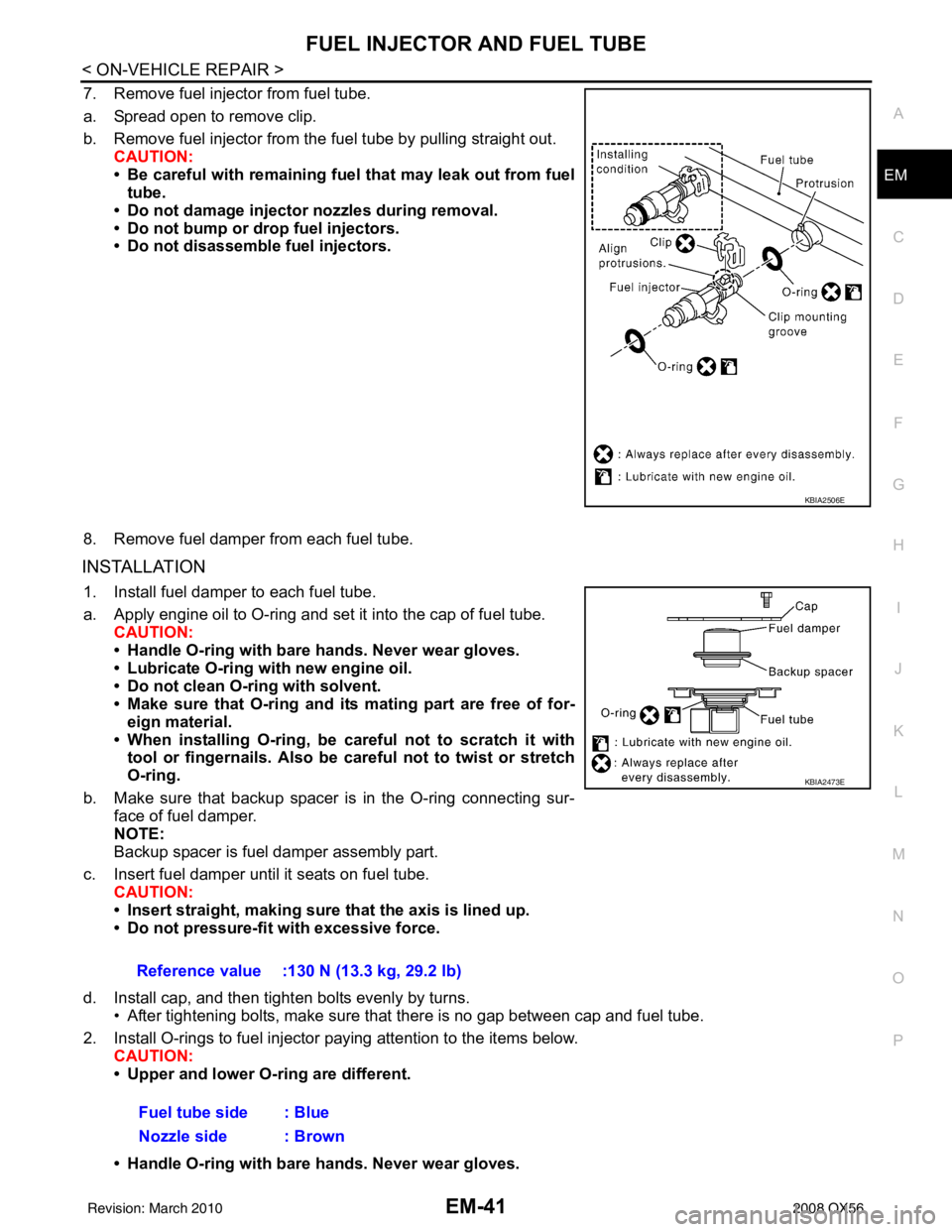
7. Remove fuel injector from fuel tube.
a. Spread open to remove clip.
b. Remove fuel injector from the
fuel tube by pulling straight out.
CAUTION:
• Be careful with remaining fuel that may leak out from fuel
tube.
• Do not damage injector nozzles during removal.
• Do not bump or drop fuel injectors.
• Do not disassemble fuel injectors.
8. Remove fuel damper from each fuel tube.
INSTALLATION
1. Install fuel damper to each fuel tube.
a. Apply engine oil to O-ring and set it into the cap of fuel tube. CAUTION:
• Handle O-ring with bare hands. Never wear gloves.
• Lubricate O-ring with new engine oil.
• Do not clean O-ring with solvent.
• Make sure that O-ring and its mating part are free of for- eign material.
• When installing O-ring, be car eful not to scratch it with
tool or fingernails. Also be careful not to twist or stretch
O-ring.
b. Make sure that backup spacer is in the O-ring connecting sur- face of fuel damper.
NOTE:
Backup spacer is fuel damper assembly part.
c. Insert fuel damper until it seats on fuel tube. CAUTION:
• Insert straight, making sure that the axis is lined up.
• Do not pressure-fit with excessive force.
d. Install cap, and then tighten bolts evenly by turns. • After tightening bolts, make sure that there is no gap between cap and fuel tube.
2. Install O-rings to fuel injector paying attention to the items below. CAUTION:
• Upper and lower O-ring are different.
• Handle O-ring with bare hands. Never wear gloves.
KBIA2506E
Reference value :130 N (13.3 kg, 29.2 lb)
Fuel tube side : Blue
Nozzle side : Brown
KBIA2473E
Revision: March 2010 2008 QX56
Page 1845 of 4083
EM-42
< ON-VEHICLE REPAIR >
FUEL INJECTOR AND FUEL TUBE
• Lubricate O-ring with new engine oil.
• Do not clean O-ring with solvent.
• Make sure that O-ring and its mating part are free of foreign material.
• When installing O-ring, be careful not to scratch it with tool or fingernails. Also be careful not to
twist or stretch O-ring. If O-ring was stretc hed while it was being attached, do not insert it
quickly into fuel tube.
• Insert O-ring straight into fuel tube. Do not angle or twist it.
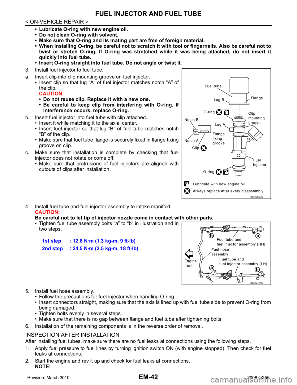
3. Install fuel injector to fuel tube.
a. Insert clip into clip mounting groove on fuel injector. • Insert clip so that lug “A” of fuel injector matches notch “A” ofthe clip.
CAUTION:
• Do not reuse clip. Replace it with a new one.
• Be careful to keep clip from interfering with O-ring. Ifinterference occurs, replace O-ring.
b. Insert fuel injector into fuel tube with clip attached. • Insert it while matching it to the axial center.
• Insert fuel injector so that lug “B” of fuel tube matches notch
“B” of the clip.
• Make sure that fuel tube flange is securely fixed in flange fixing groove on clip.
c. Make sure that installation is complete by checking that fuel injector does not rotate or come off.
• Make sure that protrusions of fuel injectors are aligned withcutouts of clips after installation.
4. Install fuel tube and fuel injector assembly to intake manifold. CAUTION:
Be careful not to let tip of injector nozzle come in contact with other parts.
• Tighten fuel tube assembly bolts “a” to “b” in illustration and in
two steps.
5. Install fuel hose assembly. • Follow the precautions for fuel injector when handling O-ring.
• Insert connectors straight, making sure that the axis is lined up with fuel tube side to prevent O-ring from
being damaged.
• Tighten bolts evenly in several steps.
• Make sure that there is no gap between flange and fuel tube after tightening bolts.
6. Installation of the remaining components is in the reverse order of removal.
INSPECTION AFTER INSTALLATION
After installing fuel tubes, make sure there are no fuel leaks at connections using the following steps.
1. Apply fuel pressure to fuel lines by turning ignition switch ON (with engine stopped). Then check for fuel leaks at connections.
2. Start the engine and rev it up and check for fuel leaks at connections. NOTE:
KBIA2507E
1st step : 12.8 N·m (1.3 kg-m, 9 ft-lb)
2nd step : 24.5 N·m (2.5 kg-m, 18 ft-lb)
KBIA2474E
Revision: March 2010 2008 QX56
Page 1855 of 4083
EM-52
< ON-VEHICLE REPAIR >
TIMING CHAIN
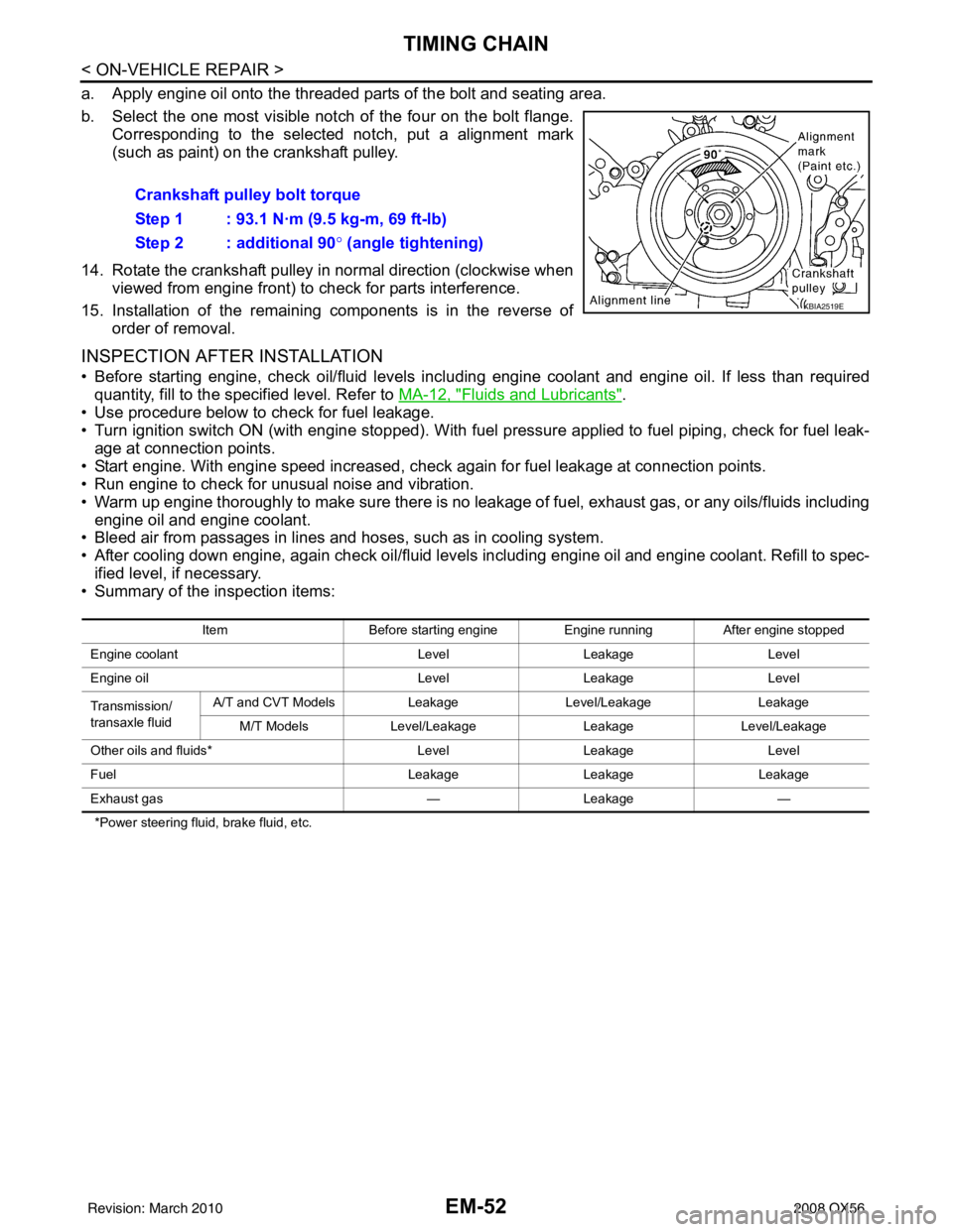
a. Apply engine oil onto the threaded parts of the bolt and seating area.
b. Select the one most visible notch of the four on the bolt flange.Corresponding to the selected notch, put a alignment mark
(such as paint) on the crankshaft pulley.
14. Rotate the crankshaft pulley in normal direction (clockwise when viewed from engine front) to check for parts interference.
15. Installation of the remaining components is in the reverse of order of removal.
INSPECTION AFTER INSTALLATION
• Before starting engine, check oil/fluid levels incl uding engine coolant and engine oil. If less than required
quantity, fill to the specified level. Refer to MA-12, "
Fluids and Lubricants".
• Use procedure below to check for fuel leakage.
• Turn ignition switch ON (with engine stopped). With fuel pressure applied to fuel piping, check for fuel leak- age at connection points.
• Start engine. With engine speed increased, che ck again for fuel leakage at connection points.
• Run engine to check for unusual noise and vibration.
• Warm up engine thoroughly to make sure there is no leakage of fuel, exhaust gas, or any oils/fluids including
engine oil and engine coolant.
• Bleed air from passages in lines and hoses, such as in cooling system.
• After cooling down engine, again check oil/fluid levels including engine oil and engine coolant. Refill to spec-
ified level, if necessary.
• Summary of the inspection items:
*Power steering fluid, brake fluid, etc.
Crankshaft pulley bolt torque
Step 1 : 93.1 N·m (9.5 kg-m, 69 ft-lb)
Step 2 : additional 90 ° (angle tightening)
KBIA2519E
Item Before starting engine Engine runningAfter engine stopped
Engine coolant LevelLeakage Level
Engine oil LevelLeakage Level
Transmission/
transaxle fluid A/T and CVT Models
LeakageLevel/Leakage Leakage
M/T Models Level/Leakage LeakageLevel/Leakage
Other oils and fluids* LevelLeakage Level
Fuel LeakageLeakage Leakage
Exhaust gas —Leakage —
Revision: March 2010 2008 QX56
Page 1866 of 4083
CAMSHAFTEM-63
< ON-VEHICLE REPAIR >
C
DE
F
G H
I
J
K L
M A
EM
NP
O
1. Check engine oil level. Refer to
LU-8, "Inspection".
2. Perform the following procedure so as to prevent the engine from being unintentionally started while checking.
a. Release fuel pressure. Refer to EC-494, "
Fuel Pressure Check".
b. Disconnect ignition coil and injector harness connectors if practical.
3. Remove IVT control solenoid valve.
4. Crank engine, and then make sure that engine oil comes out from IVT control cover oil hole. End cranking after checking.
WARNING:
Be careful not to touch rotating parts (drive be lts, idler pulley, and crankshaft pulley, etc.).
CAUTION:
• Engine oil may squirt from IVT control solenoid valve installation hole during cranking. Use a
shop cloth to prevent engine oil from splash ing on worker, engine components and vehicle.
• Do not allow engine oil to get on rubber components such as drive belts or engine mount insula- tors. Immediately wipe off any splashed engine oil.
5. Clean oil groove between oil strainer and IVT control solenoid valve if engine oil does not come out from IVT control valve cover oil hole. Refer to LU-7, "
Schematic".
6. Remove components between IVT control solenoid valve and camshaft sprocket (INT), and then check each oil groove for clogging.
• Clean oil groove if necessary.
7. After inspection, installation of the remaining components is in the reverse order of removal.
Revision: March 2010 2008 QX56
Page 1872 of 4083
CYLINDER HEADEM-69
< ON-VEHICLE REPAIR >
C
DE
F
G H
I
J
K L
M A
EM
NP
O
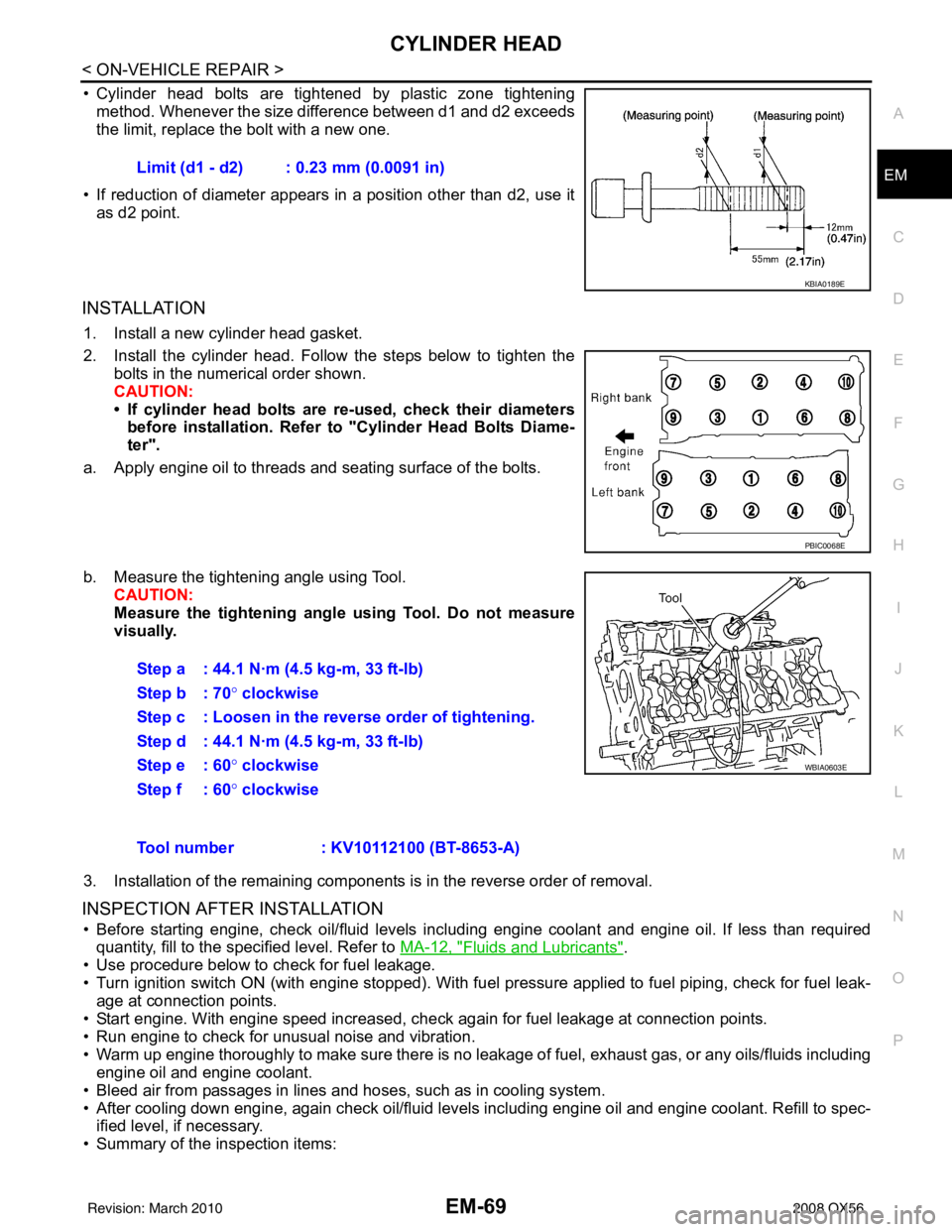
• Cylinder head bolts are tightened by plastic zone tightening
method. Whenever the size difference between d1 and d2 exceeds
the limit, replace the bolt with a new one.
• If reduction of diameter appears in a position other than d2, use it as d2 point.
INSTALLATION
1. Install a new cylinder head gasket.
2. Install the cylinder head. Follow the steps below to tighten the bolts in the numerical order shown.
CAUTION:
• If cylinder head bolts are re-used, check their diameters
before installation. Refer to "Cylinder Head Bolts Diame-
ter".
a. Apply engine oil to threads and seating surface of the bolts.
b. Measure the tightening angle using Tool. CAUTION:
Measure the tightening angl e using Tool. Do not measure
visually.
3. Installation of the remaining components is in the reverse order of removal.
INSPECTION AFTER INSTALLATION
• Before starting engine, check oil/fluid levels incl uding engine coolant and engine oil. If less than required
quantity, fill to the specified level. Refer to MA-12, "
Fluids and Lubricants".
• Use procedure below to check for fuel leakage.
• Turn ignition switch ON (with engine stopped). With fuel pressure applied to fuel piping, check for fuel leak-
age at connection points.
• Start engine. With engine speed increased, check again for fuel leakage at connection points.
• Run engine to check for unusual noise and vibration.
• Warm up engine thoroughly to make sure there is no leak age of fuel, exhaust gas, or any oils/fluids including
engine oil and engine coolant.
• Bleed air from passages in lines and hoses, such as in cooling system.
• After cooling down engine, again check oil/fluid levels including engine oil and engine coolant. Refill to spec- ified level, if necessary.
• Summary of the inspection items: Limit (d1 - d2) : 0.23 mm (0.0091 in)
KBIA0189E
PBIC0068E
Step a : 44.1 N·m (4.5 kg-m, 33 ft-lb)
Step b : 70°
clockwise
Step c : Loosen in the reverse order of tightening.
Step d : 44.1 N·m (4.5 kg-m, 33 ft-lb)
Step e : 60 ° clockwise
Step f : 60° clockwise
WBIA0603E
Tool number : KV10112100 (BT-8653-A)
Revision: March 2010 2008 QX56
Page 1879 of 4083
EM-76
< ON-VEHICLE REPAIR >
CYLINDER HEAD
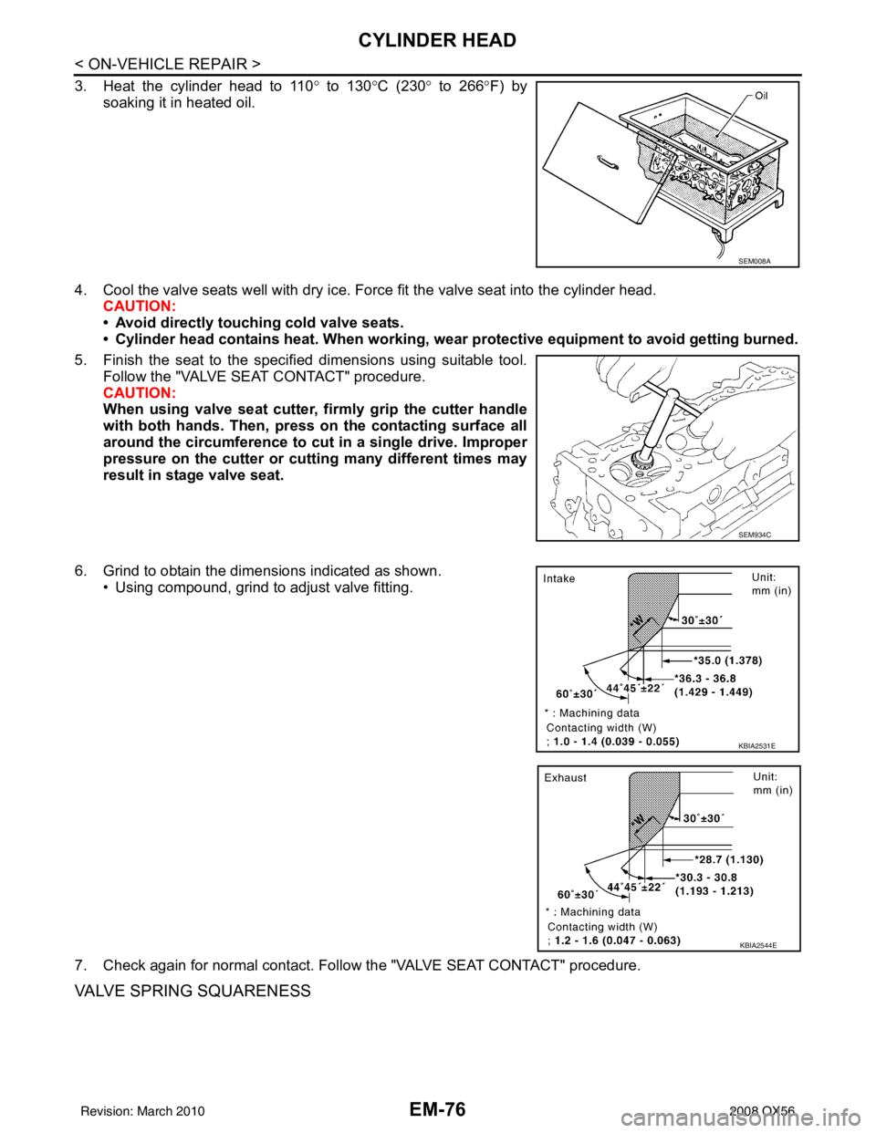
3. Heat the cylinder head to 110° to 130° C (230° to 266° F) by
soaking it in heated oil.
4. Cool the valve seats well with dry ice. Force fit the valve seat into the cylinder head. CAUTION:
• Avoid directly touching cold valve seats.
• Cylinder head contains heat. When working, wear protective eq uipment to avoid getting burned.
5. Finish the seat to the specified dimensions using suitable tool. Follow the "VALVE SEAT CONTACT" procedure.
CAUTION:
When using valve seat cutter, firmly grip the cutter handle
with both hands. Then, pr ess on the contacting surface all
around the circumference to cu t in a single drive. Improper
pressure on the cutter or cutting many different times may
result in stage valve seat.
6. Grind to obtain the dimensions indicated as shown. • Using compound, grind to adjust valve fitting.
7. Check again for normal contact. Follow the "VALVE SEAT CONTACT" procedure.
VALVE SPRING SQUARENESS
SEM008A
SEM934C
KBIA2531E
KBIA2544E
Revision: March 2010 2008 QX56
Page 1883 of 4083
EM-80
< REMOVAL AND INSTALLATION >
ENGINE ASSEMBLY
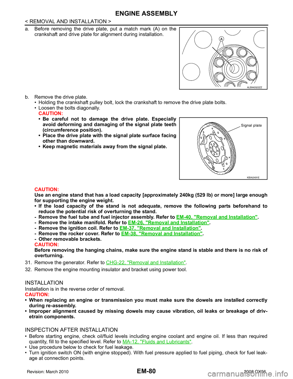
a. Before removing the drive plate, put a match mark (A) on thecrankshaft and drive plate for alignment during installation.
b. Remove the drive plate. • Holding the crankshaft pulley bolt, lock the crankshaft to remove the drive plate bolts.
• Loosen the bolts diagonally.
CAUTION:
• Be careful not to damage the drive plate. Especiallyavoid deforming and damaging of the signal plate teeth
(circumference position).
• Place the drive plate with th e signal plate surface facing
other than downward.
• Keep magnetic materials away from the signal plate.
CAUTION:
Use an engine stand that has a load capacity [a pproximately 240kg (529 lb) or more] large enough
for supporting the engine weight.
• If the load capacity of the stand is not adeq uate, remove the following parts beforehand to
reduce the potential risk of overturning the stand.
- Remove the fuel tube and fuel injector assembly. Refer to EM-40, "
Removal and Installation".
- Remove the intake manifold. Refer to EM-26, "
Removal and Installation".
- Remove the ignition coil. Refer to EM-37, "
Removal and Installation".
- Remove the rocker cover. Refer to EM-38, "
Removal and Installation".
- Other removable brackets.
CAUTION:
Before removing the hanging chains, make sure th e engine stand is stable and there is no risk of
overturning.
31. Remove the generator. Refer to CHG-22, "
Removal and Installation".
32. Remove the engine mounting insulator and bracket using power tool.
INSTALLATION
Installation is in the reverse order of removal.
CAUTION:
• When replacing an engine or transmission you mu st make sure the dowels are installed correctly
during re-assembly.
• Improper alignment caused by mi ssing dowels may cause vibration, oil leaks or breakage of driv-
etrain components.
INSPECTION AFTER INSTALLATION
• Before starting engine, check oil/fluid levels incl uding engine coolant and engine oil. If less than required
quantity, fill to the specified level. Refer to MA-12, "
Fluids and Lubricants".
• Use procedure below to check for fuel leakage.
• Turn ignition switch ON (with engine stopped). With fuel pressure applied to fuel piping, check for fuel leak- age at connection points.
ALBIA0522ZZ
KBIA2491E
Revision: March 2010 2008 QX56