2008 INFINITI QX56 check engine
[x] Cancel search: check enginePage 1928 of 4083

EXHAUST SYSTEMEX-7
< ON-VEHICLE REPAIR >
C
DE
F
G H
I
J
K L
M A
EX
NP
O• Discard any heated oxygen sensor which has been dr
opped from a height of more than 0.5 m (19.7
in) onto a hard surface such as a co ncrete floor; replace with a new one.
• Do not over-torque the heated oxygen sensor. Doing so may damage the heated oxygen sensor,
resulting in the MIL coming on.
• If any mounting insulator is badly deformed, repair or replace it. If deposits such as mud pile up on
the mounting insulators, clean and inspect them.
• Temporarily tighten the nuts on the exhaust manifold side and th e bolts on the vehicle side. Check
each part for interference with other components, an d then tighten the nuts and bolts to specifica-
tion.
INSPECTION AFTER INSTALLATION
• With the engine running, check exhaust tube joints for gas leakage and unusual noises.
• Check to ensure that mounting brackets and mount ing rubbers are installed properly and free from undue
stress. Improper installation could resu lt in excessive noise and vibration.
Tool number A: — (J-43897-18)
B: — (J-43897-12)
Revision: March 2010 2008 QX56
Page 1930 of 4083

EXL-2
HEADLAMP (HI) CIRCUIT ................................28
Description ........................................................... ...28
Component Function Check ...................................28
Diagnosis Procedure ..............................................28
HEADLAMP (LO) CIRCUIT ...............................30
Description ........................................................... ...30
Component Function Check ...................................30
Diagnosis Procedure ..............................................30
FRONT FOG LAMP CIRCUIT ...........................32
Description ........................................................... ...32
Component Function Check ...................................32
Diagnosis Procedure ..............................................32
PARKING LAMP CIRCUIT ................................34
Description ........................................................... ...34
Component Function Check ...................................34
Diagnosis Procedure ..............................................34
TURN SIGNAL LAMP CIRCUIT ........................37
Description ........................................................... ...37
Component Function Check ...................................37
Diagnosis Procedure ..............................................37
OPTICAL SENSOR ...........................................40
Description ..............................................................40
Component Function Check ...................................40
Diagnosis Procedure ..............................................40
HEADLAMP AIMING SWITCH ..........................42
Description ........................................................... ...42
Diagnosis Procedure ..............................................42
HEADLAMP .......................................................43
Wiring Diagram .................................................... ...43
DAYTIME LIGHT SYSTEM ................................47
Wiring Diagram .................................................... ...47
AUTO LIGHT SYSTEM ......................................54
Wiring Diagram .................................................... ...54
HEADLAMP AIMING SYSTEM (MANUAL) ......61
Wiring Diagram .................................................... ...61
FRONT FOG LAMP SYSTEM ...........................65
Wiring Diagram .................................................... ...65
TURN SIGNAL AND HAZARD WARNING
LAMP SYSTEM .............................................. ...
68
Wiring Diagram .................................................... ...68
PARKING, LICENSE PLATE AND TAIL
LAMPS SYSTEM ............................................ ...
75
Wiring Diagram .................................................... ...75
STOP LAMP ......................................................81
Wiring Diagram .................................................... ...81
BACK-UP LAMP ................................................85
Wiring Diagram .................................................... ...85
TRAILER TOW ..................................................90
Wiring Diagram .................................................... ...90
ECU DIAGNOSIS .......................................99
BCM (BODY CONTROL MODULE) ............... ...99
Description ........................................................... ...99
IPDM E/R (INTELLIGENT POWER DISTRI-
BUTION MODULE ENGINE ROOM) ................
100
Description ........................................................... .100
SYMPTOM DIAGNOSIS ...........................101
EXTERIOR LIGHTING SYSTEM SYMPTOMS ..101
Symptom Table .................................................... .101
NORMAL OPERATING CONDITION ...............103
Description ........................................................... .103
BOTH SIDE HEADLAMPS DO NOT SWITCH
TO HIGH BEAM ................................................
104
Description ........................................................... .104
Diagnosis Procedure .............................................104
BOTH SIDE HEADLAMPS (LO) ARE NOT
TURNED ON .....................................................
105
Description ............................................................105
Diagnosis Procedure .............................................105
PARKING, LICENSE PLATE AND TAIL
LAMPS ARE NOT TURNED ON ......................
106
Description ........................................................... .106
Diagnosis Procedure .............................................106
BOTH SIDE FRONT FOG LAMPS ARE NOT
TURNED ON .....................................................
107
Description ............................................................107
Diagnosis Procedure .............................................107
PRECAUTION ...........................................108
PRECAUTIONS .............................................. ..108
Precaution for Supplemental Restraint System
(SRS) "AIR BAG" and "SEAT BELT PRE-TEN-
SIONER" .............................................................. .
108
Precaution Necessary for Steering Wheel Rota-
tion After Battery Disconnect ................................
108
ON-VEHICLE REPAIR ..............................110
ADJUSTMENT AND INSPECTION ................ ..110
HEADLAMP ............................................................ .110
HEADLAMP : Aiming Adjustment .........................110
FRONT FOG LAMP ................................................ .111
FRONT FOG LAMP : Aiming Adjustment .............111
REMOVAL AND INSTALLATION .............113
HEADLAMP .................................................... ..113
Revision: March 2010 2008 QX56
Page 1956 of 4083
EXL-28
< COMPONENT DIAGNOSIS >
HEADLAMP (HI) CIRCUIT
HEADLAMP (HI) CIRCUIT
DescriptionINFOID:0000000001547125
The IPDM E/R (intelligent power distribution module engine room) controls the headlamp high relay based on
inputs from the BCM via the CAN communication lines. When the headlamp high relay is energized, power
flows through fuses 34 and 35, located in the IPDM E/R. Power then flows to the front combination lamps to
the headlamp high beam.
Component Function CheckINFOID:0000000001547126
1.CHECK HEADLAMP (HI) OPERATION
WITHOUT CONTULT-III
1. Start IPDM E/R auto active test. Refer to PCS-12, "
Diagnosis Description".
2. Check that the headlamp switches to the high beam. NOTE:
HI/LO is repeated 1 second each when usi ng the IPDM E/R auto active test.
CONSULT-III
1. Select "EXTERNAL LAMP" of IPDM E/R active test item.
2. With the test item operating, check that the headlamp switches to high beam.
Does the headlamp switch to high beam?
YES >> Headlamp (HI) circuit is normal.
NO >> Refer to EXL-28, "
Diagnosis Procedure".
Diagnosis ProcedureINFOID:0000000001547127
1.CHECK HEADLAMP (HI) FUSES
1. Turn the ignition switch OFF.
2. Check that the following fuses are not open.
Is the fuse open?
YES >> Repair the harness and replace the fuse.
NO >> GO TO 2
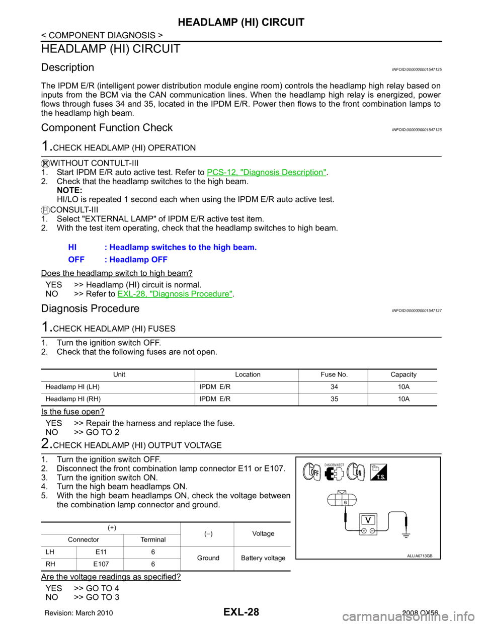
2.CHECK HEADLAMP (HI) OUTPUT VOLTAGE
1. Turn the ignition switch OFF.
2. Disconnect the front combination lamp connector E11 or E107.
3. Turn the ignition switch ON.
4. Turn the high beam headlamps ON.
5. With the high beam headlamps ON, check the voltage between the combination lamp connector and ground.
Are the voltage readings as specified?
YES >> GO TO 4
NO >> GO TO 3 HI : Headlamp switches to the high beam.
OFF : Headlamp OFF
Unit
LocationFuse No.Capacity
Headlamp HI (LH) IPDM E/R3410A
Headlamp HI (RH) IPDM E/R3510A
(+)
(−)Voltage
Connector Terminal
LH E11 6
Ground Battery voltage
RH E107 6
ALLIA0713GB
Revision: March 2010 2008 QX56
Page 1958 of 4083
EXL-30
< COMPONENT DIAGNOSIS >
HEADLAMP (LO) CIRCUIT
HEADLAMP (LO) CIRCUIT
DescriptionINFOID:0000000001547128
The IPDM E/R (intelligent power distribution module engine room) controls the headlamp low relay based on
inputs from the BCM via the CAN communication lines. When the headlamp low relay is energized, power
flows through fuses 40 and 41, located in the IPDM E/R. Power then flows to the front combination lamps to
the headlamp low beam.
Component Function CheckINFOID:0000000001547129
1.CHECK HEADLAMP (LO) OPERATION
WITHOUT CONSULT-III
1. Start IPDM E/R auto active test. Refer to PCS-12, "
Diagnosis Description".
2. Check that the headlamp is turned ON. NOTE:
HI/LO is repeated 1 second each when usi ng the IPDM E/R auto active test.
CONSULT-III
1. Select "EXTERNAL LAMP" of IPDM E/R active test item.
2. With the test items operating, check that the headlamp is turned ON.
Is the headlamp turned ON?
YES >> Headlamp (LO) is normal.
NO >> Refer to EXL-30, "
Diagnosis Procedure".
Diagnosis ProcedureINFOID:0000000001547130
1.CHECK HEADLAMP (LO) FUSES
1. Turn the ignition switch OFF.
2. Check that the following fuses are not open.
Is the fuse open?
YES >> Repair the harness and replace the fuse.
NO >> GO TO 2
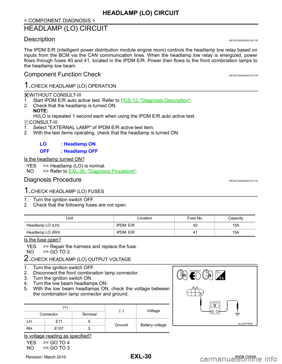
2.CHECK HEADLAMP (LO) OUTPUT VOLTAGE
1. Turn the ignition switch OFF.
2. Disconnect the front combination lamp connector.
3. Turn the ignition switch ON.
4. Turn the low beam headlamps ON.
5. With the low beam headlamps ON, check the voltage between the combination lamp connector and ground.
Is voltage reading as specified?
YES >> GO TO 4
NO >> GO TO 3 LO : Headlamp ON
OFF : Headlamp OFF
Unit
LocationFuse No.Capacity
Headlamp LO (LH) IPDM E/R4015A
Headlamp LO (RH) IPDM E/R4115A
(+)
(−)Voltage
Connector Terminal
LH E11 5 Ground Battery voltage
RH E107 5
ALLIA0716GB
Revision: March 2010 2008 QX56
Page 1960 of 4083
EXL-32
< COMPONENT DIAGNOSIS >
FRONT FOG LAMP CIRCUIT
FRONT FOG LAMP CIRCUIT
DescriptionINFOID:0000000001547131
The IPDM E/R (intelligent power distribution module engine room) controls the front fog lamp relay based on
inputs from the BCM via the CAN communication lines. When the front fog lamp relay is energized, power
flows from the front fog lamp relay in the IPDM E/R to the front fog lamps.
Component Function CheckINFOID:0000000001547132
1.CHECK FRONT FOG LAMP OPERATION
WITHOUT CONSULT-III
1. Activate IPDM E/R auto active test. Refer to PCS-12, "
Diagnosis Description".
2. Check that the front fog lamp is turned ON.
CONSULT-III
1. Select "EXTERNAL LAMP" of IPDM E/R active test item.
2. With operating the test items, Check that the front fog lamp is turned ON.
Is the front fog lamp turned ON?
YES >> Front fog lamp circuit is normal.
NO >> Refer to EXL-32, "
Diagnosis Procedure".
Diagnosis ProcedureINFOID:0000000001547133
1.CHECK FRONT FOG LAMP FUSE
1. Turn the ignition switch OFF.
2. Check that the following fuses are not open.
Is the fuse open?
YES >> Repair the harness and replace the fuse.
NO >> GO TO 2
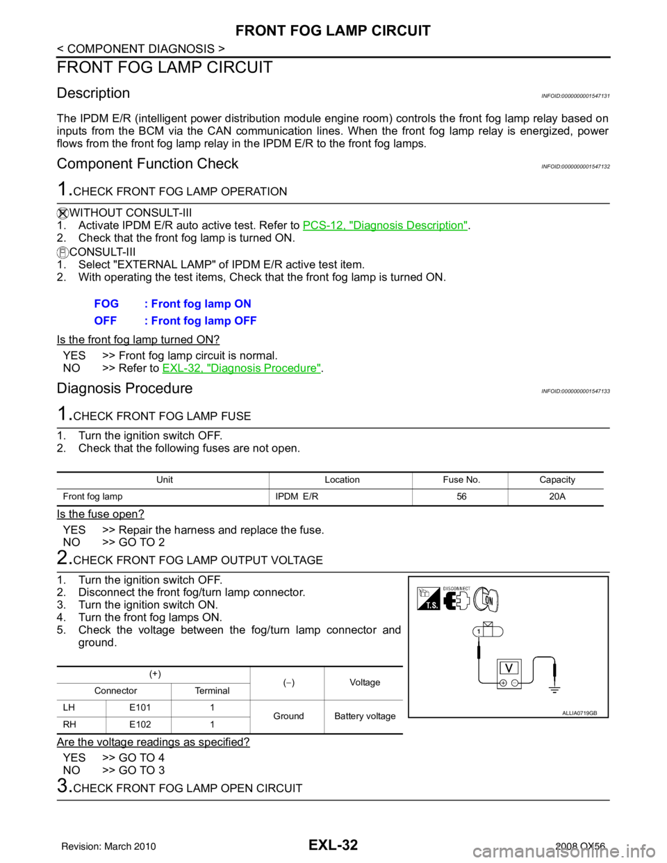
2.CHECK FRONT FOG LAMP OUTPUT VOLTAGE
1. Turn the ignition switch OFF.
2. Disconnect the front fog/turn lamp connector.
3. Turn the ignition switch ON.
4. Turn the front fog lamps ON.
5. Check the voltage between the fog/turn lamp connector and ground.
Are the voltage readings as specified?
YES >> GO TO 4
NO >> GO TO 3
3.CHECK FRONT FOG LAMP OPEN CIRCUIT FOG : Front fog lamp ON
OFF : Front fog lamp OFF
Unit
LocationFuse No.Capacity
Front fog lamp IPDM E/R5620A
(+)
(−)V olt a g e
Connector Terminal
LH E101 1
Ground Battery voltage
RH E102 1
ALLIA0719GB
Revision: March 2010 2008 QX56
Page 1962 of 4083
EXL-34
< COMPONENT DIAGNOSIS >
PARKING LAMP CIRCUIT
PARKING LAMP CIRCUIT
DescriptionINFOID:0000000001547134
The IPDM E/R (intelligent power distribution module engine room) controls the tail lamp relay based on inputs
from the BCM via the CAN communication lines. When the tail lamp relay is energized, power flows through
fuse 37, located in the IPDM E/R. Power then flows to the front and rear combination lamps.
Component Function CheckINFOID:0000000001547135
1.CHECK PARKING LAMP OPERATION
WITHOUT CONSULT-III
1. Activate IPDM E/R auto active test. Refer to PCS-12, "
Diagnosis Description".
2. Check that the parking lamp is turned ON.
CONSULT-III
1. Select "EXTERNAL LAMP" of IPDM E/R active test item.
2. With operating the test items, check that the parking lamp is turned ON.
Is the parking lamp turned ON?
YES >> Parking lamp circuit is normal.
NO >> Refer to EXL-34, "
Diagnosis Procedure".
Diagnosis ProcedureINFOID:0000000001547136
1.CHECK PARKING LAMP FUSES
1. Turn the ignition switch OFF.
2. Check that the following fuses are not open.
Is the fuse open?
YES >> Repair the harness and replace the fuse.
NO >> GO TO 2
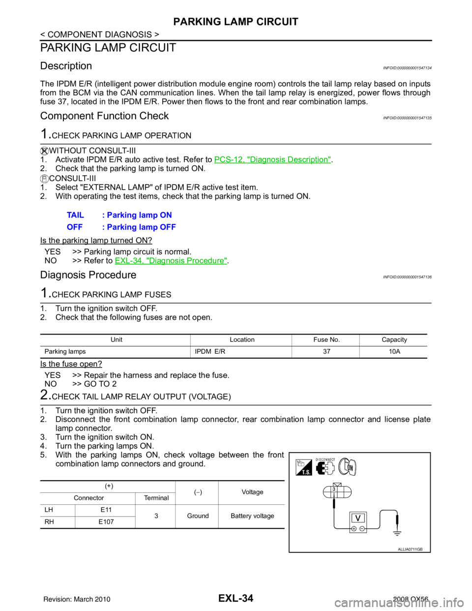
2.CHECK TAIL LAMP RELAY OUTPUT (VOLTAGE)
1. Turn the ignition switch OFF.
2. Disconnect the front combination lamp connector, rear combination lamp connector and license plate
lamp connector.
3. Turn the ignition switch ON.
4. Turn the parking lamps ON.
5. With the parking lamps ON, check voltage between the front combination lamp connectors and ground.TAIL : Parking lamp ON
OFF : Parking lamp OFF
Unit
LocationFuse No.Capacity
Parking lamps IPDM E/R3710A
(+)
(−)Voltage
Connector Terminal
LH E11
3 Ground Battery voltage
RH E107
ALLIA0711GB
Revision: March 2010 2008 QX56
Page 2038 of 4083
EXL-110
< ON-VEHICLE REPAIR >
ADJUSTMENT AND INSPECTION
ON-VEHICLE REPAIR
ADJUSTMENT AND INSPECTION
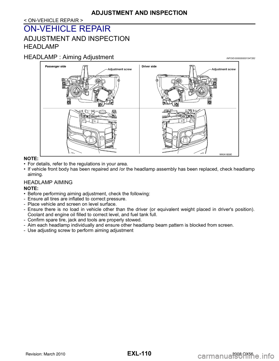
HEADLAMP
HEADLAMP : Aiming AdjustmentINFOID:0000000001547282
NOTE:
• For details, refer to the regulations in your area.
• If vehicle front body has been repaired and /or the headlamp assembly has been replaced, check headlamp
aiming.
HEADLAMP AIMING
NOTE:
• Before performing aiming adjustment, check the following:
- Ensure all tires are inflated to correct pressure.
- Place vehicle and screen on level surface.
- Ensure there is no load in vehicle other than the driver (or equivalent weight placed in driver's position).
Coolant and engine oil filled to correct level, and fuel tank full.
- Confirm spare tire, jack and tools are properly stowed.
- Aim each headlamp individually and ensure other headlamp beam pattern is blocked from screen.
- Use adjusting screw to perform aiming adjustment
WKIA1859E
Revision: March 2010 2008 QX56
Page 2059 of 4083

EXT-6
< SERVICE INFORMATION >
SQUEAK AND RATTLE TROUBLE DIAGNOSES
If the noise can be duplicated easily during the test drive, to help identify the source of the noise, try to dupli-
cate the noise with the vehicle stopped by doing one or all of the following:
1) Close a door.
2) Tap or push/pull around the area where the noise appears to be coming from.
3) Rev the engine.
4) Use a floor jack to recreate vehicle “twist”.
5) At idle, apply engine load (electrical load, half-clutch on M/T model, drive position on A/T model).
6) Raise the vehicle on a hoist and hit a tire with a rubber hammer.
• Drive the vehicle and attempt to duplicate the conditions the customer states exist when the noise occurs.
• If it is difficult to duplicate the noise, drive the v ehicle slowly on an undulating or rough road to stress the
vehicle body.
CHECK RELATED SERVICE BULLETINS
After verifying the customer concern or symptom, chec k ASIST for Technical Service Bulletins (TSBs) related
to that concern or symptom.
If a TSB relates to the symptom, follo w the procedure to repair the noise.
LOCATE THE NOISE AND IDENTIFY THE ROOT CAUSE
1. Narrow down the noise to a general area.To help pinpoint the source of the noise, use a listening tool
(Chassis Ear: J-39570, Engine Ear: J-39565 and mechanic's stethoscope).
2. Narrow down the noise to a more specific area and identify the cause of the noise by:
• removing the components in the area that you suspect the noise is coming from.
Do not use too much force when removing clips and fasteners, otherwise clips and fasteners can be broken
or lost during the repair, resulting in the creation of new noise.
• tapping or pushing/pulling the component that you suspect is causing the noise.
Do not tap or push/pull the component with excessive force, otherwise the noise will be eliminated only tem-
porarily.
• feeling for a vibration with your hand by touching the component(s) that you suspect is (are) causing the
noise.
• placing a piece of paper between components that you suspect are causing the noise.
• looking for loose components and contact marks. Refer to EXT-7, "
Generic Squeak and Rattle Troubleshooting".
REPAIR THE CAUSE
• If the cause is a loose component, tighten the component securely.
• If the cause is insufficient clearance between components:
- separate components by repositioning or loos ening and retightening the component, if possible.
- insulate components with a suitable insulator such as urethane pads, foam blocks, felt cloth tape or urethane tape. A NISSAN Squeak and Rattle Kit (J-43980) is av ailable through your authorized NISSAN Parts Depart-
ment.
CAUTION:
Do not use excessive force as many components are constructed of plastic and may be damaged.
Always check with the Parts Department for the latest parts information.
The following materials are contained in the NISSAN Squeak and Rattle Kit (J-43980). Each item can be
ordered separately as needed.
URETHANE PADS [1.5 mm (0.059 in) thick]
Insulates connectors, harness, etc.
76268-9E005: 100 ×135 mm (3.94× 5.31 in)/76884-71L01: 60 ×85 mm (2.36 ×3.35 in)/76884-71L02: 15 ×25
mm (0.59× 0.98 in)
INSULATOR (Foam blocks)
Insulates components from contact. Can be used to fill space behind a panel.
73982-9E000: 45 mm (1.77 in) thick, 50 ×50 mm (1.97 ×1.97 in)/73982-50Y00: 10 mm (0.39 in) thick,
50× 50 mm (1.97 ×1.97 in)
INSULATOR (Light foam block)
80845-71L00: 30 mm (1.18 in) thick, 30 ×50 mm (1.18 ×1.97 in)
FELT CLOTH TAPE
Used to insulate where movemen t does not occur. Ideal for instrument panel applications.
68370-4B000: 15 ×25 mm (0.59× 0.98 in) pad/68239-13E00: 5 mm (0.20 in ) wide tape roll. The following
materials not found in the kit can also be used to repair squeaks and rattles.
UHMW (TEFLON) TAPE
Insulates where slight movement is present. Ideal for inst rument panel applications.
Revision: March 2010 2008 QX56