2008 INFINITI QX56 transmission
[x] Cancel search: transmissionPage 3727 of 4083
TM-180
< ON-VEHICLE MAINTENANCE >
A/T FLUID
Changing the A/T Fluid (ATF)
INFOID:0000000004917425
CAUTION:
If using the vehicle for towing, the A/T fl uid must be replaced as specified. Refer to MA-8, "
Introduc-
tion of Periodic Maintenance".
1. Drive the vehicle to warm up the A/T fluid to approximately 80 ° C (176 ° F).
2. Stop the engine.
3. Remove the A/T fluid level gauge.
4. Drain the A/T fluid from the drain plug hole, then install the drain plug with a new gasket. Refill the transmission with new A/T
fluid. Always refill with the same volume as the drained A/T fluid.
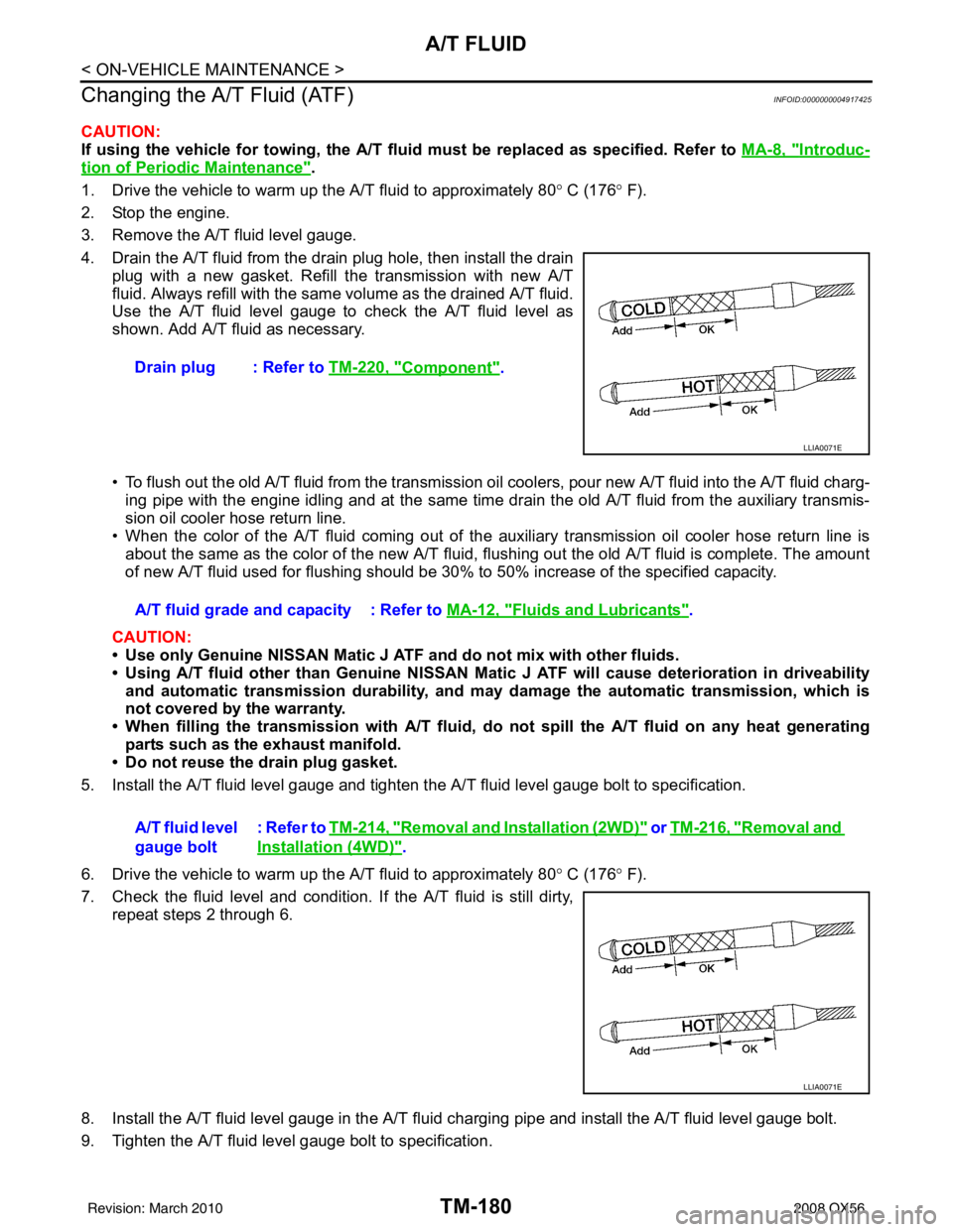
Use the A/T fluid level gauge to check the A/T fluid level as
shown. Add A/T fluid as necessary.
• To flush out the old A/T fluid from the transmission oil coolers, pour new A/T fluid into the A/T fluid charg-
ing pipe with the engine idling and at the same time drain the old A/T fluid from the auxiliary transmis-
sion oil cooler hose return line.
• When the color of the A/T fluid coming out of the auxiliary transmission oil cooler hose return line is
about the same as the color of the new A/T fluid, flushing out the old A/T fluid is complete. The amount
of new A/T fluid used for flushing should be 30% to 50% increase of the specified capacity.
CAUTION:
• Use only Genuine NISSAN Matic J ATF and do not mix with other fluids.
• Using A/T fluid other than Genuine NISSAN Mati c J ATF will cause deterioration in driveability
and automatic transmission durability, and may damage the automatic transmission, which is
not covered by the warranty.
• When filling the transmission with A/T fluid, do not spill the A/T fluid on any heat generating parts such as the exhaust manifold.
• Do not reuse the drain plug gasket.
5. Install the A/T fluid level gauge and tighten the A/T fluid level gauge bolt to specification.
6. Drive the vehicle to warm up the A/T fluid to approximately 80 ° C (176 ° F).
7. Check the fluid level and condition. If the A/T fluid is still dirty, repeat steps 2 through 6.
8. Install the A/T fluid level gauge in the A/T fluid charging pipe and install the A/T fluid level gauge bolt.
9. Tighten the A/T fluid level gauge bolt to specification. Drain plug : Refer to
TM-220, "
Component".
LLIA0071E
A/T fluid grade and capacity : Refer to MA-12, "Fluids and Lubricants".
A/T fluid level
gauge bolt : Refer to TM-214, "
Removal and Installation (2WD)" or TM-216, "Removal and
Installation (4WD)".
LLIA0071E
Revision: March 2010
2008 QX56
Page 3729 of 4083
TM-182
< ON-VEHICLE MAINTENANCE >
A/T FLUID COOLER
A/T FLUID COOLER
A/T Fluid Cooler CleaningINFOID:0000000004917426
Whenever an A/T is repaired, overhauled, or replaced, the A/T fluid cooler mounted in the radiator must be
inspected and cleaned.
Metal debris and friction material, if present, can become trapped in the A/T fluid cooler. This debris can con-
taminate the newly serviced A/T or, in severe cases, can bloc k or restrict the flow of A/T fluid. In either case,
malfunction of the newly serviced A/T may result.
Debris, if present, may build up as A/T fluid enters the c ooler inlet. It will be necessary to back flush the cooler
through the cooler outlet in order to flush out any built up debris.
A/T FLUID COOLER CLEANING PROCEDURE
1. Position a drain pan under the A/T inlet and outlet fluid cooler tube to cooler hose connection.
2. Put a different color matching mark on each cooler tube to cooler hose connection to aid in assembly. CAUTION:
Use paint to make the matching mark. Do not damage the tubes or hose.
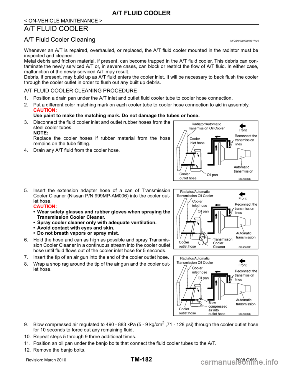
3. Disconnect the fluid cooler inlet and outlet rubber hoses from the steel cooler tubes.
NOTE:
Replace the cooler hoses if rubber material from the hose
remains on the tube fitting.
4. Drain any A/T fluid from the cooler hose.
5. Insert the extension adapter hose of a can of Transmission
Cooler Cleaner (Nissan P/N 999MP-AM006) into the cooler out-
let hose.
CAUTION:
• Wear safety glasses and rubber gloves when spraying the Transmission Cooler Cleaner.
• Spray cooler cleaner only wi th adequate ventilation.
• Avoid contact with eyes and skin.
• Do not breath vapors or spray mist.
6. Hold the hose and can as high as possible and spray Transmis- sion Cooler Cleaner in a continuous stream into the cooler outlet
hose until fluid flows out of the cooler inlet hose for 5 seconds.
7. Insert the tip of an air gun into the end of the cooler outlet hose.
8. Wrap a shop rag around the tip of the air gun and the cooler out- let hose.
9. Blow compressed air regulated to 490 - 883 kPa (5 - 9 kg/cm
2 ,71 - 128 psi) through the cooler outlet hose
for 10 seconds to force out any remaining fluid.
10. Repeat steps 5 through 9 three additional times.
11. Position an oil pan under the banjo bolts that connect the fluid cooler tubes to the A/T.
12. Remove the banjo bolts.
SCIA3830E
SCIA3831E
SCIA3832E
Revision: March 2010 2008 QX56
Page 3730 of 4083
A/T FLUID COOLERTM-183
< ON-VEHICLE MAINTENANCE >
CEF
G H
I
J
K L
M A
B
TM
N
O P
13. Flush each steel line from the cooler side back toward the A/T by spraying Transmission Cooler Cleaner in a continuous stream for 5 seconds.
14. Blow compressed air regulated to 490 - 883 kPa (5 - 9 kg/cm
2 ,71 - 128 psi) through each steel line from
the cooler side back toward the A/T for 10 seconds to force out any remaining fluid.
15. Ensure all debris is removed from the steel cooler lines.
16. Ensure all debris is removed from the banjo bolts and fittings.
17. Perform A/T fluid cooler diagnosis procedure.
A/T FLUID COOLER DIAGNOSIS PROCEDURE
NOTE:
Insufficient cleaning of the cooler inlet hose exte rior may lead to inaccurate debris identification.
1. Position a drain pan under the A/T inlet and outlet fluid cooler tube to cooler hose connection.
2. Clean the exterior and tip of the cooler inlet hose.
3. Put a different color matching mark on each cooler tube to cooler hose connection to aid in assembly. CAUTION:
Use paint to make the matching mark. Do not damage the tubes or hose.
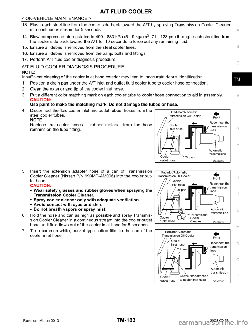
4. Disconnect the fluid cooler inle t and outlet rubber hoses from the
steel cooler tubes.
NOTE:
Replace the cooler hoses if rubber material from the hose
remains on the tube fitting.
5. Insert the extension adapter hose of a can of Transmission Cooler Cleaner (Nissan P/N 999MP-AM006) into the cooler out-
let hose.
CAUTION:
• Wear safety glasses and rubber gloves when spraying the
Transmission Cooler Cleaner.
• Spray cooler cleaner only with adequate ventilation.
• Avoid contact with eyes and skin.
• Do not breath vapors or spray mist.
6. Hold the hose and can as high as possible and spray Transmis- sion Cooler Cleaner in a continuous stream into the cooler outlet
hose until fluid flows out of the cooler inlet hose for 5 seconds.
7. Tie a common white, basket-type coffee filter to the end of the cooler inlet hose.
SCIA3830E
SCIA3831E
SCIA3833E
Revision: March 2010 2008 QX56
Page 3736 of 4083
ROAD TESTTM-189
< ON-VEHICLE MAINTENANCE >
CEF
G H
I
J
K L
M A
B
TM
N
O P
ROAD TEST
DescriptionINFOID:0000000001696158
ROAD TEST
• The road test inspects overall performance of the A/T and analyzes possible malfunction causes.
• The road test is carried out in the following three stages.
1. Check before engine is started. Refer to TM-189
.
2. Check at idle. Refer to TM-189
.
3. Cruise test • Inspect all the items from Part 1 to Part 3. Refer to TM-190
, TM-192, TM-193.
• Before beginning the road test, check the test procedure and inspection items.
• Test all inspection items until the symptom is uncov ered. Diagnose NG items when all road tests are com-
plete.
Check Before Engine Is StartedINFOID:0000000001696159
1.CHECK AT CHECK INDICATOR LAMP
1. Park vehicle on level surface.
2. Move selector lever to “P” position.
3. Turn ignition switch to “OFF” position and wait at least 10 seconds.
4. Turn ignition switch to “ON” position. (Do not start engine.)
Does AT CHECK indicator lamp light up for about 2 seconds?
YES >> 1. Turn ignition switch to “OFF” position. 2. Carry out the self-diagnostics and record all NG items on the diagnostics worksheet. Refer toTM-32, "
CONSULT-III Function (TRANSMISSION)".
3. Go to TM-189, "
Check At Idle".
NO >> Stop the road test and go to TM-118, "
A/T Check Indicator Lamp Does Not Come On".
Check At IdleINFOID:0000000001696160
1.CHECK STARTING THE ENGINE
1. Park vehicle on level surface.
2. Move selector lever to “P” or “N” position.
3. Turn ignition switch to “OFF” position.
4. Turn ignition switch to “START” position.
Does the engine start?
YES >> GO TO 2.
NO >> Stop the road test and go to TM-118, "
Engine Cannot Be Started in "P" or "N" Position".
2.CHECK STARTING THE ENGINE
1. Turn ignition switch to “ON” position.
2. Move selector lever in “D”,“4”, “3”, “2”, “1” or “R” position.
3. Turn ignition switch to “START” position.
Does the engine start in either position?
YES >> Stop the road test and go to TM-118, "Engine Cannot Be Started in "P" or "N" Position".
NO >> GO TO 3.
3.CHECK “P” POSITION FUNCTIONS
1. Move selector lever to “P” position.
2. Turn ignition switch to “OFF” position.
3. Release the parking brake.
4. Push the vehicle forward or backward.
5. Engage the parking brake.
When you push the vehicle with disengaging the parking brake, does it move?
Revision: March 2010 2008 QX56
Page 3737 of 4083
TM-190
< ON-VEHICLE MAINTENANCE >
ROAD TEST
YES >> Enter a check mark at “In “P” Position Vehicle Moves When Pushed” on the diagnostics work-sheet, then continue the road test.
NO >> GO TO 4.
4.CHECK “N” POSITION FUNCTIONS
1. Start the engine.
2. Move selector lever to “N” position.
3. Release the parking brake.
Does vehicle move forward or backward?
YES >> Enter a check mark at “In “N” Position Vehicle Moves” on the diagnostics worksheet, then con- tinue the road test.
NO >> GO TO 5.
5.CHECK SHIFT SHOCK
1. Engage the brake.
2. Move selector lever to “D” position.
When the transmission is shifted from
“N” to “D”, is there an excessive shock?
YES >> Enter a check mark at “Large Shock ("N" to "D" Position) on the diagnostics worksheet, then con-
tinue the road test.
NO >> GO TO 6.
6.CHECK “R” POSITION FUNCTIONS
1. Engage the brake.
2. Move selector lever to “R” position.
3. Release the brake for 4 to 5 seconds.
Does the vehicle creep backward?
YES >> GO TO 7.
NO >> Enter a check mark at “Vehicle Does Not Creep Backward In "R" Position” on the diagnostics
worksheet, then continue the road test.
7.CHECK “D” POSITION FUNCTIONS
Inspect whether the vehicle creeps forward when the transmission is put into the “D” position.
Does the vehicle creep forward in the
“D” positions?
YES >> Go to TM-190, "Cruise Test - Part 1", TM-192, "Cruise Test - Part 2", and TM-193, "Cruise Test -
Part 3".
NO >> Enter a check mark at “Vehicle Does Not Cr eep Forward in "D" Position” on the diagnostics work-
sheet, then continue the road test.
Cruise Test - Part 1INFOID:0000000001696161
1.CHECK STARTING OUT FROM D1
1. Drive the vehicle for about 10 minutes to warm up the engine oil and ATF. Appropriate temperature for the ATF: 50 - 80° C (122 - 176°F)
2. Park the vehicle on a level surface.
3. Move selector lever to “P” position.
4. Start the engine.
5. Move selector lever to “D” position.
6. Press the accelerator pedal about half way down to accelerate the vehicle.
With CONSULT-III
Read off the gear positions.
Starts from D1?
YES >> GO TO 2.
NO >> Enter a check mark at “Vehicle Cannot be St arted From D1” on the diagnostics worksheet, then
continue the road test.
2.CHECK SHIFT-UP D1 → D2
Press down the accelerator pedal about half way and inspect if the vehicle shifts up (D1 → D2) at the appropri-
ate speed.
Revision: March 2010 2008 QX56
Page 3739 of 4083
TM-192
< ON-VEHICLE MAINTENANCE >
ROAD TEST
NO >> Enter a check mark at “A/T Does Not Hold Lock-up Condition” on the diagnostics worksheet, thencontinue the road test.
8.CHECK LOCK-UP RELEASE
Check lock-up cancellation by depressing brake pedal lightly to decelerate. With CONSULT-III
Select “TCC SOLENOID 0.00A” with the “MAIN SIGNAL” mode for A/T.
Does lock-up cancel?
YES >> GO TO 9.
NO >> Enter a check mark at “Lock-up Is Not Released” on the diagnostics worksheet, then continue the road test.
9.CHECK SHIFT-DOWN D5 → D4
Decelerate by pressing lightly on the brake pedal. With CONSULT-III
Read the gear position and engine speed.
When the A/T shift-down D5
→ D4, does the engine speed drop smoothly back to idle?
YES >> 1. Stop the vehicle. 2. Go to Cruise test - Part 2 (Refer to AT 58).
NO >> Enter a check mark at “Engine Speed Does Not Return to Idle” on the diagnostics worksheet, then continue the road test. Go to Cruise test - Part 2 (Refer to AT 58).
Cruise Test - Part 2INFOID:0000000001696162
1.CHECK STARTING FROM D1
1. Move selector lever the “D” position.
2. Accelerate at half throttle. With CONSULT-III
Read the gear position.
Does it start from D1?
YES >> GO TO 2.
NO >> Enter a check mark at “Vehicle Cannot Be Started From D1” on the diagnostics worksheet, then continue the road test.
2.CHECK SHIFT-UP D1 → D2
Press the accelerator pedal down all the way and ins pect whether or not the transmission shifts up (D1 → D2)
at the correct speed.
• Refer to TM-291, "
Vehicle Speed at Which Gear Shifting Occurs".
With CONSULT-III
Read the gear position, throttle position and vehicle speed.
Does the A/T shift-up D1
→ D2 at the correct speed?
YES >> GO TO 3.
NO >> Enter a check mark at “Vehicle Does Not Shift: D1 → D2” on the diagnostics worksheet, then con-
tinue the road test.
3.CHECK SHIFT-UP D2 → D3
Press the accelerator pedal down all the way and ins pect whether or not the transmission shifts up (D2 → D3)
at the correct speed.
• Refer to TM-291, "
Vehicle Speed at Which Gear Shifting Occurs".
With CONSULT-III
Read the gear position, throttle position and vehicle speed.
Does the A/T shift-up D2
→ D3 at the correct speed?
YES >> GO TO 4.
NO >> Enter a check mark at “Vehicle Does Not Shift: D2 → D3” on the diagnostics worksheet, then con-
tinue the road test.
4.CHECK SHIFT-UP D3 → D4 AND ENGINE BRAKE
Revision: March 2010 2008 QX56
Page 3740 of 4083
ROAD TESTTM-193
< ON-VEHICLE MAINTENANCE >
CEF
G H
I
J
K L
M A
B
TM
N
O P
When the transmission changes speed D3 → D4, return the accelerator pedal.
Does the A/T shift-up D3
→ D4 and apply the engine brake?
YES >> 1. Stop the vehicle. 2. See TM-193, "
Cruise Test - Part 3".
NO >> Enter a check mark at “Vehicle Does Not Shift: D3 → D4” on the diagnostics worksheet, then con-
tinue the road test.
Cruise Test - Part 3INFOID:0000000001696163
1.CHECK SHIFT-DOWN
During D
5 driving, move gear selector from D → 4 → 3 → 2 → 1.
With CONSULT-III
Read the gear position.
Is downshifting correctly performed?
YES >> GO TO 2.
NO >> Enter a check mark at “Vehicle does not shift” at the corresponding position (5th → 4th, 4th → 3rd,
3rd → 2nd, 2nd → 1st) on the diagnostics worksheet, then continue the road test.
2.CHECK ENGINE BRAKE
Does engine braking effectively reduce speed in 1
1 position?
YES >> 1. Stop the vehicle. 2. Carry out the self-diagnostics. Refer to TM-32, "
CONSULT-III Function (TRANSMISSION)".
NO >> Enter a check mark at “Vehicle Does Not Decelerate By Engine Brake” on the diagnostics work- sheet, then continue trouble diagnosis.
Vehicle Speed When Shifting GearsINFOID:0000000001696164
Refer to TM-193, "Vehicle Speed When Shifting Gears".
Vehicle Speed When Performing and Releasing Complete Lock-upINFOID:0000000001696165
Refer to TM-193, "Vehicle Speed When Performing and Releasing Complete Lock-up".
Revision: March 2010 2008 QX56
Page 3741 of 4083
TM-194
< ON-VEHICLE MAINTENANCE >
A/T POSITION
A/T POSITION
Checking of A/T PositionINFOID:0000000004917429
With the shift selector in the “P” position, turn the ignition switch to the ON position with the engine OFF.
Confirm that the following conditions apply.
• The shift selector can be shifted from the “P ” position only when the brake pedal is depressed.
• The shift selector stops at each position with the feel of engagement when it is moved through all the posi-
tions.
• There is no excessive effort, sticking, noise or rattle.
• The actual position of the shift selector matches the position shown by the shift position indicator and the A/
T body.
• The back-up lamps illuminate only when the shift selector is placed in the “R” position.
• The back-up lamps do not illuminate when the shift selector is pushed against the “R” position when in the
“P” or “N” position.
• The engine can only be started with the shift selector in the “P” and “N” positions.
• The A/T is locked completely when in the “P” position.
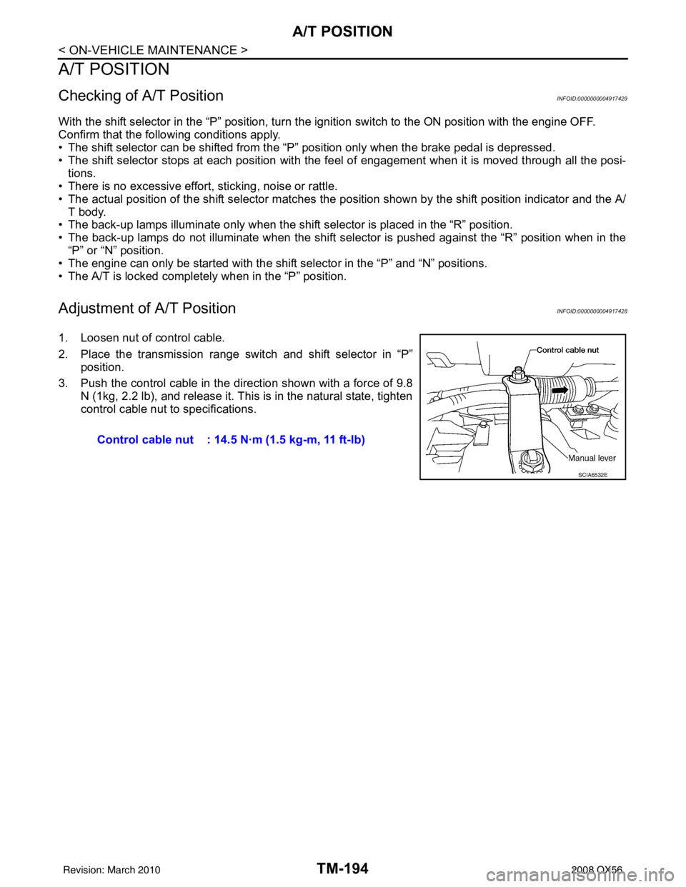
Adjustment of A/T PositionINFOID:0000000004917428
1. Loosen nut of control cable.
2. Place the transmission range switch and shift selector in “P”
position.
3. Push the control cable in the di rection shown with a force of 9.8
N (1kg, 2.2 lb), and release it. This is in the natural state, tighten
control cable nut to specifications.
Control cable nut : 14.5 N·m (1.5 kg-m, 11 ft-lb)
SCIA6532E
Revision: March 2010 2008 QX56