2008 INFINITI QX56 relay
[x] Cancel search: relayPage 3538 of 4083

STARTING SYSTEMSTR-9
< FUNCTION DIAGNOSIS >
C
DE
F
G H
I
J
K L
M A
STR
NP
O
Component DescriptionINFOID:0000000001696227
Component part
Description
TCM TCM supplies power to the starter relay inside the IPDM E/R
when the selector lever is shifted to the P or N position.
BCM BCM sends a starter request signal to the CPU of the IPDM E/R
over the CAN communication lines.
IPDM E/R CPU inside IPDM E/R operates the starter relay at the request of
the BCM over the CAN communication lines.
Starter motor The starter motor plunger closes and the motor is supplied with
battery power, which in turn cranks the engine, when the “S” ter-
minal is supplied with electric power.
Revision: March 2010
2008 QX56
Page 3548 of 4083

TM-1
TRANSMISSION & DRIVELINE
CEF
G H
I
J
K L
M
SECTION TM
A
B
TM
N
O P
CONTENTS
TRANSAXLE & TRANSMISSION
BASIC INSPECTION ....... .............................5
DIAGNOSIS AND REPAIR WORKFLOW ..... .....5
Work Flow ........................................................... ......5
Diagnostic Work Sheet ..............................................6
FUNCTION DIAGNOSIS ...............................8
A/T CONTROL SYSTEM ................................ .....8
Cross-Sectional View (2WD models) .................. ......8
Cross-Sectional View (4WD models) ........................9
Shift Mechanism ........................................................9
TCM Function ..........................................................20
CAN Communication ...............................................21
Input/Output Signal of TCM .....................................22
Line Pressure Control .............................................22
Shift Control ........................................................ ....24
Lock-up Control .......................................................25
Engine Brake Control ..............................................26
Control Valve ...........................................................26
Component Parts Location ......................................28
A/T SHIFT LOCK SYSTEM ............................ ....29
System Description ............................................. ....29
Component Parts Location ......................................29
ON BOARD DIAGNOSTIC (OBD) SYSTEM ......30
Introduction ......................................................... ....30
OBD-II Function for A/T System ..............................30
One or Two Trip Detection Logic of OBD-II ............30
OBD-II Diagnostic Trouble Code (DTC) ..................30
Malfunction Indicator Lamp (MIL) ............................31
DIAGNOSIS SYSTEM (TCM) .............................32
CONSULT-III Function (TRANSMISSION) ......... ....32
COMPONENT DIAGNOSIS .........................38
U1000 CAN COMM CI RCUIT .............................38
Description .......................................................... ....38
On Board Diagnosis Logic ......................................38
Possible Cause .......................................................38
DTC Confirmation Procedure .............................. ....38
Diagnosis Procedure ...............................................38
P0615 STARTER RELAY .................................39
Description ...............................................................39
CONSULT-III Reference Value in Data Monitor
Mode .................................................................... ....
39
On Board Diagnosis Logic .......................................39
Possible Cause ........................................................39
DTC Confirmation Procedure ..................................39
Diagnosis Procedure ...............................................39
P0700 TRANSMISSION CONTROL .................42
Description ...............................................................42
On Board Diagnosis Logic .......................................42
Possible Cause ........................................................42
DTC Confirmation Procedure ..................................42
Diagnosis Procedure ...............................................42
P0705 TRANSMISSION RANGE SWITCH A ...43
Description ...............................................................43
CONSULT-III Reference Value in Data Monitor
Mode .................................................................... ....
43
On Board Diagnosis Logic .......................................43
Possible Cause ........................................................43
DTC Confirmation Procedure ..................................43
Diagnosis Procedure ...............................................43
P0717 INPUT SPEED SENSOR A ....................46
Description ...............................................................46
CONSULT-III Reference Value in Data Monitor
Mode .................................................................... ....
46
On Board Diagnosis Logic .......................................46
Possible Cause ........................................................46
DTC Confirmation Procedure ..................................46
Diagnosis Procedure ...............................................46
P0720 OUTPUT SPEED SENSOR ...................48
Description ...............................................................48
CONSULT-III Reference Value in Data Monitor
Mode .................................................................... ....
48
On Board Diagnosis Logic .......................................48
Revision: March 2010 2008 QX56
Page 3568 of 4083

A/T CONTROL SYSTEMTM-21
< FUNCTION DIAGNOSIS >
CEF
G H
I
J
K L
M A
B
TM
N
O P
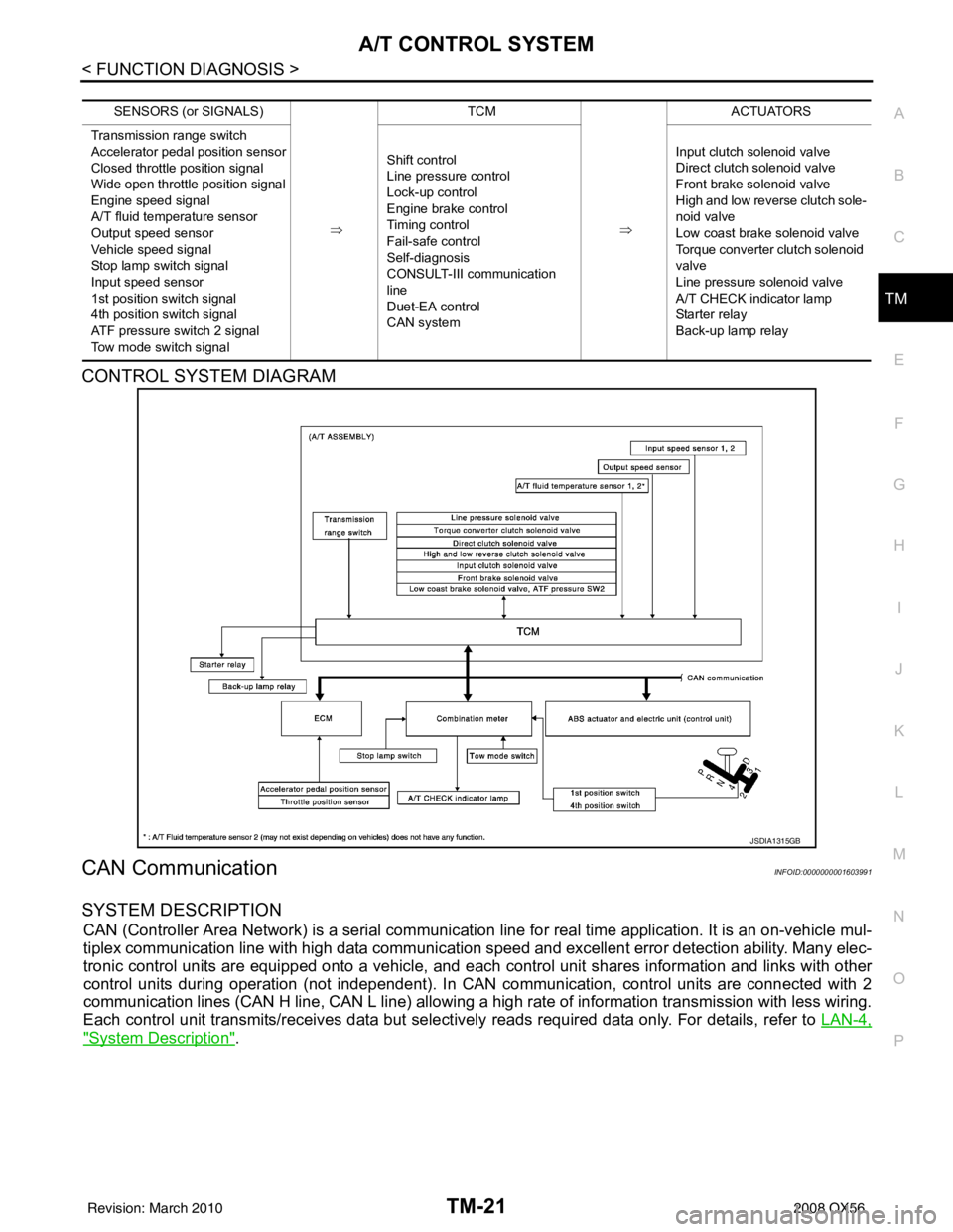
CONTROL SYSTEM DIAGRAM
CAN CommunicationINFOID:0000000001603991
SYSTEM DESCRIPTION
CAN (Controller Area Network) is a serial communication line for real time application. It is an on-vehicle mul-
tiplex communication line with high data communication speed and excellent error detection ability. Many elec-
tronic control units are equipped onto a vehicle, and each control unit shares information and links with other
control units during operation (not independent). In CAN communication, control units are connected with 2
communication lines (CAN H line, CAN L line) allowing a high rate of information transmission with less wiring.
Each control unit transmits/receives data but selectively reads required data only. For details, refer to LAN-4,
"System Description".
SENSORS (or SIGNALS)
⇒TCM
⇒ACTUATORS
Transmission range switch
Accelerator pedal position sensor
Closed throttle position signal
Wide open throttle position signal
Engine speed signal
A/T fluid temperature sensor
Output speed sensor
Vehicle speed signal
Stop lamp switch signal
Input speed sensor
1st position switch signal
4th position switch signal
ATF pressure switch 2 signal
Tow mode switch signal Shift control
Line pressure control
Lock-up control
Engine brake control
Timing control
Fail-safe control
Self-diagnosis
CONSULT-III co
mmunication
line
Duet-EA control
CAN system Input clutch solenoid valve
Direct clutch solenoid valve
Front brake solenoid valve
High and low reverse clutch sole-
noid valve
Low coast brake solenoid valve
Torque converter clutch solenoid
valve
Line pressure solenoid valve
A/T CHECK indicator lamp
Starter relay
Back-up lamp relay
JSDIA1315GB
Revision: March 2010
2008 QX56
Page 3569 of 4083

TM-22
< FUNCTION DIAGNOSIS >
A/T CONTROL SYSTEM
Input/Output Signal of TCM
INFOID:0000000001603992
*1: Spare for output speed sensor
*2: Spare for accelerator pedal position signal
*3: If these input and output signals are different, the TCM triggers the fail-safe function.
*4: CAN comm unications
Line Pressure ControlINFOID:0000000001603993
• When an input torque signal equivalent to the engine drive force is sent from the ECM to the TCM, the TCM
controls the line pressure solenoid.
Control item Line
pressure control Ve h i c l e
speed
control Shift
control Lock-up
control Engine
brake
control Fail-safe
function (*3) Self-diag-
nostics
function
Input Accelerator pedal position signal
(*4)XXXXXXX
Output speed sensor A/T X X X X X X
Output speed sensor MTR
(*1) (*4)XXXX X
Closed throttle position signal
(*4)(*2) X (*2) X X (*2) XX
Wide open throttle position signal
(*4)(*2) X (*2) X (*2) XX
Input speed sensor 1 X XXX X
Input speed sensor 2
(for 4th speed only) X
XXX X
Engine speed signals
(*4)XX
Transmission range switch XXXXXXX
A/T fluid temperature sensors 1, 2 X X X X X X X
ASCD Operation signal
(*4)XXXX
Overdrive cancel sig-
nal
(*4)XX X
TCM power supply voltage signal X X X X X X
Out-
put Direct clutch solenoid
X XX X
Input clutch solenoid X XX X
High and low reverse clutch sole-
noid XX
XX
Front brake solenoid X XX X
Low coast brake solenoid (ATF
pressure switch 2) XX
XXX
Line pressure solenoid XXXXXXX
TCC solenoid XX X
Starter relay XX
Revision: March 2010 2008 QX56
Page 3579 of 4083

TM-32
< FUNCTION DIAGNOSIS >
DIAGNOSIS SYSTEM (TCM)
DIAGNOSIS SYSTEM (TCM)
CONSULT-III Function (TRANSMISSION)INFOID:0000000001604007
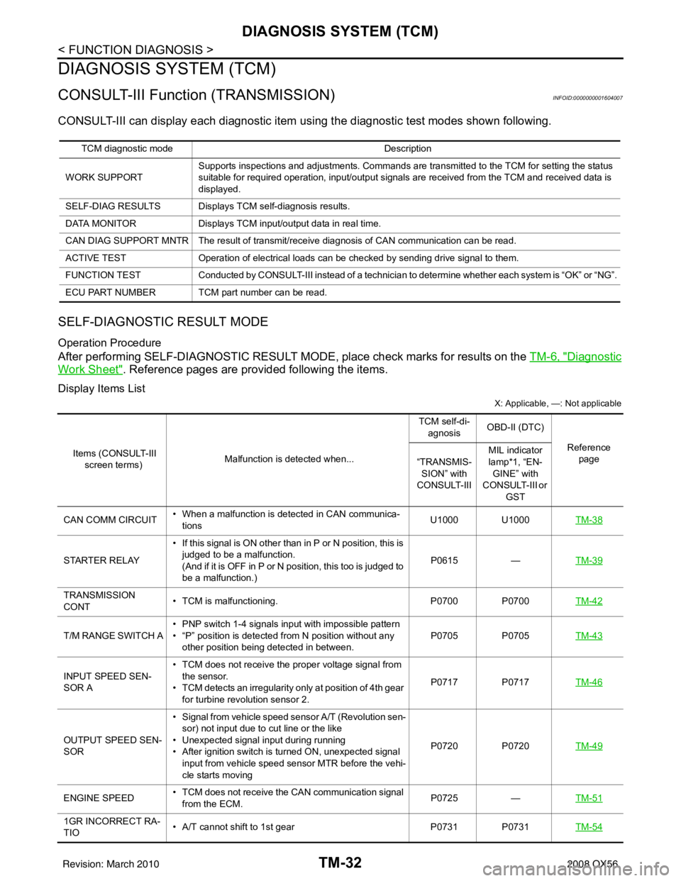
CONSULT-III can display each diagnostic item us ing the diagnostic test modes shown following.
SELF-DIAGNOSTIC RESULT MODE
Operation Procedure
After performing SELF-DIAGNOSTIC RESULT MO DE, place check marks for results on the TM-6, "Diagnostic
Work Sheet". Reference pages are provided following the items.
Display Items List
X: Applicable, —: Not applicable
TCM diagnostic mode Description
WORK SUPPORT Supports inspections and adjustments. Commands are transmitted to the TCM for setting the status
suitable for required operation, input/output signals are received from the TCM and received data is
displayed.
SELF-DIAG RESULTS Displays TCM self-diagnosis results.
DATA MONITOR Displays TCM input/output data in real time.
CAN DIAG SUPPORT MNTR The result of transmit/receive diagnosis of CAN communication can be read.
ACTIVE TEST Operation of electrical loads can be checked by sending drive signal to them.
FUNCTION TEST Conducted by CONSULT-III instead of a technici an to determine whether each system is “OK” or “NG”.
ECU PART NUMBER TCM part number can be read.
Items (CONSULT-III screen terms) Malfunction is detected when... TCM self-di-
agnosis OBD-II (DTC)
Reference page
“TRANSMIS-
SION” with
CONSULT-III MIL indicator
lamp*1, “EN-
GINE” with
CONSULT-III or GST
CAN COMM CIRCUIT • When a malfunction is detected in CAN communica-
tions U1000 U1000
TM-38
STARTER RELAY• If this signal is ON other than in P or N position, this is
judged to be a malfunction.
(And if it is OFF in P or N position, this too is judged to
be a malfunction.) P0615
—TM-39
TRANSMISSION
CONT • TCM is malfunctioning.
P0700 P0700TM-42
T/M RANGE SWITCH A• PNP switch 1-4 signals input with impossible pattern
• “P” position is detected from N position without any
other position being detected in between. P0705 P0705
TM-43
INPUT SPEED SEN-
SOR A• TCM does not receive the proper voltage signal from
the sensor.
• TCM detects an irregularity only at position of 4th gear
for turbine revolution sensor 2. P0717 P0717
TM-46
OUTPUT SPEED SEN-
SOR• Signal from vehicle speed sensor A/T (Revolution sen-
sor) not input due to cut line or the like
• Unexpected signal input during running
• After ignition switch is turned ON, unexpected signal
input from vehicle speed sensor MTR before the vehi-
cle starts moving P0720 P0720
TM-49
ENGINE SPEED• TCM does not receive the CAN communication signal
from the ECM. P0725
—TM-51
1GR INCORRECT RA-
TIO • A/T cannot shift to 1st gear
P0731 P0731TM-54
Revision: March 2010 2008 QX56
Page 3583 of 4083

TM-36
< FUNCTION DIAGNOSIS >
DIAGNOSIS SYSTEM (TCM)
ONOFF SOL MON (ON-OFF display) ——X LC/B solenoid
P POSI IND (ON-OFF display) —— X
R POSI IND (ON-OFF display) —— X
N POSI IND (ON-OFF display) —— X
D POSI IND (ON-OFF display) —— X
4TH POSI IND (ON-OFF display) —— X
3RD POSI IND (ON-OFF display) —— X
2ND POSI IND (ON-OFF display) —— X
1ST POSI IND (ON-OFF display) —— X
MANU MODE IND (ON-OFF display) — —X
Not mounted but displayed.
POWER M LAMP (ON-OFF display) —— X
F-SAFE IND/L (ON-OFF display) —— X
ATF WARN LAMP (ON-OFF display) — —X
BACK-UP LAMP (ON-OFF display) —— X
STARTER RELAY (ON-OFF display) — —X
RANGE SW3 MON (ON-OFF display) — —X
C/V CLB ID1 —— X
C/V CLB ID2 —— X
C/V CLB ID3 —— X
UNIT CLB ID1 —— X
UNIT CLB ID2 —— X
UNIT CLB ID3 —— X
TRGT GR RATIO —— X
TRGT PRES TCC (kPa) —— X
TRGT PRES L/P (kPa) —— X
TRGT PRES I/C (kPa) —— X
TRGT PRE FR/B (kPa) —— X
TRGT PRES D/C (kPa) —— X
TRG PRE HLR/C (kPa) —— X
SHIFT PATTERN —— X
DRV CST JUDGE —— X
START RLY MON —— X
NEXT GR POSI —— X
SHIFT MODE —— X
MANU GR POSI —— X
VEHICLE SPEED (km/h) —XX Vehicle speed recognized by the TCM.
Voltage (V) —— XDisplays the value measured by the voltage
probe.
Monitored item (Unit)
Monitor Item Selection
Remarks
ECU IN-
PUT SIG- NALS MAIN SIG-
NALS SELEC-
TION
FROM
MENU
Revision: March 2010 2008 QX56
Page 3586 of 4083

P0615 STARTER RELAYTM-39
< COMPONENT DIAGNOSIS >
CEF
G H
I
J
K L
M A
B
TM
N
O P
P0615 STARTER RELAY
DescriptionINFOID:0000000001604014
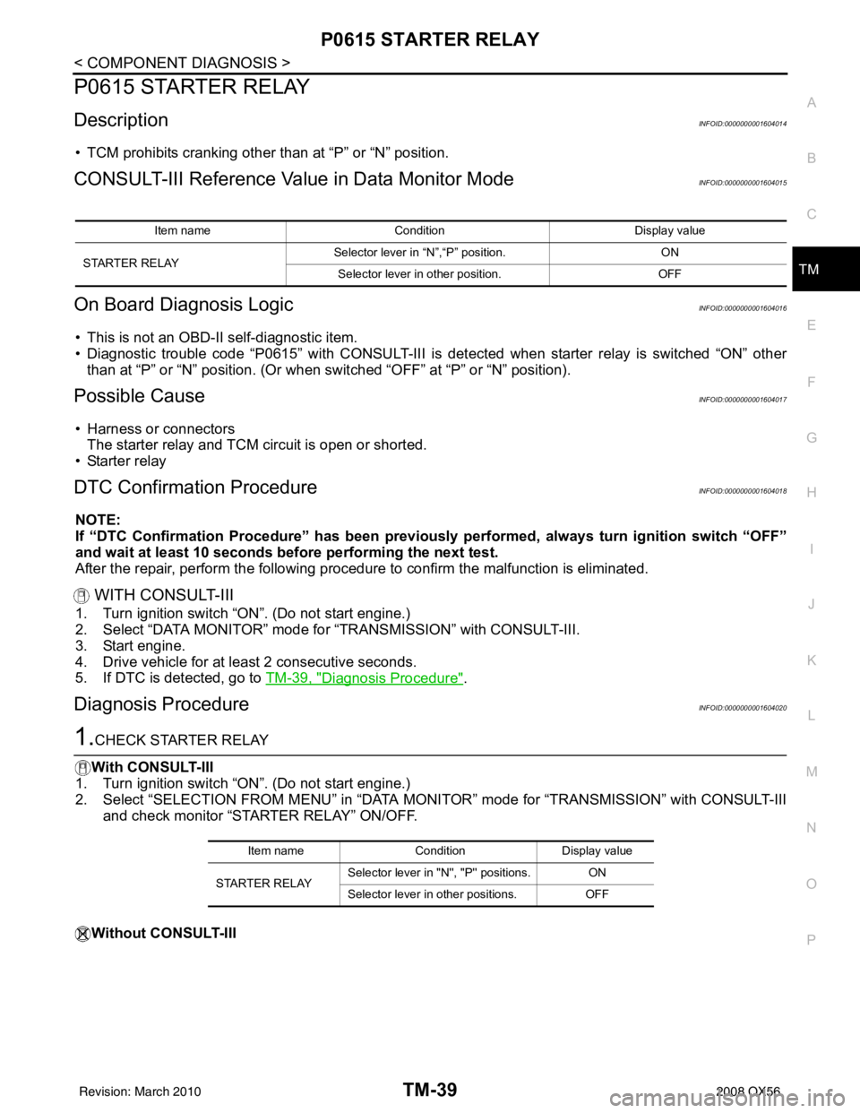
• TCM prohibits cranking other than at “P” or “N” position.
CONSULT-III Reference Val ue in Data Monitor ModeINFOID:0000000001604015
On Board Diagnosis LogicINFOID:0000000001604016
• This is not an OBD-II self-diagnostic item.
• Diagnostic trouble code “P0615” with CONSULT-III is det ected when starter relay is switched “ON” other
than at “P” or “N” position. (Or when s witched “OFF” at “P” or “N” position).
Possible CauseINFOID:0000000001604017
• Harness or connectors
The starter relay and TCM circuit is open or shorted.
•Starter relay
DTC Confirmation ProcedureINFOID:0000000001604018
NOTE:
If “DTC Confirmation Procedure” has been previously performed, always turn ignition switch “OFF”
and wait at least 10 seconds before performing the next test.
After the repair, perform the following procedure to confirm the malfunction is eliminated.
WITH CONSULT-III
1. Turn ignition switch “ON”. (Do not start engine.)
2. Select “DATA MONITOR” mode for “TRANSMISSION” with CONSULT-III.
3. Start engine.
4. Drive vehicle for at least 2 consecutive seconds.
5. If DTC is detected, go to TM-39, "
Diagnosis Procedure".
Diagnosis ProcedureINFOID:0000000001604020
1.CHECK STARTER RELAY
With CONSULT-III
1. Turn ignition switch “ON”. (Do not start engine.)
2. Select “SELECTION FROM MENU” in “DATA MONI TOR” mode for “TRANSMISSION” with CONSULT-III
and check monitor “STARTER RELAY” ON/OFF.
Without CONSULT-III
Item name Condition Display value
STARTER RELAY Selector lever in
“N”,“P” position. ON
Selector lever in other position. OFF
Item nameCondition Display value
STARTER RELAY Selector lever in "N
'', "P'' positions. ON
Selector lever in other positions. OFF
Revision: March 2010 2008 QX56
Page 3587 of 4083

TM-40
< COMPONENT DIAGNOSIS >
P0615 STARTER RELAY
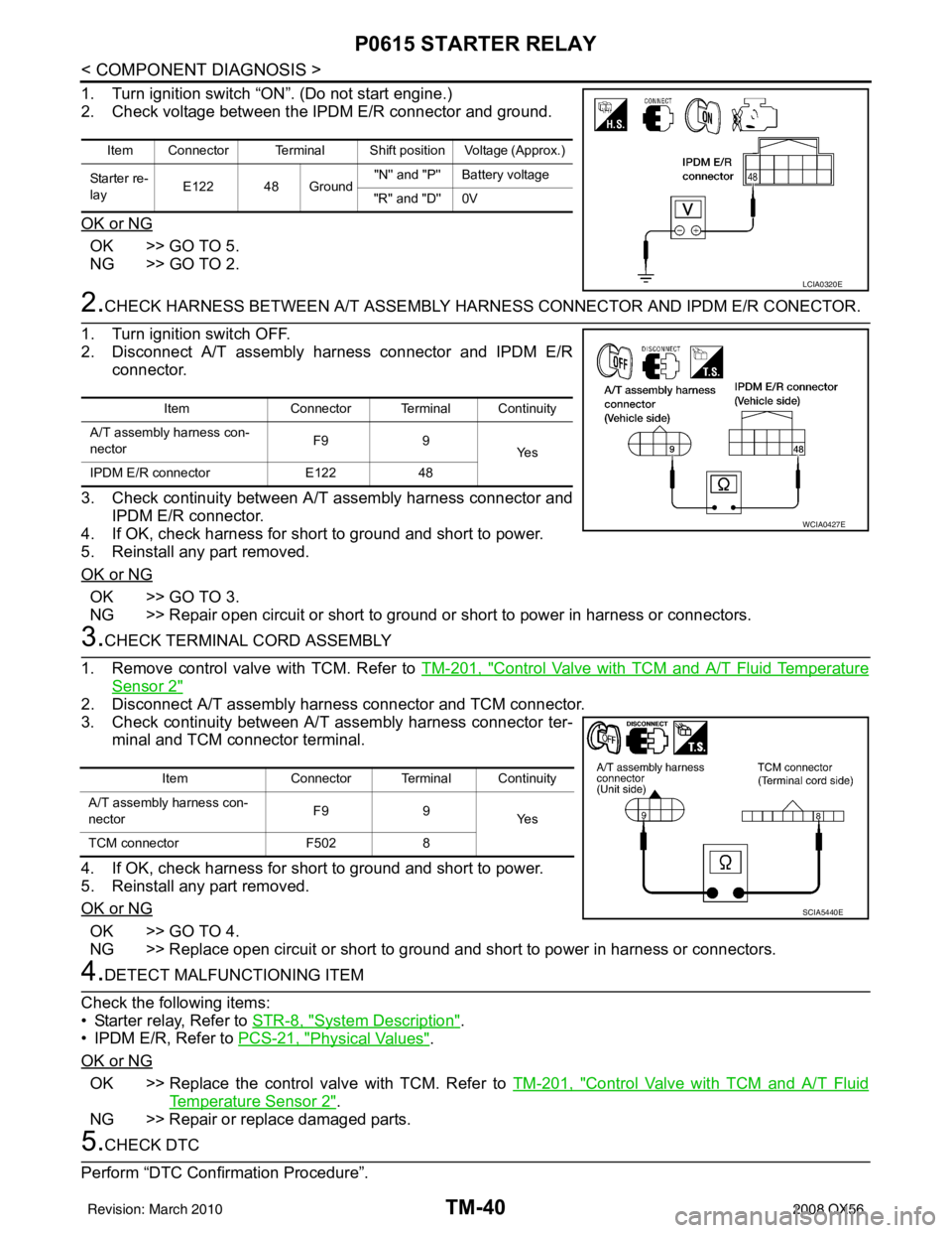
1. Turn ignition switch “ON”. (Do not start engine.)
2. Check voltage between the IPDM E/R connector and ground.
OK or NG
OK >> GO TO 5.
NG >> GO TO 2.
2.CHECK HARNESS BETWEEN A/T ASSEMBLY HARNESS CONNECTOR AND IPDM E/R CONECTOR.
1. Turn ignition switch OFF.
2. Disconnect A/T assembly harness connector and IPDM E/R connector.
3. Check continuity between A/T assembly harness connector and IPDM E/R connector.
4. If OK, check harness for short to ground and short to power.
5. Reinstall any part removed.
OK or NG
OK >> GO TO 3.
NG >> Repair open circuit or short to ground or short to power in harness or connectors.
3.CHECK TERMINAL CORD ASSEMBLY
1. Remove control valve with TCM. Refer to TM-201, "
Control Valve with TCM and A/T Fluid Temperature
Sensor 2"
2. Disconnect A/T assembly harness connector and TCM connector.
3. Check continuity between A/T assembly harness connector ter-
minal and TCM connector terminal.
4. If OK, check harness for short to ground and short to power.
5. Reinstall any part removed.
OK or NG
OK >> GO TO 4.
NG >> Replace open circuit or short to ground and short to power in harness or connectors.
4.DETECT MALFUNCTIONING ITEM
Check the following items:
• Starter relay, Refer to STR-8, "
System Description".
• IPDM E/R, Refer to PCS-21, "
Physical Values".
OK or NG
OK >> Replace the control valve with TCM. Refer to TM-201, "Control Valve with TCM and A/T Fluid
Temperature Sensor 2".
NG >> Repair or replace damaged parts.
5.CHECK DTC
Perform “DTC Confirmation Procedure”.
Item Connector Terminal Shift position Voltage (Approx.)
Starter re-
lay E122 48 Ground "N'' and "P'' Battery voltage
"R'' and "D'' 0V
LCIA0320E
Item Connector Terminal Continuity
A/T assembly harness con-
nector F9
9
Ye s
IPDM E/R connector E12248
WCIA0427E
Item Connector Terminal Continuity
A/T assembly harness con-
nector F9
9
Ye s
TCM connector F5028
SCIA5440E
Revision: March 2010 2008 QX56