2008 INFINITI QX56 ABS
[x] Cancel search: ABSPage 1654 of 4083
![INFINITI QX56 2008 Factory Service Manual P1574 ASCD VEHICLE SPEED SENSOREC-355
< COMPONENT DIAGNOSIS > [VK56DE]
C
D
E
F
G H
I
J
K L
M A
EC
NP
O
2.CHECK DTC WITH ABS ACTUATOR AND ELECTRIC UNIT (CONTROL UNIT)
Refer to BRC-24, "
CONSULT-III Fu INFINITI QX56 2008 Factory Service Manual P1574 ASCD VEHICLE SPEED SENSOREC-355
< COMPONENT DIAGNOSIS > [VK56DE]
C
D
E
F
G H
I
J
K L
M A
EC
NP
O
2.CHECK DTC WITH ABS ACTUATOR AND ELECTRIC UNIT (CONTROL UNIT)
Refer to BRC-24, "
CONSULT-III Fu](/manual-img/42/57030/w960_57030-1653.png)
P1574 ASCD VEHICLE SPEED SENSOREC-355
< COMPONENT DIAGNOSIS > [VK56DE]
C
D
E
F
G H
I
J
K L
M A
EC
NP
O
2.CHECK DTC WITH ABS ACTUATOR AND ELECTRIC UNIT (CONTROL UNIT)
Refer to BRC-24, "
CONSULT-III Function (ABS)".
OK or NG
OK >> GO TO 3.
NG >> Repair or replace.
3.CHECK COMBINATION METER FUNCTION
Check combination meter function.
Refer to MWI-5
.
>> INSPECTION END
Revision: March 2010 2008 QX56
Page 1715 of 4083
![INFINITI QX56 2008 Factory Service Manual EC-416
< COMPONENT DIAGNOSIS >[VK56DE]
ON BOARD REFUELING VAPOR RECOVERY (ORVR)
ON BOARD REFUELING VAPOR RECOVERY (ORVR)
System DescriptionINFOID:0000000001351317
From the beginning of refueling, the INFINITI QX56 2008 Factory Service Manual EC-416
< COMPONENT DIAGNOSIS >[VK56DE]
ON BOARD REFUELING VAPOR RECOVERY (ORVR)
ON BOARD REFUELING VAPOR RECOVERY (ORVR)
System DescriptionINFOID:0000000001351317
From the beginning of refueling, the](/manual-img/42/57030/w960_57030-1714.png)
EC-416
< COMPONENT DIAGNOSIS >[VK56DE]
ON BOARD REFUELING VAPOR RECOVERY (ORVR)
ON BOARD REFUELING VAPOR RECOVERY (ORVR)
System DescriptionINFOID:0000000001351317
From the beginning of refueling, the air and vapor insi
de the fuel tank go through refueling EVAP vapor cut
valve and EVAP/ORVR line to the EVAP canister. The vapor is absorbed by the EVAP canister and the air is
released to the atmosphere.
When the refueling has reached the full level of the fuel tank, the refueling EVAP vapor cut valve is closed and
refueling is stopped because of auto shut-off. The vapor which was absorbed by the EVAP canister is purged
during driving.
WARNING:
When conducting inspections below, be sure to observe the following:
• Put a “CAUTION: FLAMMABLE” sign in workshop.
• Do not smoke while servicing fuel system. Keep open flames and sparks away from work area.
• Be sure to furnish the workshop with a CO
2 fire extinguisher.
CAUTION:
• Before removing fuel line parts, carry out the following procedures:
- Put drained fuel in an explosion-pr oof container and put lid on securely.
- Release fuel pressure from fuel line. Refer to EC-494, "
Fuel Pressure Check" .
- Disconnect battery ground cable.
• Always replace O-ring when the fu el gauge retainer is removed.
• Do not kink or twist hose and tube when they are installed.
• Do not tighten hose and clamps excessively to avoid damaging hoses.
• After installation, run engine and check for fuel leaks at connection.
• Do not attempt to top off the fuel tank afte r the fuel pump nozzle shuts off automatically.
Continued refueling may cause fuel overflow, r esulting in fuel spray and possibly a fire.
Diagnosis ProcedureINFOID:0000000001351318
SYMPTOM: FUEL ODOR FROM EVAP CANISTER IS STRONG.
1.CHECK EVAP CANISTER
1. Remove EVAP canister with EVAP canister vent control valve and EVAP control system pressure sensor attached.
2. Weigh the EVAP canister with EVAP canister vent control valve and EVAP control system pressure sensor
attached.
The weight should be l ess than 2.5 kg (5.5 lb).
OK or NG
OK >> GO TO 2.
NG >> GO TO 3.
2.CHECK IF EVAP CANISTER SATURATED WITH WATER
PBIB1068E
Revision: March 2010 2008 QX56
Page 1766 of 4083
![INFINITI QX56 2008 Factory Service Manual ECM
EC-467
< ECU DIAGNOSIS > [VK56DE]
C
D
E
F
G H
I
J
K L
M A
EC
NP
O
Procedures for clearing the DTC and the 1st trip DT
C from the ECM memory are described in "HOW TO
ERASE EMISSION-RELATED DIAGNOST INFINITI QX56 2008 Factory Service Manual ECM
EC-467
< ECU DIAGNOSIS > [VK56DE]
C
D
E
F
G H
I
J
K L
M A
EC
NP
O
Procedures for clearing the DTC and the 1st trip DT
C from the ECM memory are described in "HOW TO
ERASE EMISSION-RELATED DIAGNOST](/manual-img/42/57030/w960_57030-1765.png)
ECM
EC-467
< ECU DIAGNOSIS > [VK56DE]
C
D
E
F
G H
I
J
K L
M A
EC
NP
O
Procedures for clearing the DTC and the 1st trip DT
C from the ECM memory are described in "HOW TO
ERASE EMISSION-RELATED DIAGNOSTIC INFORMATION".
For malfunctions in which 1st trip DTCs are displa yed, refer to "EMISSION-RELATED DIAGNOSTIC INFOR-
MATION ITEMS". These items are required by legal r egulations to continuously monitor the system/compo-
nent. In addition, the items monitored non-cont inuously are also displayed on CONSULT-III.
1st trip DTC is specified in Service $07 of SAE J1979. 1st trip DTC detection occurs without lighting up the MIL
and therefore does not warn the driver of a malfunction. However, 1st trip DTC detection will not prevent the
vehicle from being tested, for example during Inspection/Maintenance (I/M) tests.
When a 1st trip DTC is detected, check, print out or write down and erase (1st trip) DTC and Freeze Frame
data as specified in Work Flow procedure Step 2, refer to EC-8, "
Trouble Diagnosis Introduction". Then per-
form DTC Confirmation Procedure or Overall Function Che ck to try to duplicate the malfunction. If the mal-
function is duplicated, the item requires repair.
How to Read DTC and 1st Trip DTC
DTC and 1st trip DTC can be read by the following methods.
With CONSULT-III
With GST
CONSULT-III or GST (Generic Scan Tool ) Examples: P0340, P0850, P1148, etc.
These DTCs are prescribed by SAE J2012.
(CONSULT-III also displays the malfunctioning component or system.)
No Tools
The number of blinks of the MIL in the Diagnostic Test Mode II (Self-Diagnostic Results) indicates the DTC.
Example: 0340, 0850, 1148, etc.
These DTCs are controlled by NISSAN.
• 1st trip DTC No. is the same as DTC No.
• Output of a DTC indicates a malfunc tion. However, GST or the Diagnostic Test Mode II do not indi-
cate whether the malfunction is stil l occurring or has occurred in the past and has returned to nor-
mal. CONSULT-III can identify malfunction status as shown below. Therefore, using CONSULT-III (if
available) is recommended.
DTC or 1st trip DTC of a malfunction is display ed in SELF-DIAGNOSTIC RESULTS mode of CONSULT-III.
Time data indicates how many times the vehicle was driven after the last detection of a DTC.
If the DTC is being detected currently, the time data will be [0].
If a 1st trip DTC is stored in the ECM, the time data will be [1t].
FREEZE FRAME DATA AND 1ST TRIP FREEZE FRAME DATA
The ECM records the driving conditions such as fuel system status, calculated load value, engine coolant tem-
perature, short term fuel trim, long term fuel trim, engi ne speed, vehicle speed, absolute throttle position, base
fuel schedule and intake air temperature at the moment a malfunction is detected.
Data which are stored in the ECM memory, along with the 1st trip DTC, are called 1st trip freeze frame data.
The data, stored together with the DTC data, are ca lled freeze frame data and displayed on CONSULT-III or
GST. The 1st trip freeze frame dat a can only be displayed on the CONSULT-III screen, not on the GST. For
details, see EC-63, "
CONSULT-III Function (ENGINE)".
Only one set of freeze frame data (either 1st trip freez e frame data or freeze frame data) can be stored in the
ECM. 1st trip freeze frame data is stored in the ECM me mory along with the 1st trip DTC. There is no priority
for 1st trip freeze frame data and it is updated each time a different 1st trip DTC is detected. However, once
freeze frame data (2nd trip detection/MIL on) is stored in the ECM memory, 1st trip freeze frame data is no
longer stored. Remember, only one set of freeze frame data can be stored in the ECM. The ECM has the fol-
lowing priorities to update the data.
For example, the EGR malfunction (Priority: 2) was detected and the fr eeze frame data was stored in the 2nd
trip. After that when the misfire (Priority: 1) is detected in another trip, the freeze frame data will be updated
from the EGR malfunction to the misfire. The 1st trip freeze frame data is updated each time a different mal-
function is detected. There is no priority for 1st tr ip freeze frame data. However, once freeze frame data is
stored in the ECM memory, 1st trip freeze data is no longer stored (because only one freeze frame data or 1st
trip freeze frame data can be stored in the ECM). If freeze frame data is stored in the ECM memory and freeze
Priority Items
1 Freeze frame data Misfire — DTC: P0300 - P0308
Fuel Injection System Function — DTC: P0171, P0172, P0174, P0175
2 Except the above items (Includes A/T related items)
3 1st trip freeze frame data
Revision: March 2010 2008 QX56
Page 1781 of 4083
![INFINITI QX56 2008 Factory Service Manual EC-482
< SYMPTOM DIAGNOSIS >[VK56DE]
ENGINE CONTROL SYSTEM SYMPTOMS
1 - 6: The numbers refer to the order of inspection.
(continued on next page)
SYSTEM — ENGINE MECHANICAL & OTHER
Mass air flow sen INFINITI QX56 2008 Factory Service Manual EC-482
< SYMPTOM DIAGNOSIS >[VK56DE]
ENGINE CONTROL SYSTEM SYMPTOMS
1 - 6: The numbers refer to the order of inspection.
(continued on next page)
SYSTEM — ENGINE MECHANICAL & OTHER
Mass air flow sen](/manual-img/42/57030/w960_57030-1780.png)
EC-482
< SYMPTOM DIAGNOSIS >[VK56DE]
ENGINE CONTROL SYSTEM SYMPTOMS
1 - 6: The numbers refer to the order of inspection.
(continued on next page)
SYSTEM — ENGINE MECHANICAL & OTHER
Mass air flow sensor circuit
1
12 2
222 2 EC-106,
EC-113
Engine coolant temperature sensor circuit
333
EC-124,
EC-132
Air fuel ratio (A/F ) sensor 1 circuit EC-141
,
EC-145
,
EC-149
,
EC-153
,
EC-385
Throttle position sensor circuit
22EC-128
,
EC-194
,
EC-310
,
EC-312
,
EC-377
Accelerator pedal position sensor circuit 3 2 1EC-289
,
EC-370
,
EC-373
,
EC-381
Knock sensor circuit 23EC-204
Crankshaft position sensor (POS) circuit 2 2 EC-207
Camshaft position sensor (PHASE) circuit 3 2 EC-211
Vehicle speed signal circuit2 3 33EC-280
Power steering pressu re sensor circuit 23 3 EC-286
ECM 22333333333 EC-289,
EC-291
Intake valve timing control solenoid valve cir-
cuit 32 13223 3
EC-103
Park/Neutral position (PNP) signal circuit3 3 3 33EC-296
Refrigerant pressure sensor circuit 233 4 EC-423
Electrical load signal circuit 3EC-397
Air conditioner circuit 223333333 3 2 HAC-24
ABS actuator and electric unit (control unit) 4 BRC-37
SYMPTOM
Refer-
ence page
HARD/NO START/RESTART (EXCP. HA)
ENGINE STALL
HESITATION/SURGING/FLAT SPOT
SPARK KNOCK/DETONATION
LACK OF POWER/POOR ACCELERATION
HIGH IDLE/LOW IDLE
ROUGH IDLE/HUNTING
IDLING VIBRATION
SLOW/NO RETURN TO IDLE
OVERHEATS/WATER TEMPERATURE HIGH
EXCESSIVE FUEL CONSUMPTION
EXCESSIVE OIL CONSUMPTION
BATTERY DEAD (UNDER CHARGE)
Warranty symptom code AA AB AC AD AE AF AG AH AJ AK AL AM HA
Revision: March 2010 2008 QX56
Page 1874 of 4083

CYLINDER HEADEM-71
< ON-VEHICLE REPAIR >
C
DE
F
G H
I
J
K L
M A
EM
NP
O
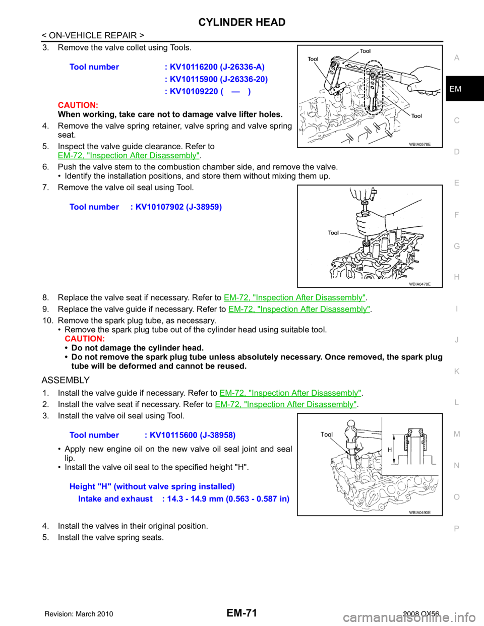
3. Remove the valve collet using Tools.
CAUTION:
When working, take care not to damage valve lifter holes.
4. Remove the valve spring retainer, valve spring and valve spring seat.
5. Inspect the valve guide clearance. Refer to EM-72, "
Inspection After Disassembly".
6. Push the valve stem to the combustion chamber side, and remove the valve. • Identify the installation positions, and store them without mixing them up.
7. Remove the valve oil seal using Tool.
8. Replace the valve seat if necessary. Refer to EM-72, "
Inspection After Disassembly".
9. Replace the valve guide if necessary. Refer to EM-72, "
Inspection After Disassembly".
10. Remove the spark plug tube, as necessary. • Remove the spark plug tube out of the cylinder head using suitable tool.
CAUTION:
• Do not damage the cylinder head.
• Do not remove the spark plug tube unless absolutely necessary. Once removed, the spark plug tube will be deformed and cannot be reused.
ASSEMBLY
1. Install the valve guide if necessary. Refer to EM-72, "Inspection After Disassembly".
2. Install the valve seat if necessary. Refer to EM-72, "
Inspection After Disassembly".
3. Install the valve oil seal using Tool.
• Apply new engine oil on the new valve oil seal joint and seallip.
• Install the valve oil seal to the specified height "H".
4. Install the valves in their original position.
5. Install the valve spring seats. Tool number
: KV10116200 (J-26336-A)
: KV10115900 (J-26336-20)
: KV10109220 ( — )
Tool number : KV10107902 (J-38959)
WBIA0578E
WBIA0478E
Tool number : KV10115600 (J-38958)
Height "H" (without valve spring installed) Intake and exhaust : 14.3 - 14.9 mm (0.563 - 0.587 in)
WBIA0490E
Revision: March 2010 2008 QX56
Page 2047 of 4083

LIGHTING & TURN SIGNAL SWITCHEXL-119
< REMOVAL AND INSTALLATION >
C
DE
F
G H
I
J
K
M A
B
EXL
N
O P
LIGHTING & TURN SIGNAL SWITCH
Removal and InstallationINFOID:0000000001547172
REMOVAL
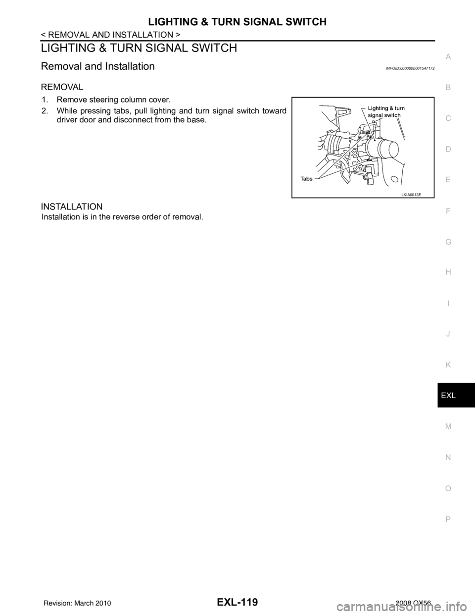
1. Remove steering column cover.
2. While pressing tabs, pull lighting and turn signal switch toward driver door and disconnect from the base.
INSTALLATION
Installation is in the reverse order of removal.
LKIA0013E
Revision: March 2010 2008 QX56
Page 2066 of 4083

FRONT BUMPEREXT-13
< SERVICE INFORMATION >
C
DE
F
G H
I
J
L
M A
B
EXT
N
O P
FRONT BUMPER
Removal and InstallationINFOID:0000000001609851
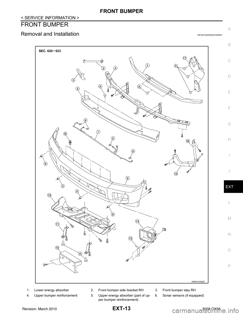
1. Lower energy absorber 2. Front bumper side bracket RH 3. Front bumper stay RH
4. Upper bumper reinforcement 5. Upper energy absorber (part of up- per bumper reinforcement) 6. Sonar sensors (if equipped)
AWKIA1559ZZ
Revision: March 2010
2008 QX56
Page 2067 of 4083

EXT-14
< SERVICE INFORMATION >
FRONT BUMPER
REMOVAL
1. Remove the side screws from the front fascia assembly.
2. Remove the screws from the front of fender protector. Refer to EXT-23
.
3. Remove the fog turn/fog lamp finisher and the fog turn/fog lamp. • Disconnect the harnesses.
4. Disconnect the sonar sensor, if equipped harness connector under the front fascia assembly.
5. Remove the fasteners, release the clips and remove the front fascia assembly.
6. Remove the plastic clips and remove the upper energy absorber.
7. Remove the upper bumper reinforcement.
8. Remove the plastic clips and remove the lower energy absorber.
9. Remove the front bumper stays and the front bumper side brackets, LH and RH.
10. Disconnect the sonar sensors, if equipped from the sonar sensor retainers, if equipped.
11. Remove the sonar sensors, if equipped and harness from the front fascia assembly. • Disconnect the sonar sensors, if equipped from the harness.
• Remove the sonar sensor retainers, if equipped from the front fascia assembly.
INSTALLATION
Installation is in the reverse order of removal.
7. Sonar sensor harness (if equipped) 8. Front fascia assembly 9. Sonar sensor retainers (if equipped)
10. Engine under cover 11. Front fascia bracket12. License plate bracket
13. Fog turn/fog lamp finisher LH/RH 14. Fog turn/fog lamp 15. Front bumper stay LH
16. Front bumper side bracket LH 17. Headlamp finisher (RH shown) A. Clip C103
B. Clip CS101
Revision: March 2010 2008 QX56