2008 INFINITI QX56 service indicator
[x] Cancel search: service indicatorPage 1568 of 4083
![INFINITI QX56 2008 Factory Service Manual P0456 EVAP CONTROL SYSTEMEC-269
< COMPONENT DIAGNOSIS > [VK56DE]
C
D
E
F
G H
I
J
K L
M A
EC
NP
O
5.INSTALL THE PRESSURE PUMP
To locate the EVAP leak, install EVAP service port adapter and pres-
sure p INFINITI QX56 2008 Factory Service Manual P0456 EVAP CONTROL SYSTEMEC-269
< COMPONENT DIAGNOSIS > [VK56DE]
C
D
E
F
G H
I
J
K L
M A
EC
NP
O
5.INSTALL THE PRESSURE PUMP
To locate the EVAP leak, install EVAP service port adapter and pres-
sure p](/manual-img/42/57030/w960_57030-1567.png)
P0456 EVAP CONTROL SYSTEMEC-269
< COMPONENT DIAGNOSIS > [VK56DE]
C
D
E
F
G H
I
J
K L
M A
EC
NP
O
5.INSTALL THE PRESSURE PUMP
To locate the EVAP leak, install EVAP service port adapter and pres-
sure pump to EVAP service port securely.
NOTE:
Improper installation of the EV AP service port adapter to the
EVAP service port may cause leaking.
With CONSULT-III>>GO TO 6.
Without CONSULT-III>>GO TO 7.
6.CHECK FOR EVAP LEAK
With CONSULT-III
1. Turn ignition switch ON.
2. Select “EVAP SYSTEM CLOSE” of “WORK SUPPORT” mode with CONSULT-III.
3. Touch “START” and apply pressure into the EVAP line until the pressure indicator reaches the middle of the bar graph.
CAUTION:
• Do not use compressed air or a high pressure pump.
• Do not exceed 4.12 kPa (0.042 kg/cm
2 , 0.6 psi) of pressure in the system.
4. Using EVAP leak detector, locate the EVAP leak. For the leak detector, refer to the instruction manual for more details.
Refer to EC-37, "
Description" .
OK or NG
OK >> GO TO 8.
NG >> Repair or replace.
7.CHECK FOR EVAP LEAK
Without CONSULT-III
1. Turn ignition switch OFF.
BBIA0366E
SEF916U
SEF200U
Revision: March 2010 2008 QX56
Page 1795 of 4083
![INFINITI QX56 2008 Factory Service Manual EC-496
< ON-VEHICLE MAINTENANCE >[VK56DE]
EVAP LEAK CHECK
EVAP LEAK CHECK
How to Detect Fuel Vapor LeakageINFOID:0000000001351309
CAUTION:
• Never use compressed air or a high pressure pump.
• Do INFINITI QX56 2008 Factory Service Manual EC-496
< ON-VEHICLE MAINTENANCE >[VK56DE]
EVAP LEAK CHECK
EVAP LEAK CHECK
How to Detect Fuel Vapor LeakageINFOID:0000000001351309
CAUTION:
• Never use compressed air or a high pressure pump.
• Do](/manual-img/42/57030/w960_57030-1794.png)
EC-496
< ON-VEHICLE MAINTENANCE >[VK56DE]
EVAP LEAK CHECK
EVAP LEAK CHECK
How to Detect Fuel Vapor LeakageINFOID:0000000001351309
CAUTION:
• Never use compressed air or a high pressure pump.
• Do not exceed 4.12 kPa (0.042 kg/cm
2, 0.6 psi) of pressure in EVAP system.
NOTE:
• Do not start engine.
• Improper installation of EVAP service port adapter to the EVAP service port may cause a leak.
WITH CONSULT-IIl
1. Attach the EVAP service port adapter securely to the EVAP service port.
2. Also attach the pressure pump and hose to the EVAP service port adapter.
3. Turn ignition switch ON.
4. Select the “EVAP SYSTEM CLOSE” of “WORK SUPPORT MODE” with CONSULT-IIl.
5. Touch “START”. A bar graph (Pressure indicating display) will appear on the screen.
6. Apply positive pressure to the EVAP system until t he pressure indicator reaches the middle of the bar
graph.
7. Remove EVAP service port adapter and hose with pressure pump.
8. Locate the leak using a leak detector. Refer to EC-37, "
Descrip-
tion".
WITHOUT CONSULT-IIl
1. Attach the EVAP service port adapter securely to the EVAP ser- vice port.
2. Also attach the pressure pump with pressure gauge to the EVAP service port adapter.
SEF200U
BBIA0366E
SEF462UA
Revision: March 2010 2008 QX56
Page 1912 of 4083

SERVICE DATA AND SPECIFICATIONS (SDS)EM-109
< SERVICE DATA AND SPECIFICATIONS (SDS)
C
DE
F
G H
I
J
K L
M A
EM
NP
O
Unit: mm (in)
SPARK PLUG
Unit: mm (in)
*: Always check with the Parts Department for the latest parts information.
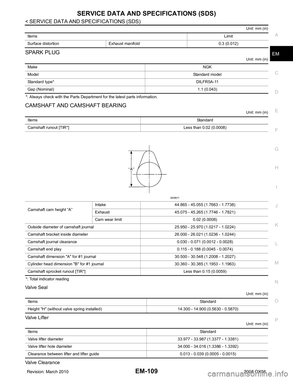
CAMSHAFT AND CAMSHAFT BEARING
Unit: mm (in)
*: Total indicator reading
Valve Seal
Unit: mm (in)
Valve Lifter
Unit: mm (in)
Valve Clearance
Items
Limit
Surface distortion Exhaust manifold 0.3 (0.012)
Make NGK
Model Standard model
Standard type* DILFR5A-11
Gap (Nominal) 1.1 (0.043)
ItemsStandard
Camshaft runout [TIR*] Less than 0.02 (0.0008)
Camshaft cam height “A” Intake
44.865 - 45.055 (1.7663 - 1.7738)
Exhaust 45.075 - 45.265 (1.7746 - 1.7821)
Cam wear limit 0.02 (0.0008)
Outside diameter of camshaft journal 25.950 - 25.970 (1.0217 - 1.0224)
Camshaft bracket inside diameter 26.000 - 26.021 (1.0236 - 1.0244)
Camshaft journal clearance 0.030 - 0.071 (0.0012 - 0.0028)
Camshaft end play 0.115 - 0.188 (0.0045 - 0.0074)
Camshaft dimension "A" for #1 journal 30.500 - 30.548 (1.2008 - 1.2027)
Cylinder head dimension "B" for #1 journal 30.360 - 30.385 (1.1953 - 1.1963)
Camshaft sprocket runout [TIR*] Less than 0.15 (0.0059)
SEM671
Items Standard
Height "H" (without valve spring installed) 14.300 - 14.900 (0.5630 - 0.5870)
Items Standard
Valve lifter diameter 33.977 - 33.987 (1.3377 - 1.3381)
Valve lifter hole diameter 34.000 - 34.016 (1.3386 - 1.3392)
Clearance between lifter and lifter guide 0.013 - 0.039 (0.0005 - 0.0015)
Revision: March 2010 2008 QX56
Page 1919 of 4083

EM-116
< SERVICE DATA AND SPECIFICATIONS (SDS)
SERVICE DATA AND SPECIFICATIONS (SDS)
*: Total indicator reading
MAIN BEARING
Unit: mm (in)
Main journal dia. “Dm” grade (No. 2, 3 and 4)StandardGrade No. A
Grade No. B
Grade No. C
Grade No. D
Grade No. E
Grade No. F
Grade No. G
Grade No. H
Grade No. J
Grade No. K
Grade No. L
Grade No. M
Grade No. N
Grade No. P
Grade No. R
Grade No. S
Grade No. T
Grade No. U
Grade No. V
Grade No. W
Grade No. X
Grade No. Y
Grade No. 1
Grade No. 2 63.963 - 63.964 (2.5182 - 2.5183)
63.962 - 63.963 (2.5182 - 2.5182)
63.961 - 63.962 (2.5181 - 2.5182)
63.960 - 63.961 (2.5181 - 2.5181)
63.959 - 63.960 (2.5181 - 2.5181)
63.958 - 63.959 (2.5180 - 2.5181)
63.957 - 63.958 (2.5180 - 2.5180)
63.956 - 63.957 (2.5179 - 2.5180)
63.955 - 63.956 (2.5179 - 2.5179)
63.954 - 63.955 (2.5179 - 2.5179)
63.953 - 63.954 (2.5178 - 2.5179)
63.952 - 63.953 (2.5178 - 2.5178)
63.951 - 63.952 (2.5178 - 2.5178)
63.950 - 63.951 (2.5177 - 2.5178)
63.949 - 63.950 (2.5177 - 2.5177)
63.948 - 63.949 (2.5176 - 2.5177)
63.947 - 63.948 (2.5176 - 2.5176)
63.946 - 63.947 (2.5176 - 2.5176)
63.945 - 63.946 (2.5175 - 2.5176)
63.944 - 63.945 (2.5175 - 2.5175)
63.943 - 63.944 (2.5174 - 2.5175)
63.942 - 63.943 (2.5174 - 2.5174)
63.941 - 63.942 (2.5174 - 2.5174)
63.940 - 63.941 (2.5173 - 2.5174)
Pin journal dia. “Dp” StandardGrade No. 0 53.968 - 53.974 (2.1247 - 2.1250)
Grade No. 1 53.962 - 53.968 (2.1245 - 2.1247)
Grade No. 2 53.956 - 53.962 (2.1243 - 2.1245)
Center distance “r” 45.96 - 46.04 (1.8094 - 1.8126)
Out-of-round (Difference between X and Y) Limit0.002 (0.0001)
Taper (Difference between A and B) 0.002 (0.0001)
Runout [TIR*] Less than 0.05 (0.002)
Crankshaft end play Standard
0.10 - 0.26 (0.0039 - 0.0102)
Limit 0.30 (0.0118)
Grade number* UPR/LWR Thickness Identification color Remarks
PBIC0189E
Revision: March 2010 2008 QX56
Page 2125 of 4083

FSU-8
< ON-VEHICLE MAINTENANCE >
ON-VEHICLE SERVICE
• Your alignment machine should be regularly calibrated in order to give correct information.
• Check with the manufacturer of your specific alignment machine for their recommended Service/Cali-
bration Schedule.
THE ALIGNMENT PROCESS
IMPORTANT: Use only the alignment specifications listed in this Service Manual. Refer to FSU-25,
"Wheelarch Height (Unladen*1)" .
1. When displaying the alignment settings, many alignment machines use “indicators”: (Green/red, plus or minus, Go/No Go). Do NOT use these indicators.
• The alignment specifications programmed into your alignment machine that operate these indicators may not be correct.
• This may result in an ERROR.
2. Some newer alignment machines are equipped with an optional “Rolling Compensation” method to “com- pensate” the sensors (alignment targets or head units). Do NOT use this “Rolling Compensation”
method.
• Use the “Jacking Compensation” method. After inst alling the alignment targets or head units, raise the
vehicle and rotate the wheels 1/2 turn both ways.
• See Instructions in the alignment machine you are using for more information.
CAMBER AND CASTER
1. Measure camber and caster of both the right and left wheels
with a suitable alignment gauge and adjust as necessary to
specification.
NOTE:
Some vehicles may be equipped with straight (non-adjustable)
lower link bolts and washers. In order to adjust camber and
caster on these vehicles, first replace the lower link bolts and
washers with adjustable (cam) bolts and washers.
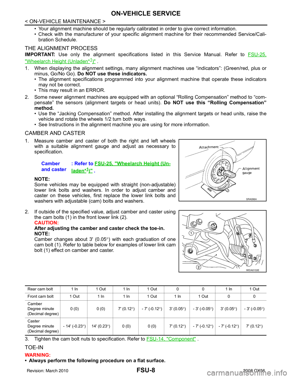
2. If outside of the specified value, adjust camber and caster using the cam bolts (1) in the front lower link (2).
CAUTION:
After adjusting the camber and caster check the toe-in.
NOTE:
Camber changes about 3' (0.05 °) with each graduation of one
cam bolt (1). Refer to table below for examples of lower link cam
bolt (1) effect on camber and caster.
3. Tighten the cam bolt nuts to specification. Refer to FSU-14, "
Component" .
TOE-IN
WARNING:
• Always perform the following procedure on a flat surface.
Camber
and caster
: Refer to
FSU-25, "
Wheelarch Height (Un-
laden*1)" .
SRA096A
WEIA0153E
Rear cam bolt 1 In 1 Out 1 In 1 Out 0 01 In 1 Out
Front cam bolt 1 Out 1 In 1 In 1 Out 1 In 1 Out 0 0
Camber
Degree minute
(Decimal degree) 0 (0) 0 (0) 7' (0.12
°) - 7' (-0.12 °)3' (0.05 °) - 3' (-0.05 °)3' (0.05 °) - 3' (-0.05 °)
Caster
Degree minute
(Decimal degree) - 14' (-0.23
°) 14' (0.23 °) 0 (0) 0 (0) 7' (0.12 °) - 7' (-0.12 °) - 7' (-0.12 °)7' (0.12 °)
Revision: March 2010 2008 QX56
Page 2160 of 4083

GI-18
< HOW TO USE THIS MANUAL >
TERMINOLOGY
Nonvolatile random access memory NVRAM***
On board diagnostic system OBD system Self-diagnosis
Open loop OL Open loop
Oxidation catalyst OC Catalyst
Oxidation catalytic converter system OC system ***
Oxygen sensor O2S Exhaust gas sensor
Park position switch *** Park switch
Transmission range switch *** Park/neutral switch
Inhibitor switch
Neutral position switch
Periodic trap oxidizer system PTOX system ***
Positive crankcase ventilation PCV Positive crankcase ventilation
Positive crankcase ventilation valve PCV valve PCV valve
Powertrain cont rol module PCM ***
Programmable read only memory PROM ***
Pulsed secondary air injection control sole-
noid valve PAIRC solenoid valve
AIV control solenoid valve
Pulsed secondary air injection system PAIR system Air induction valve (AIV) control
Pulsed secondary air injection valve PAIR valve Air induction valve
Random access memory RAM ***
Read only memory ROM ***
Scan tool ST ***
Secondary air injection pump AIR pump***
Secondary air injection system AIR system ***
Sequential multiport fuel injection system SFI system Sequential fuel injection
Service reminder indicator SRI***
Simultaneous multiport fuel injection sys-
tem ***
Simultaneous fuel injection
Smoke puff limiter system SPL system ***
Supercharger SC ***
Supercharger bypass SCB ***
System readiness test SRT ***
Thermal vacuum valve TVVThermal vacuum valve
Three way catalyst TWCCatalyst
Three way catalytic converter system TWC system ***
Three way + oxidation catalyst TWC + OCCatalyst
Three way + oxidation catalytic converter
system TWC + OC system
***
Throttle body TB Throttle chamber
SPI body
Throttle body fuel injection system TBI system Fuel injection control
Throttle position TP Throttle position
Throttle position sensor TPS Throttle sensor
Throttle position switch TP switch Throttle switch
Torque converter clutch solenoid valve TCC solenoid valve Lock-up cancel solenoid
Lock-up solenoid
NEW TERM
NEW ACRONYM /
ABBREVIATION OLD TERM
Revision: March 2010
2008 QX56
Page 2278 of 4083
![INFINITI QX56 2008 Factory Service Manual MODE DOOR MOTORHAC-25
< COMPONENT DIAGNOSIS > [AUTOMATIC AIR CONDITIONER]
C
D
E
F
G H
J
K L
M A
B
HAC
N
O P
The mode door motor (front) is attached to the heater & cooling unit
assembly. It rotates so INFINITI QX56 2008 Factory Service Manual MODE DOOR MOTORHAC-25
< COMPONENT DIAGNOSIS > [AUTOMATIC AIR CONDITIONER]
C
D
E
F
G H
J
K L
M A
B
HAC
N
O P
The mode door motor (front) is attached to the heater & cooling unit
assembly. It rotates so](/manual-img/42/57030/w960_57030-2277.png)
MODE DOOR MOTORHAC-25
< COMPONENT DIAGNOSIS > [AUTOMATIC AIR CONDITIONER]
C
D
E
F
G H
J
K L
M A
B
HAC
N
O P
The mode door motor (front) is attached to the heater & cooling unit
assembly. It rotates so that air is discharged from the outlet as indi-
cated by the A/C auto amp. Motor rotation is conveyed to a link
which activates the mode door.
Mode Door Motor (Front) Component Function CheckINFOID:0000000001679783
INSPECTION FLOW
1.CONFIRM SYMPTOM BY PERFORMING O PERATIONAL CHECK - DISCHARGE AIR
1. Press mode switch four times and then press the (DEF) switch. Each position indicator should change shape (on display).
2. Confirm that discharge air comes out accordi ng to the air distribution table. Refer to HAC-15, "
Discharge
Air Flow (Front)".
NOTE:
Confirm that the compressor clutch is engaged (visual inspection) and intake door position is at FRESH
when DEF ( ) or D/F ( ) is selected.
Can a symptom be duplicated?
YES >> GO TO 3.
NO >> GO TO 2.
2.PERFORM COMPLETE OPERATIONAL CHECK
Perform a complete operational check and check for any symptoms. Refer to HAC-4, "
Operational Check
(Front)".
Can a symptom be duplicated?
YES >> Refer to HAC-3, "How to Perform Trouble Diagnosis For Quick And Accurate Repair".
NO >> System OK.
3.CHECK FOR SERVICE BULLETINS
Check for any service bulletins.
>> GO TO 4.
4.CHECK MODE DOOR OPERATION
Check and verify mode door mechanism for smooth operation in each mode.
Is the inspection result normal?
YES >> GO TO 5.
NO >> Repair as necessary.
5.PERFORM A/C AUTO AMP. SELF-DIAGNOSIS
Perform self-diagnosis to check for any codes. Refer to HAC-22, "
A/C Auto Amp. Self-Diagnosis".
Are any self-diagnosis codes present?
YES >> Refer to HAC-23, "A/C System Self-Diagnosis Code Chart".
NO >> GO TO 6.
6.PERFORM A/C AND AV SWITCH ASSEMBLY SELF-DIAGNOSIS
Perform self-diagnosis to check the A/C and AV switch assembly. Refer to HAC-22, "
A/C and AV Switch
Assembly Self-Diagnosis".
Is the inspection result normal?
YES >> Replace A/C and AV switch assembly. Refer to VTL-7, "Removal and Installation".
NO >> GO TO 7.
WJIA0587E
Revision: March 2010 2008 QX56
Page 2294 of 4083
![INFINITI QX56 2008 Factory Service Manual INTAKE DOOR MOTORHAC-41
< COMPONENT DIAGNOSIS > [AUTOMATIC AIR CONDITIONER]
C
D
E
F
G H
J
K L
M A
B
HAC
N
O P
COMPONENT DESCRIPTION
Intake door motor
The intake door motor is attached to the intake un INFINITI QX56 2008 Factory Service Manual INTAKE DOOR MOTORHAC-41
< COMPONENT DIAGNOSIS > [AUTOMATIC AIR CONDITIONER]
C
D
E
F
G H
J
K L
M A
B
HAC
N
O P
COMPONENT DESCRIPTION
Intake door motor
The intake door motor is attached to the intake un](/manual-img/42/57030/w960_57030-2293.png)
INTAKE DOOR MOTORHAC-41
< COMPONENT DIAGNOSIS > [AUTOMATIC AIR CONDITIONER]
C
D
E
F
G H
J
K L
M A
B
HAC
N
O P
COMPONENT DESCRIPTION
Intake door motor
The intake door motor is attached to the intake unit. It rotates so that
air is drawn from inlets set by the A/C auto amp. Motor rotation is
conveyed to a lever which activates the intake door.
Intake Door Motor Component Function CheckINFOID:0000000001679790
INSPECTION FLOW
1.CONFIRM SYMPTOM BY PERFORMING OPERATIONAL CHECK - REC ( )
1. Press the mode switch to vent mode( ).
2. Press REC ( ) switch. The REC ( )indicator should illuminate.
3. Press REC ( ) switch again. The REC ( ) indicator should go out.
4. Listen for intake door position change (you should hear blower sound change slightly).
Can a symptom be duplicated?
YES >> GO TO 3.
NO >> GO TO 2.
2.PERFORM COMPLETE OPERATIONAL CHECK
Perform a complete operational check and check for any symptoms. Refer to HAC-4, "
Operational Check
(Front)".
Can a symptom be duplicated?
YES >> Refer to HAC-3, "How to Perform Trouble Diagnosis For Quick And Accurate Repair".
NO >> System OK.
3.CHECK FOR SERVICE BULLETINS
Check for any service bulletins.
>> GO TO 4.
4.CHECK INTAKE DOOR OPERATION
Check and verify intake door me chanism for smooth operation.
Is the inspection result normal?
YES >> GO TO 5.
NO >> Repair intake door mechanism.
5.PERFORM SELF-DIAGNOSIS
Perform self-diagnosis to check for any codes. Refer to HAC-22, "
A/C and AV Switch Assembly Self-Diagno-
sis".
Are any self-diagnosis codes present?
YES >> Refer to HAC-23, "A/C System Self-Diagnosis Code Chart".
NO >> GO TO 6.
6.RECHECK FOR ANY SYMPTOMS
Perform a complete operational check for any symptoms. Refer to HAC-4, "
Operational Check (Front)".
Does another symptom exist?
YES >> Refer to HAC-3, "How to Perform Trouble Diagnosis For Quick And Accurate Repair".
NO >> Replace A/C auto amp. Refer to VTL-7, "
Removal and Installation".
WJIA0552E
Revision: March 2010 2008 QX56