2008 INFINITI QX56 oil filter
[x] Cancel search: oil filterPage 1190 of 4083
![INFINITI QX56 2008 Factory Service Manual DLN-160
< DISASSEMBLY AND ASSEMBLY >[ATX14B]
TRANSFER ASSEMBLY
• Check each control valve spring for damage or distortion. Also
check its free length, outer diameter and wire diameter. If any dam-
a INFINITI QX56 2008 Factory Service Manual DLN-160
< DISASSEMBLY AND ASSEMBLY >[ATX14B]
TRANSFER ASSEMBLY
• Check each control valve spring for damage or distortion. Also
check its free length, outer diameter and wire diameter. If any dam-
a](/manual-img/42/57030/w960_57030-1189.png)
DLN-160
< DISASSEMBLY AND ASSEMBLY >[ATX14B]
TRANSFER ASSEMBLY
• Check each control valve spring for damage or distortion. Also
check its free length, outer diameter and wire diameter. If any dam-
age or fatigue is found, replace the control valve body with a new
one. Refer to DLN-140, "
Disassembly and Assembly".
CAUTION:
Replace control valve body togeth er with clutch return spring
as a set.
Clutch
• Check the drive plate facings and driven plate for damage, cracks or other abnormality. If any abnormalities are found, replace with a
new one.
• Check the thickness of the drive plate facings and driven plate.
Refer to DLN-140, "
Disassembly and Assembly".
CAUTION:
• Measure facing thickness at 3 points to take an average.
• Check all drive and driven plates.
• Check return spring for damage or deformation.
• Do not remove spring from plate.
Return Spring
• Check the stamped mark shown. T hen, check that the free lengths,
(include thickness of plate) are within specifications. If any abnor-
mality is found, replace with a new return spring assembly of the
same stamped number. Refer to DLN-140, "
Disassembly and
Assembly".
ASSEMBLY
Center Case
1. Apply ATF to the new O-ring, and install it on the oil filter stud.
CAUTION:
Do not reuse O-rings.
2. Install the oil filter stud to the oil filter.
SMT948C
SMT949C
SDIA2176E
SDIA3180E
Revision: March 2010 2008 QX56
Page 1191 of 4083
![INFINITI QX56 2008 Factory Service Manual TRANSFER ASSEMBLYDLN-161
< DISASSEMBLY AND ASSEMBLY > [ATX14B]
C
EF
G H
I
J
K L
M A
B
DLN
N
O P
3. Apply ATF to the two new O-rings (1), and install them on the oil filter (2).
CAUTION:
Do not reuse O INFINITI QX56 2008 Factory Service Manual TRANSFER ASSEMBLYDLN-161
< DISASSEMBLY AND ASSEMBLY > [ATX14B]
C
EF
G H
I
J
K L
M A
B
DLN
N
O P
3. Apply ATF to the two new O-rings (1), and install them on the oil filter (2).
CAUTION:
Do not reuse O](/manual-img/42/57030/w960_57030-1190.png)
TRANSFER ASSEMBLYDLN-161
< DISASSEMBLY AND ASSEMBLY > [ATX14B]
C
EF
G H
I
J
K L
M A
B
DLN
N
O P
3. Apply ATF to the two new O-rings (1), and install them on the oil filter (2).
CAUTION:
Do not reuse O-rings.
4. Install the oil filter to the center case. Tighten the bolts to the specified torque. Refer to DLN-125, "
Removal and Installation".
CAUTION:
• Do not damage oil filter.
• Attach oil filter and tighten bolts evenly.
5. Install the outer gear and inner gear into the sub oil pump hous- ing, and measure the side clearance. Refer to " DLN-140, "
Dis-
assembly and Assembly".
6. Align the dowel pin hole and bolt hole of the sub oil pump assembly with the center case. Install the sub oil pump cover.
Then tighten to the specified torque. Refer to DLN-140, "
Disas-
sembly and Assembly"
7. Apply ATF to the new O-ring and install it to the transfer motor.CAUTION:
Do not reuse O-rings.
8. Fit the double-flat end of the transfer motor shaft into the slot of the sub-oil pump assembly. Then tighten to the specified torque.
Refer to DLN-140, "
Disassembly and Assembly"
CAUTION:
Be sure to install connector bracket.
WDIA0285E
SDIA2136E
SDIA2135E
SDIA2328E
SDIA2787E
Revision: March 2010 2008 QX56
Page 1377 of 4083
![INFINITI QX56 2008 Factory Service Manual EC-78
< COMPONENT DIAGNOSIS >[VK56DE]
TROUBLE DIAGNOSIS - SPECIFICATION VALUE
Check “A/F ALPHA-B1”, “A/F ALPHA-B2” for approximat
ely 1 minute because they may fluctuate. It is NG
if the indic INFINITI QX56 2008 Factory Service Manual EC-78
< COMPONENT DIAGNOSIS >[VK56DE]
TROUBLE DIAGNOSIS - SPECIFICATION VALUE
Check “A/F ALPHA-B1”, “A/F ALPHA-B2” for approximat
ely 1 minute because they may fluctuate. It is NG
if the indic](/manual-img/42/57030/w960_57030-1376.png)
EC-78
< COMPONENT DIAGNOSIS >[VK56DE]
TROUBLE DIAGNOSIS - SPECIFICATION VALUE
Check “A/F ALPHA-B1”, “A/F ALPHA-B2” for approximat
ely 1 minute because they may fluctuate. It is NG
if the indication is out of the SP value even a little.
OK or NG
OK >> GO TO 17.
NG (Less than the SP value)>>GO TO 2.
NG (More than the SP value)>>GO TO 3.
2.CHECK “B/FUEL SCHDL”
Select “B/FUEL SCHDL” in “SPEC” of “DATA MONITOR” mode, and make sure that the indication is within the
SP value.
OK or NG
OK >> GO TO 4.
NG (More than the SP value)>>GO TO 19.
3.CHECK “B/FUEL SCHDL”
Select “B/FUEL SCHDL” in “SPEC” of “DATA MONITOR” mode, and make sure that the indication is within the
SP value.
OK or NG
OK >> GO TO 6.
NG (More than the SP value)>>GO TO 6.
NG (Less than the SP value)>>GO TO 25.
4.CHECK “A/F ALPHA-B1”, “A/F ALPHA-B2”
1. Stop the engine.
2. Disconnect PCV hose, and then plug it.
3. Start engine.
4. Select “A/F ALPHA-B1”, “A/F AL PHA-B2” in “SPEC” of “DATA MONITOR” mode, and make sure that the
each indication is within the SP value.
OK or NG
OK >> GO TO 5.
NG >> GO TO 6.
5.CHANGE ENGINE OIL
1. Stop the engine.
2. Change engine oil. NOTE:
This symptom may occur when a large amount of gasoline is mixed with engine oil because of driving
conditions (such as when engine oil temperature does not rise enough since a journey distance is too
short during winter). The symptom will not be detected after changing engine oil or changing driving con-
dition.
>>INSPECTION END
6.CHECK FUEL PRESSURE
Check fuel pressure. (Refer to EC-494, "
Fuel Pressure Check" .)
OK or NG
OK >> GO TO 9.
NG (Fuel pressure is too high)>>Replace fuel pressure regulator, refer to EC-494, "
Fuel Pressure Check" .
GO TO 8.
NG (Fuel pressure is too low)>>GO TO 7.
7.DETECT MALFUNCTIONING PART
1. Check the following.
- Clogged and bent fuel hose and fuel tube
- Clogged fuel filter
- Fuel pump and its circuit (Refer to EC-494, "
Fuel Pressure Check" .)
2. If NG, repair or replace the malfunctioning part. (Refer to EC-494, "
Fuel Pressure Check" .)
If OK, replace fuel pressure regulator.
Revision: March 2010 2008 QX56
Page 1783 of 4083
![INFINITI QX56 2008 Factory Service Manual EC-484
< SYMPTOM DIAGNOSIS >[VK56DE]
ENGINE CONTROL SYSTEM SYMPTOMS
1 - 6: The numbers refer to the order of inspection.Exhaust Exhaust manifold/Tube/Muffler/
Gasket 55555 55 5EM-30
,
EX-
5Three way INFINITI QX56 2008 Factory Service Manual EC-484
< SYMPTOM DIAGNOSIS >[VK56DE]
ENGINE CONTROL SYSTEM SYMPTOMS
1 - 6: The numbers refer to the order of inspection.Exhaust Exhaust manifold/Tube/Muffler/
Gasket 55555 55 5EM-30
,
EX-
5Three way](/manual-img/42/57030/w960_57030-1782.png)
EC-484
< SYMPTOM DIAGNOSIS >[VK56DE]
ENGINE CONTROL SYSTEM SYMPTOMS
1 - 6: The numbers refer to the order of inspection.Exhaust Exhaust manifold/Tube/Muffler/
Gasket 55555 55 5EM-30
,
EX-
5Three way catalyst
Lubrica-
tion Oil pan/Oil strainer/Oil pump/Oil
filter/Oil gallery/Oil cooler
55555 55 5EM-33
,
LU-
14 , LU-11 ,
LU-12
Oil level (Low)/Filthy oil LU-8, "In-
spection"
Cooling Radiator/Hose/Radiator filler cap
55555 55 45 CO-15
Thermostat
5CO-22
Water pump CO-20
Water galleryCO-6
Cooling fan5CO-18,
CO-
19
Coolant level (Low)/Contaminat-
ed coolant 5
CO-10
IVIS (INFINITI Vehicle Immobilizer System —
NATS) 11
SEC-8
SYMPTOM
Reference
page
HARD/NO START/RESTART (EXCP. HA)
ENGINE STALL
HESITATION/SURGING/FLAT SPOT
SPARK KNOCK/DETONATION
LACK OF POWER/POOR ACCELERATION
HIGH IDLE/LOW IDLE
ROUGH IDLE/HUNTING
IDLING VIBRATION
SLOW/NO RETURN TO IDLE
OVERHEATS/WATER TEMPERATURE HIGH
EXCESSIVE FUEL CONSUMPTION
EXCESSIVE OIL CONSUMPTION
BATTERY DEAD (UNDER CHARGE)
Warranty symptom code AA AB AC AD AE AF AG AH AJ AK AL AM HA
Revision: March 2010 2008 QX56
Page 1804 of 4083

EM-1
ENGINE
C
DE
F
G H
I
J
K L
M
SECTION EM
A
EM
N
O P
CONTENTS
ENGINE MECHANICAL
PRECAUTION ....... ........................................3
PRECAUTIONS .............................................. .....3
Precaution for Supplemental Restraint System
(SRS) "AIR BAG" and "SEAT BELT PRE-TEN-
SIONER" ............................................................. ......
3
Precaution Necessary for Steering Wheel Rota-
tion After Battery Disconnect ............................... ......
3
Precaution for Drain Engine Coolant .........................4
Precaution for Disconnecting Fuel Piping .................4
Precaution for Removal and Disassembly ................4
Precaution for Inspection, Repair and Replace-
ment .................................................................... ......
4
Precaution for Assembly and Installation ..................4
Parts Requiring Angular Tightening ..........................4
Precaution for Liquid Gasket ............................... ......5
PREPARATION ............................................6
PREPARATION .............................................. .....6
Special Service Tool ........................................... ......6
Commercial Service Tool ..........................................8
FUNCTION DIAGNOSIS ..............................10
NOISE, VIBRATION, AND HARSHNESS
(NVH) TROUBLESHOOTING ........................ ....
10
NVH Troubleshooting - Engine Noise ................. ....10
Use the Chart Below to Help You Find the Cause
of the Symptom .......................................................
11
ON-VEHICLE MAINTENANCE ....................13
DRIVE BELTS ................................................ ....13
Checking Drive Belts ........................................... ....13
Removal and Installation .........................................13
Drive Belt Auto Tensioner and Idler Pulley ......... ....14
AIR CLEANER FILTER ......................................15
Removal and Installation (Viscous paper type) ... ....15
SPARK PLUG ................................................ ....16
Removal and Installation ..................................... ....16
CAMSHAFT VALVE CLEARANCE ..................18
Valve Clearance ......................................................18
COMPRESSION PRESSURE ...........................23
Checking Compression Pressure ............................23
ON-VEHICLE REPAIR .................................24
ENGINE ROOM COVER ...................................24
Removal and Installation ..................................... ....24
AIR CLEANER AND AIR DUCT .......................25
Removal and Installation .........................................25
INTAKE MANIFOLD .........................................26
Removal and Installation .........................................26
EXHAUST MANIFOLD AND THREE WAY
CATALYST ........................................................
30
Exploded View .........................................................30
Removal and Installation .........................................30
OIL PAN AND OIL STRAINER .........................33
Removal and Installation .........................................33
IGNITION COIL .................................................37
Removal and Installation .........................................37
ROCKER COVER .............................................38
Removal and Installation .........................................38
FUEL INJECTOR AND FUEL TUBE ................40
Removal and Installation .........................................40
TIMING CHAIN ..................................................44
Components ........................................................ ....44
Removal and Installation .........................................45
CAMSHAFT .......................................................53
Components ............................................................53
Removal and Installation .........................................53
Revision: March 2010 2008 QX56
Page 1836 of 4083

OIL PAN AND OIL STRAINEREM-33
< ON-VEHICLE REPAIR >
C
DE
F
G H
I
J
K L
M A
EM
NP
O
OIL PAN AND OIL STRAINER
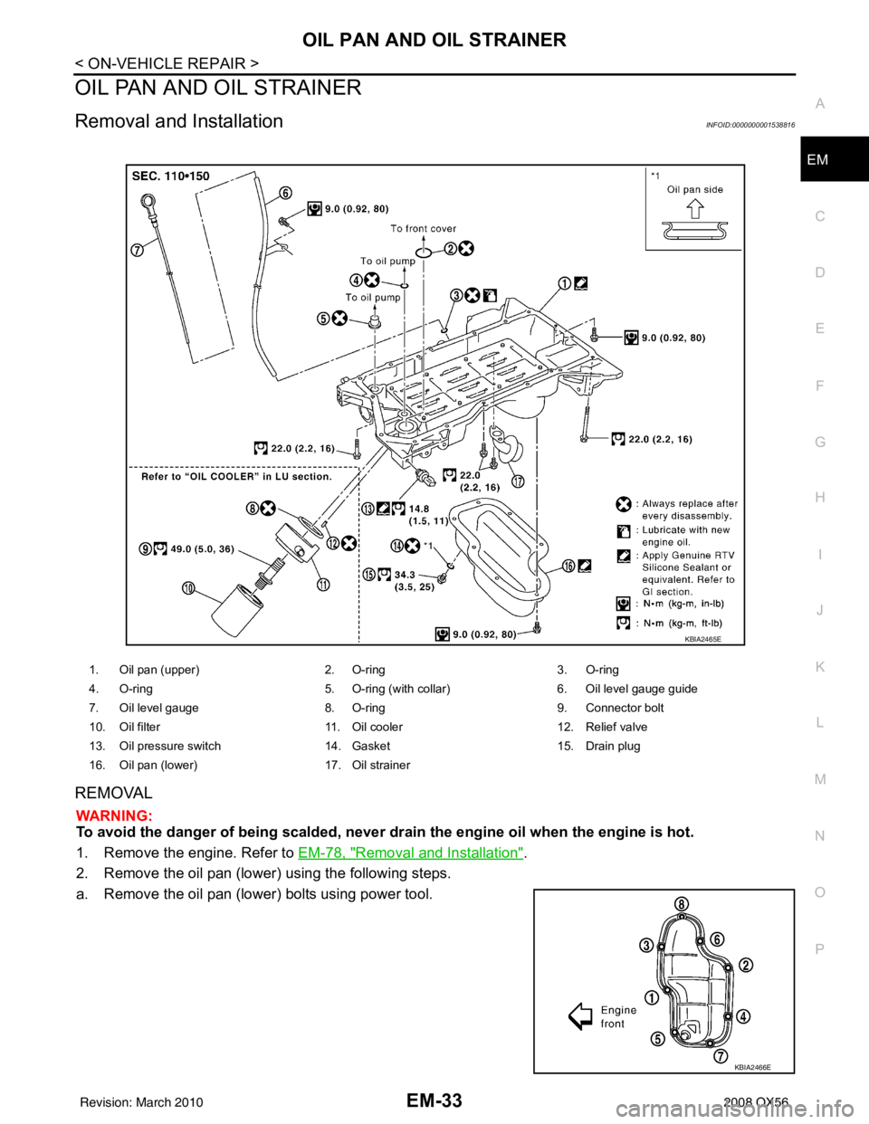
Removal and InstallationINFOID:0000000001538816
REMOVAL
WARNING:
To avoid the danger of being scalded, never drain the engine oil when the engine is hot.
1. Remove the engine. Refer to
EM-78, "
Removal and Installation".
2. Remove the oil pan (lower) using the following steps.
a. Remove the oil pan (lower) bolts using power tool.
1. Oil pan (upper) 2. O-ring3. O-ring
4. O-ring 5. O-ring (with collar)6. Oil level gauge guide
7. Oil level gauge 8. O-ring9. Connector bolt
10. Oil filter 11. Oil cooler12. Relief valve
13. Oil pressure switch 14. Gasket15. Drain plug
16. Oil pan (lower) 17. Oil strainer
KBIA2465E
KBIA2466E
Revision: March 2010 2008 QX56
Page 2171 of 4083

PRECAUTIONSGI-29
< PRECAUTION >
C
DE
F
G H
I
J
K L
M B
GI
N
O P
Dispose of used oil and used oil filters through authorized waste disposal contractors to licensed waste dis-
posal sites, or to the waste oil reclamation trade. If in doubt, contact the local authority for advice on disposal
facilities.
It is illegal to pour used oil on to the ground, down sewers or drains, or into water sources.
The regulations concerning po llution vary between regions.
Air ConditioningINFOID:0000000001539216
Use an approved refrigerant recovery unit any time t he air conditioning system must be discharged. Refer to
HA-20, "
HFC-134a (R-134a) Service Procedure".
Revision: March 2010 2008 QX56
Page 2582 of 4083

LU-1
ENGINE
C
DE
F
G H
I
J
K L
M
SECTION LU
A
LU
N
O P
CONTENTS
ENGINE LUBRICATION SYSTEM
PRECAUTION ....... ........................................2
PRECAUTIONS .............................................. .....2
Precaution for Supplemental Restraint System
(SRS) "AIR BAG" and "SEAT BELT PRE-TEN-
SIONER" ............................................................. ......
2
Precaution Necessary for Steering Wheel Rota-
tion After Battery Disconnect ............................... ......
2
Precaution for Liquid Gasket .....................................3
PREPARATION ............................................4
PREPARATION .............................................. .....4
Special Service Tool ........................................... ......4
Commercial Service Tool ..........................................4
FUNCTION DIAGNOSIS ...............................6
LUBRICATION SYSTEM ............................... .....6
Lubrication Circuit ............................................... ......6
Schematic .................................................................7
ON-VEHICLE MAINTENANCE .....................8
ENGINE OIL ................................................... .....8
Inspection ............................................................ .....8
Changing Engine Oil .................................................9
OIL FILTER .......................................................11
Removal and Installation .........................................11
ON-VEHICLE REPAIR .................................12
OIL COOLER ....................................................12
Removal and Installation ..................................... ....12
OIL PUMP .........................................................14
Removal and Installation .........................................14
DISASSEMBLY AND ASSEMBLY ..............15
OIL PUMP .........................................................15
Disassembly and Assembly ................................. ....15
SERVICE DATA AND SPECIFICATIONS
(SDS) ............... .......................................... ...
17
SERVICE DATA AND SPECIFICATIONS
(SDS) .................................................................
17
Standard and Limit .............................................. ....17
Revision: March 2010 2008 QX56