2008 INFINITI QX56 dimensions
[x] Cancel search: dimensionsPage 1880 of 4083
CYLINDER HEADEM-77
< ON-VEHICLE REPAIR >
C
DE
F
G H
I
J
K L
M A
EM
NP
O
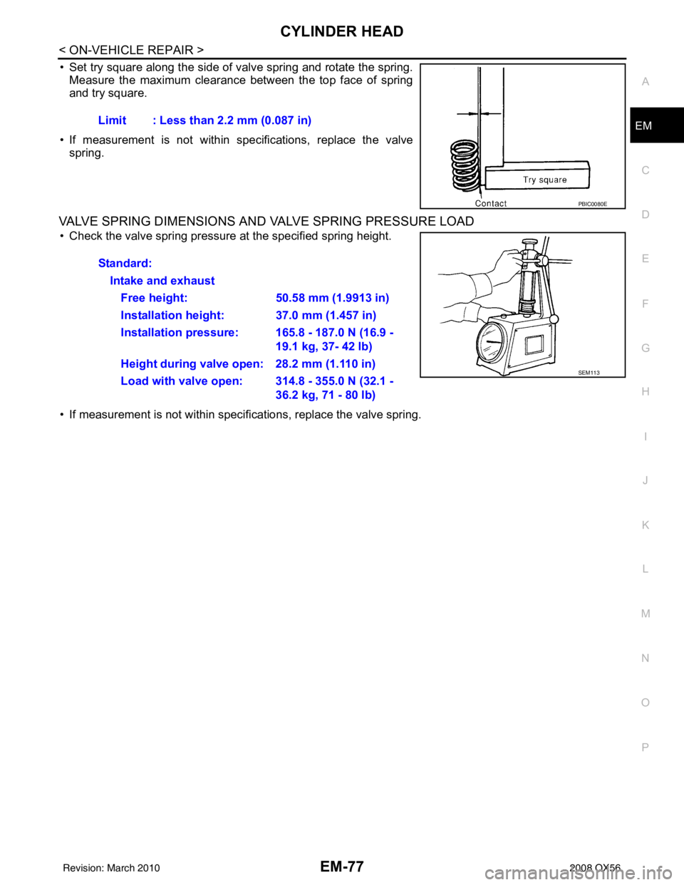
• Set try square along the side of valve spring and rotate the spring.
Measure the maximum clearance between the top face of spring
and try square.
• If measurement is not within specifications, replace the valve spring.
VALVE SPRING DIMENSIONS AND VALVE SPRING PRESSURE LOAD
• Check the valve spring pressure at the specified spring height.
• If measurement is not within specifications, replace the valve spring. Limit : Less than 2.2 mm (0.087 in)
PBIC0080E
Standard:
Intake and exhaustFree height: 50.58 mm (1.9913 in)
Installation height: 37.0 mm (1.457 in)
Installation pressure: 165.8 - 187.0 N (16.9 - 19.1 kg, 37- 42 lb)
Height during valve open: 28.2 mm (1.110 in)
Load with valve open: 314.8 - 355.0 N (32.1 - 36.2 kg, 71 - 80 lb)
SEM113
Revision: March 2010 2008 QX56
Page 1900 of 4083

ENGINE UNITEM-97
< DISASSEMBLY AND ASSEMBLY >
C
DE
F
G H
I
J
K L
M A
EM
NP
O
• Measure diameter of crankshaft pin using suitable tool.
• If measurement is out of standard, measure connecting rod bear-
ing oil clearance. Then use undersize bearing. Follow the "CON-
NECTING ROD BUSHING OIL CLEARANCE (SMALL END)"
procedure.
OUT-OF-ROUND AND TAPER OF CRANKSHAFT
• Measure dimensions at four di fferent points as shown on each
journal and pin.
• Out-of-roundness is indicated by the difference in dimension
between ″X″ and ″Y″ at ″A″ and ″B″ .
• Taper is indicated by the difference in dimension between ″A ″ and
″ B″ at ″X ″ and ″Y″ .
• If measured value exceeds the standard, correct or replace crankshaft.
• If corrected, measure the bearing oil clearance of the corrected journal or pin. Then select the main bearing or connecting rod bearing. Follow the "MAIN BEA RING OIL CLEARANCE" or " CONNECTING ROD BEAR-
ING OIL CLEARANCE" procedure.
CRANKSHAFT RUNOUT
• Place a V-block on a precise flat table to support the journals on both ends of the crankshaft.
• Measure at No. 3 journal using suitable tool.
• While rotating crankshaft, read the movement of the pointer.
• Half of the movement shows the runout.
• If measurement exceeds the limit, replace crankshaft.
CONNECTING ROD BEARING OIL CLEARANCE
Method of Measurement
• Install connecting rod bearings to the connecting rod and cap. Tighten connecting rod bolts to the specified
torque. Refer to EM-82, "
Disassembly and Assembly".
Measure inside diameter of connecting rod bearing.
(Oil clearance) = (Inside diameter of connecting rod bearing) –
(Crankshaft pin diameter)
• If clearance cannot be adjusted wit hin the standard, grind crank-
shaft pin and use undersized bearing. Refer to EM-101, "
How to
Select Piston and Bearing".
Standard : 53.956 - 53.974 mm (2.1243 - 2.1250 in)
PBIC0127E
Limit
Out-of-round (Difference between ″X ″ and ″ Y″)
: 0.002 mm (0.0001 in)
Taper (Difference between ″ A″ and ″B ″)
: 0.002 mm (0.0001 in)
PBIC1685E
Limit : Less than 0.05 mm (0.002 in)
PBIC0129E
Standard : 0.020 - 0.039 mm (0.0008 - 0.0015 in)
Limit : 0.055 mm (0.0022 in)
PBIC1642E
Revision: March 2010 2008 QX56
Page 1905 of 4083
EM-102
< DISASSEMBLY AND ASSEMBLY >
HOW TO SELECT PISTON AND BEARING
When Cylinder Block is Reused
1. Measure cylinder block bore diameter.
2. Determine the bore grade by comparing the measurement with the values under the “Cylinder bore diam-
eter” of the piston selection table.
Piston Selection Table
Unit: mm (in)
NOTE:
• The piston is available together with piston pin as an assembly.
• The piston pin (piston pin bore) grade is provided only for the parts installed at the plant. For service parts, no grades can be selected (only 0 grade is available).
• Hone the cylinder to obtain specified clearance between the piston and cylinder bore.
HOW TO SELECT CONNECTING ROD BEARING
When New Connecting Rod and Crankshaft are Used
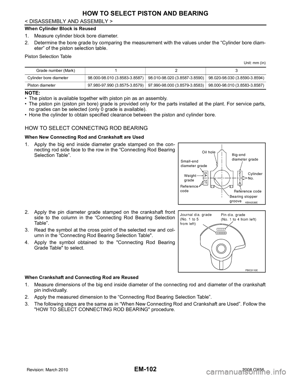
1. Apply the big end inside diameter grade stamped on the con- necting rod side face to the row in the “Connecting Rod Bearing
Selection Table”.
2. Apply the pin diameter grade stamped on the crankshaft front side to the column in the “Connecting Rod Bearing Selection
Table”.
3. Read the symbol at the cross point of the selected row and col-
umn in the “Connecting Rod Bearing Selection Table".
4. Apply the symbol obtained to the "Connecting Rod Bearing Grade Table" to select.
When Crankshaft and Connecting Rod are Reused
1. Measure dimensions of the big end inside diameter of the connecting rod and diameter of the crankshaftpin individually.
2. Apply the measured dimension to the “Connecting Rod Bearing Selection Table”.
3. The following steps are the same as in “When New Connecting Rod and Crankshaft are Used”. Follow the "HOW TO SELECT CONNECTING ROD BEARING" procedure.
Grade number (Mark) 12 3
Cylinder bore diameter 98.000-98.010 (3.8583-3.8587) 98.010-98.020 (3.8587-3.8590) 98.020-98.030 (3.8590-3.8594)
Piston diameter 97.980-97.990 (3.8575-3.8579) 97.990-98.000 (3.8579-3.8583) 98.000-98.010 (3.8583-3.8587)
KBIA2536E
PBIC0110E
Revision: March 2010 2008 QX56
Page 1914 of 4083
SERVICE DATA AND SPECIFICATIONS (SDS)EM-111
< SERVICE DATA AND SPECIFICATIONS (SDS)
C
DE
F
G H
I
J
K L
M A
EM
NP
O
Unit: mm (in)
Spark Plug Tube
Unit: mm (in)
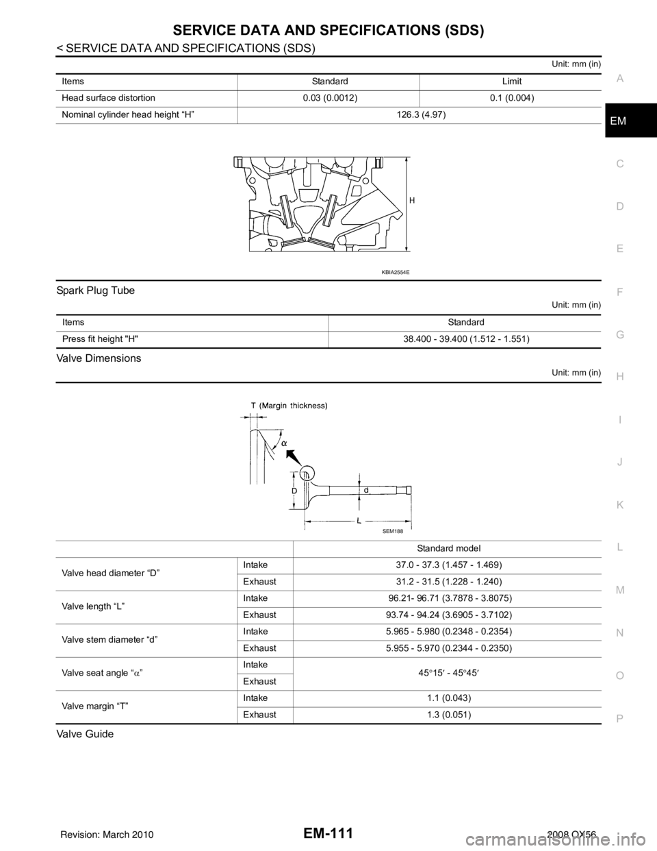
Valve Dimensions
Unit: mm (in)
Valve Guide
Items
StandardLimit
Head surface distortion 0.03 (0.0012)0.1 (0.004)
Nominal cylinder head height “H” 126.3 (4.97)
KBIA2554E
Items Standard
Press fit height "H" 38.400 - 39.400 (1.512 - 1.551)
Standard model
Valve head diameter “D” Intake
37.0 - 37.3 (1.457 - 1.469)
Exhaust 31.2 - 31.5 (1.228 - 1.240)
Valve length “L” Intake
96.21- 96.71 (3.7878 - 3.8075)
Exhaust 93.74 - 94.24 (3.6905 - 3.7102)
Valve stem diameter “d” Intake
5.965 - 5.980 (0.2348 - 0.2354)
Exhaust 5.955 - 5.970 (0.2344 - 0.2350)
Valve seat angle “ α” Intake
45°15 ′ - 45 °45 ′
Exhaust
Valve margin “T” Intake
1.1 (0.043)
Exhaust 1.3 (0.051)
SEM188
Revision: March 2010 2008 QX56
Page 1924 of 4083
PRECAUTIONSEX-3
< PRECAUTION >
C
DE
F
G H
I
J
K L
M A
EX
NP
O
5. When the repair work is completed, return the ignition switch to the
″LOCK ″ position before connecting
the battery cables. (At this time, the steering lock mechanism will engage.)
6. Perform a self-diagnosis check of al l control units using CONSULT-III.
Precaution for Liquid GasketINFOID:0000000001538868
REMOVAL OF LIQUID GASKET SEALING
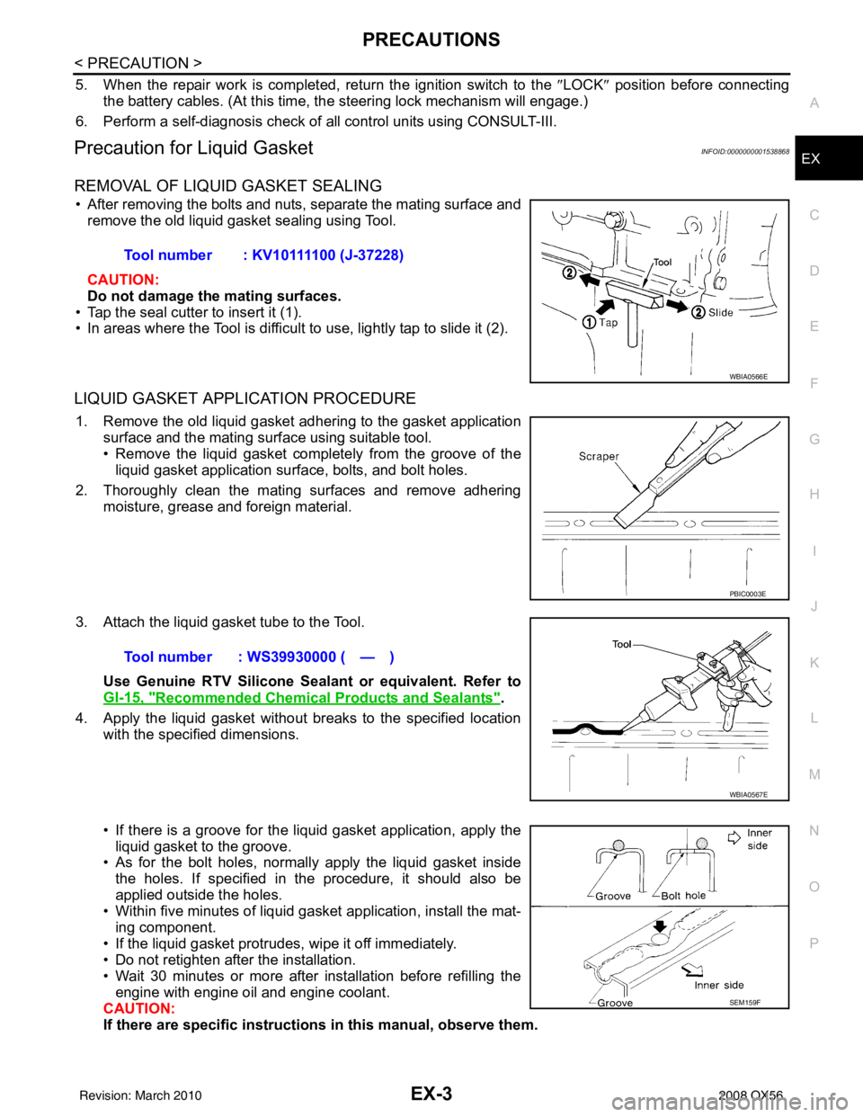
• After removing the bolts and nuts, separate the mating surface and
remove the old liquid gasket sealing using Tool.
CAUTION:
Do not damage the mating surfaces.
• Tap the seal cutter to insert it (1).
• In areas where the Tool is difficult to use, lightly tap to slide it (2).
LIQUID GASKET APPLICATION PROCEDURE
1. Remove the old liquid gasket adhering to the gasket application surface and the mating surface using suitable tool.
• Remove the liquid gasket completely from the groove of the
liquid gasket application surface, bolts, and bolt holes.
2. Thoroughly clean the mating surfaces and remove adhering moisture, grease and foreign material.
3. Attach the liquid gasket tube to the Tool. Use Genuine RTV Silicone Sealant or equivalent. Refer to
GI-15, "
Recommended Chemical Products and Sealants".
4. Apply the liquid gasket without breaks to the specified location with the specified dimensions.
• If there is a groove for the liquid gasket application, apply theliquid gasket to the groove.
• As for the bolt holes, normally apply the liquid gasket inside
the holes. If specified in the procedure, it should also be
applied outside the holes.
• Within five minutes of liquid gasket application, install the mat-
ing component.
• If the liquid gasket protrudes, wipe it off immediately.
• Do not retighten after the installation.
• Wait 30 minutes or more after installation before refilling the engine with engine oil and engine coolant.
CAUTION:
If there are specific instructions in this manual, observe them.
Tool number : KV10111100 (J-37228)
WBIA0566E
PBIC0003E
Tool number : WS39930000 ( — )
WBIA0567E
SEM159F
Revision: March 2010
2008 QX56
Page 2143 of 4083
GI-1
GENERAL INFORMATION
C
DE
F
G H
I
J
K L
M B
GI
SECTION GI
N
O P
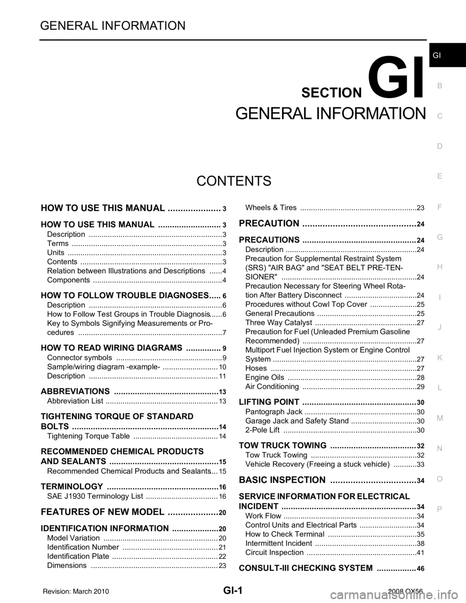
CONTENTS
GENERAL INFORMATION
HOW TO USE THIS MANU AL ......................3
HOW TO USE THIS MANUAL ....................... .....3
Description .......................................................... ......3
Terms ........................................................................3
Units ..........................................................................3
Contents ....................................................................3
Relation between Illustrations and Descriptions .......4
Components ..............................................................4
HOW TO FOLLOW TROUBLE DIAGNOSES .....6
Description ................................................................6
How to Follow Test Groups in Trouble Diagnosis ......6
Key to Symbols Signifying Measurements or Pro-
cedures ............................................................... ......
7
HOW TO READ WIRING DIAGRAMS ................9
Connector symbols ............................................. ......9
Sample/wiring diagram -example- ...........................10
Description ..............................................................11
ABBREVIATIONS .......................................... ....13
Abbreviation List .................................................. ....13
TIGHTENING TORQUE OF STANDARD
BOLTS ................................................................
14
Tightening Torque Table .........................................14
RECOMMENDED CHEMICAL PRODUCTS
AND SEALANTS ............................................ ....
15
Recommended Chemical Products and Sealants ....15
TERMINOLOGY .................................................16
SAE J1930 Terminology List ............................... ....16
FEATURES OF NEW MODEL .....................20
IDENTIFICATION INFORMATION .....................20
Model Variation ................................................... ....20
Identification Number ..............................................21
Identification Plate ...................................................22
Dimensions .............................................................23
Wheels & Tires .................................................... ....23
PRECAUTION ..............................................24
PRECAUTIONS .................................................24
Description ........................................................... ....24
Precaution for Supplemental Restraint System
(SRS) "AIR BAG" and "SEAT BELT PRE-TEN-
SIONER" .................................................................
24
Precaution Necessary for Steering Wheel Rota-
tion After Battery Disconnect ...................................
24
Procedures without Cowl Top Cover .......................25
General Precautions ................................................25
Three Way Catalyst .................................................27
Precaution for Fuel (Unleaded Premium Gasoline
Recommended) .......................................................
27
Multiport Fuel Injection System or Engine Control
System .....................................................................
27
Hoses ......................................................................27
Engine Oils ..............................................................28
Air Conditioning .......................................................29
LIFTING POINT .................................................30
Pantograph Jack ......................................................30
Garage Jack and Safety Stand ................................30
2-Pole Lift ................................................................30
TOW TRUCK TOWING .....................................32
Tow Truck Towing ...................................................32
Vehicle Recovery (Freeing a stuck vehicle) ............33
BASIC INSPECTION ...................................34
SERVICE INFORMATION FOR ELECTRICAL
INCIDENT ..........................................................
34
Work Flow ............................................................ ....34
Control Units and Electrical Parts ............................34
How to Check Terminal ...........................................35
Intermittent Incident ............................................. ....38
Circuit Inspection .....................................................41
CONSULT-III CHECKING SYSTEM .................46
Revision: March 2010 2008 QX56
Page 2165 of 4083
IDENTIFICATION INFORMATIONGI-23
< FEATURES OF NEW MODEL >
C
DE
F
G H
I
J
K L
M B
GI
N
O P
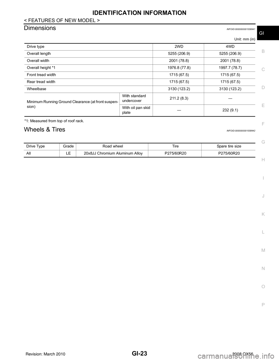
DimensionsINFOID:0000000001559941
Unit: mm (in)
*1: Measured from top of roof rack.
Wheels & TiresINFOID:0000000001559942
Drive type 2WD 4WD
Overall length 5255 (206.9)5255 (206.9)
Overall width 2001 (78.8)2001 (78.8)
Overall height *1 1976.8 (77.8)1997.7 (78.7)
Front tread width 1715 (67.5)1715 (67.5)
Rear tread width 1715 (67.5)1715 (67.5)
Wheelbase 3130 (123.2)3130 (123.2)
Minimum Running Ground Clearance (at front suspen-
sion) With standard
undercover
211.2 (8.3)
—
With oil pan skid
plate —2
32 ( 9.1 )
Drive Type Grade Road wheelTireSpare tire size
All LE 20x8JJ Chromium Aluminum Alloy P275/60R20P275/60R20
Revision: March 2010 2008 QX56
Page 2584 of 4083
PRECAUTIONSLU-3
< PRECAUTION >
C
DE
F
G H
I
J
K L
M A
LU
NP
O
5. When the repair work is completed, return the ignition switch to the
″LOCK ″ position before connecting
the battery cables. (At this time, the steering lock mechanism will engage.)
6. Perform a self-diagnosis check of al l control units using CONSULT-III.
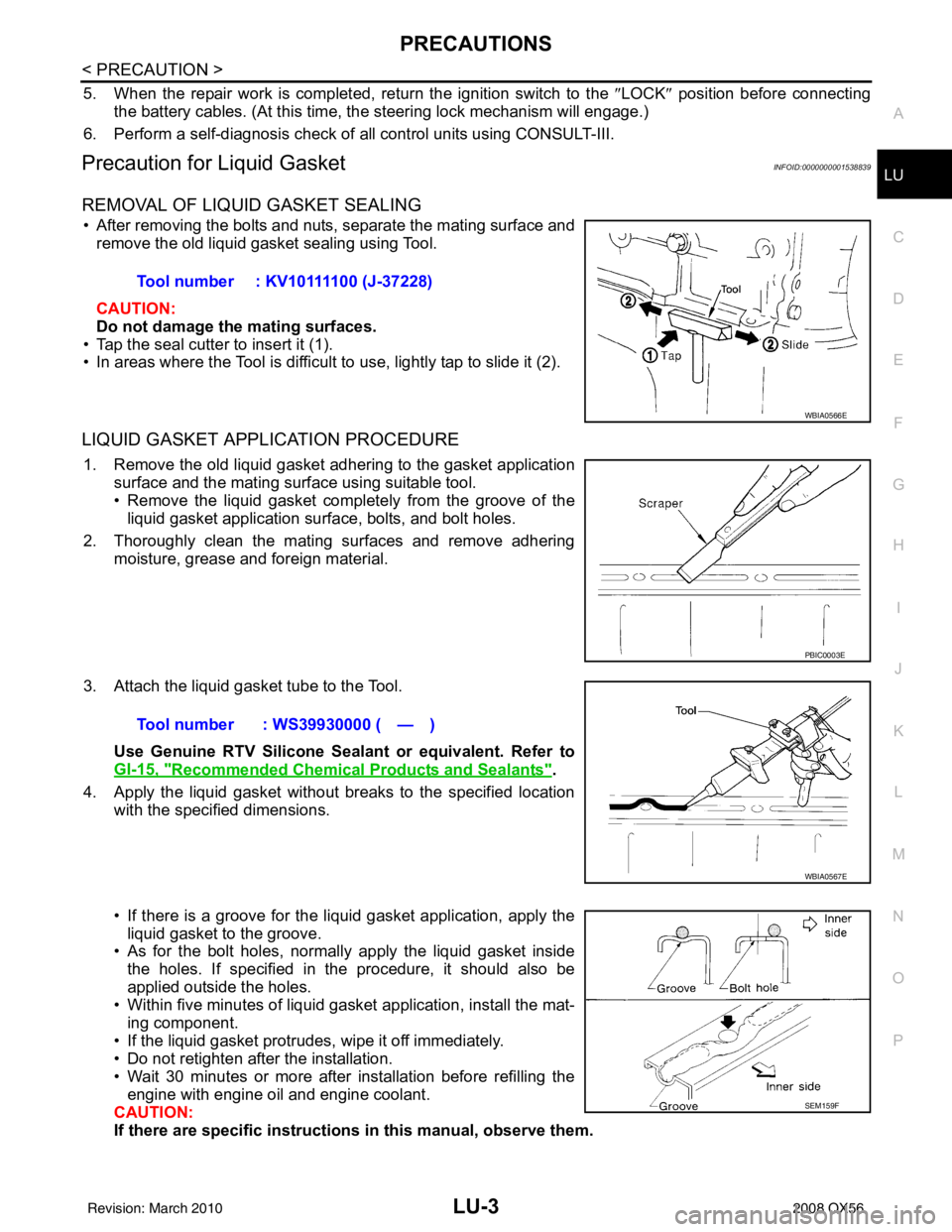
Precaution for Liquid GasketINFOID:0000000001538839
REMOVAL OF LIQUID GASKET SEALING
• After removing the bolts and nuts, separate the mating surface and
remove the old liquid gasket sealing using Tool.
CAUTION:
Do not damage the mating surfaces.
• Tap the seal cutter to insert it (1).
• In areas where the Tool is difficult to use, lightly tap to slide it (2).
LIQUID GASKET APPLICATION PROCEDURE
1. Remove the old liquid gasket adhering to the gasket application surface and the mating surface using suitable tool.
• Remove the liquid gasket completely from the groove of the
liquid gasket application surface, bolts, and bolt holes.
2. Thoroughly clean the mating surfaces and remove adhering moisture, grease and foreign material.
3. Attach the liquid gasket tube to the Tool. Use Genuine RTV Silicone Sealant or equivalent. Refer to
GI-15, "
Recommended Chemical Products and Sealants".
4. Apply the liquid gasket without breaks to the specified location with the specified dimensions.
• If there is a groove for the liquid gasket application, apply theliquid gasket to the groove.
• As for the bolt holes, normally apply the liquid gasket inside
the holes. If specified in the procedure, it should also be
applied outside the holes.
• Within five minutes of liquid gasket application, install the mat-
ing component.
• If the liquid gasket protrudes, wipe it off immediately.
• Do not retighten after the installation.
• Wait 30 minutes or more after installation before refilling the engine with engine oil and engine coolant.
CAUTION:
If there are specific instructions in this manual, observe them.
Tool number : KV10111100 (J-37228)
WBIA0566E
PBIC0003E
Tool number : WS39930000 ( — )
WBIA0567E
SEM159F
Revision: March 2010
2008 QX56