2008 INFINITI QX56 oil pressure
[x] Cancel search: oil pressurePage 3526 of 4083
POWER STEERING OIL PUMPST-35
< DISASSEMBLY AND ASSEMBLY >
C
DE
F
H I
J
K L
M A
B
ST
N
O P
POWER STEERING OIL PUMP
Disassembly and AssemblyINFOID:0000000004920106
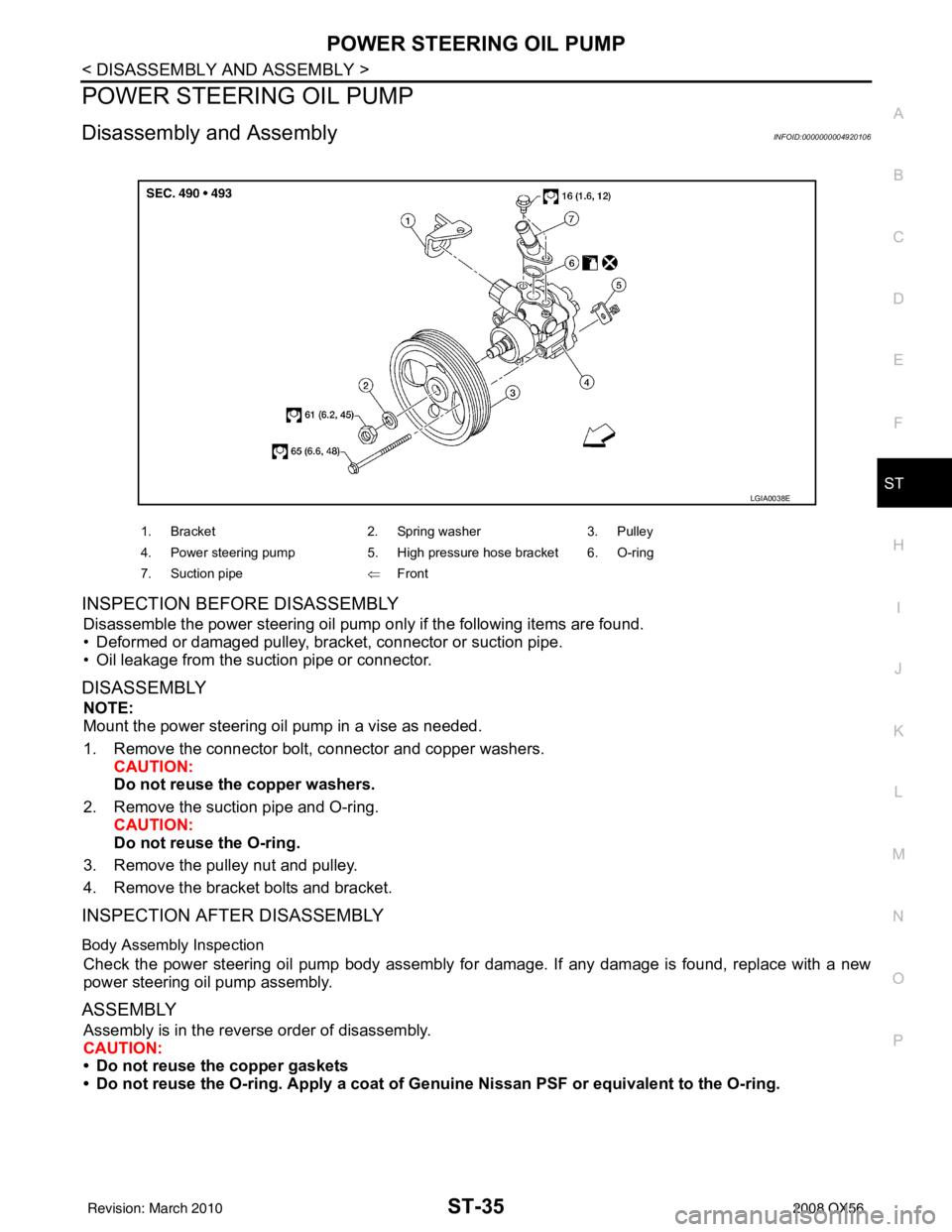
INSPECTION BEFORE DISASSEMBLY
Disassemble the power steering oil pump only if the following items are found.
• Deformed or damaged pulley, bracket, connector or suction pipe.
• Oil leakage from the suction pipe or connector.
DISASSEMBLY
NOTE:
Mount the power steering oil pump in a vise as needed.
1. Remove the connector bolt, connector and copper washers. CAUTION:
Do not reuse the copper washers.
2. Remove the suction pipe and O-ring. CAUTION:
Do not reuse the O-ring.
3. Remove the pulley nut and pulley.
4. Remove the bracket bolts and bracket.
INSPECTION AFTER DISASSEMBLY
Body Assembly Inspection
Check the power steering oil pump body assembly fo r damage. If any damage is found, replace with a new
power steering oil pump assembly.
ASSEMBLY
Assembly is in the reverse order of disassembly.
CAUTION:
• Do not reuse the copper gaskets
• Do not reuse the O-ring. Apply a coat of Genuine Nissan PSF or equivalent to the O-ring.
1. Bracket 2. Spring washer3. Pulley
4. Power steering pump 5. High pressure hose bracket 6. O-ring
7. Suction pipe ⇐Front
LGIA0038E
Revision: March 2010 2008 QX56
Page 3529 of 4083

ST-38
< SERVICE DATA AND SPECIFICATIONS (SDS)
SERVICE DATA AND SPECIFICATIONS (SDS)
Oil Pump
INFOID:0000000001534689
Steering FluidINFOID:0000000001534690
Rack sliding force At the neutral point:
Range within
± 11.5 mm
(± 0.453 in) from the neutral
position
(in power ON) Area average value 147
− 211 N (14.99 − 21.52 kg, 33.1 − 47.52 lb)
Allowable variation 98 N (10 kg, 22 lb) or less
Whole area (in power OFF) Peak value
294 N (30.0 kg, 66 lb) or less
Allowable variation 147 N (16 kg, 35 lb) or less
Steering gear model
PR26AM
Relief oil pressure
9.0 − 9.8 mPa (91.77 − 99.93 kg/cm2, 1305.34 − 1421.37 psi)
Fluid capacity
Approx. 1.0 (1-1/8 US qt, 7/8 Imp qt)
Revision: March 2010 2008 QX56
Page 3551 of 4083

TM-4
Precaution for Supplemental Restraint System
(SRS) "AIR BAG" and "SEAT BELT PRE-TEN-
SIONER" ................................................................
173
Precaution Necessary for Steering Wheel Rota-
tion After Battery Disconnect .................................
173
Precaution for On Board Diagnosis (OBD) System
of A/T and Engine ..................................................
174
Precaution .............................................................174
Service Notice or Precaution .................................175
PREPARATION ..........................................176
PREPARATION .............................................. .176
Special Service Tool ............................................ ..176
Commercial Service Tool ......................................177
ON-VEHICLE MAINTENANCE ..................178
A/T FLUID ....................................................... .178
Checking the A/T Fluid (ATF) .............................. ..178
Changing the A/T Fluid (ATF) ................................180
A/T FLUID COOLER ........................................182
A/T Fluid Cooler Cleaning ................................... ..182
Inspection ..............................................................184
STALL TEST ....................................................185
Inspection and Judgment .................................... ..185
LINE PRESSURE TEST ..................................187
Inspection and Judgment .................................... ..187
ROAD TEST .....................................................189
Description ........................................................... ..189
Check Before Engine Is Started ............................189
Check At Idle ....................................................... ..189
Cruise Test - Part 1 ...............................................190
Cruise Test - Part 2 ...............................................192
Cruise Test - Part 3 ...............................................193
Vehicle Speed When Shifting Gears .....................193
Vehicle Speed When Performing and Releasing
Complete Lock-up .................................................
193
A/T POSITION .................................................194
Checking of A/T Position ..................................... ..194
Adjustment of A/T Position ....................................194
ON-VEHICLE REPAIR ...............................195
SHIFT CONTROL SYSTEM ........................... .195
A/T Shift Selector Removal and Installation ..........195
Checking of A/T Position ..................................... ..196
Adjustment of A/T Position ....................................196
AIR BREATHER HOSE ...................................197
Removal and Installation ..................................... ..197
OIL PAN ...........................................................199
Oil Pan ................................................................. .199
CONTROL VALVE WITH TCM ........................201
Control Valve with TCM and A/T Fluid Tempera-
ture Sensor 2 ....................................................... .
201
REAR OIL SEAL ..............................................213
Rear Oil Seal ........................................................ .213
REMOVAL AND INSTALLATION .............214
TRANSMISSION ASSEMBLY ........................ ..214
Removal and Installation (2WD) .......................... .214
Removal and Installation (4WD) ...........................216
DISASSEMBLY AND ASSEMBLY ...........220
OVERHAUL ......................................................220
Component .......................................................... .220
Oil Channel ...........................................................227
Location of Adjusting Shims, Needle Bearings,
Thrust Washers and Snap Rings ......................... .
229
DISASSEMBLY .............................................. ..232
Disassembly ......................................................... .232
REPAIR FOR COMPONENT PARTS ..............250
Oil Pump .............................................................. .250
Front Sun Gear, 3rd One-Way Clutch ...................252
Front Carrier, Input Clutch, Rear Internal Gear .....254
Mid Sun Gear, Rear Sun Gear, High and Low Re-
verse Clutch Hub ................................................. .
259
High and Low Reverse Clutch ..............................264
Direct Clutch .........................................................266
ASSEMBLY .................................................... ..269
Assembly (1) ........................................................ .269
Adjustment ............................................................282
Assembly (2) .........................................................284
SERVICE DATA AND SPECIFICATIONS
(SDS) ........ .................................................
291
SERVICE DATA AND SPECIFICATIONS
(SDS) .............................................................. ..
291
General Specification ........................................... .291
Vehicle Speed at Which Gear Shifting Occurs .....291
Vehicle Speed at Which Lock-up Occurs/Releas-
es ......................................................................... .
291
Stall Speed ............................................................292
Line Pressure ........................................................292
A/T Fluid Temperature Sensor ..............................292
Input Speed Sensor ..............................................292
Output Speed Sensor ...........................................292
Reverse Brake ......................................................292
Total End Play .......................................................292
Torque Converter ..................................................293
Revision: March 2010 2008 QX56
Page 3570 of 4083
A/T CONTROL SYSTEMTM-23
< FUNCTION DIAGNOSIS >
CEF
G H
I
J
K L
M A
B
TM
N
O P
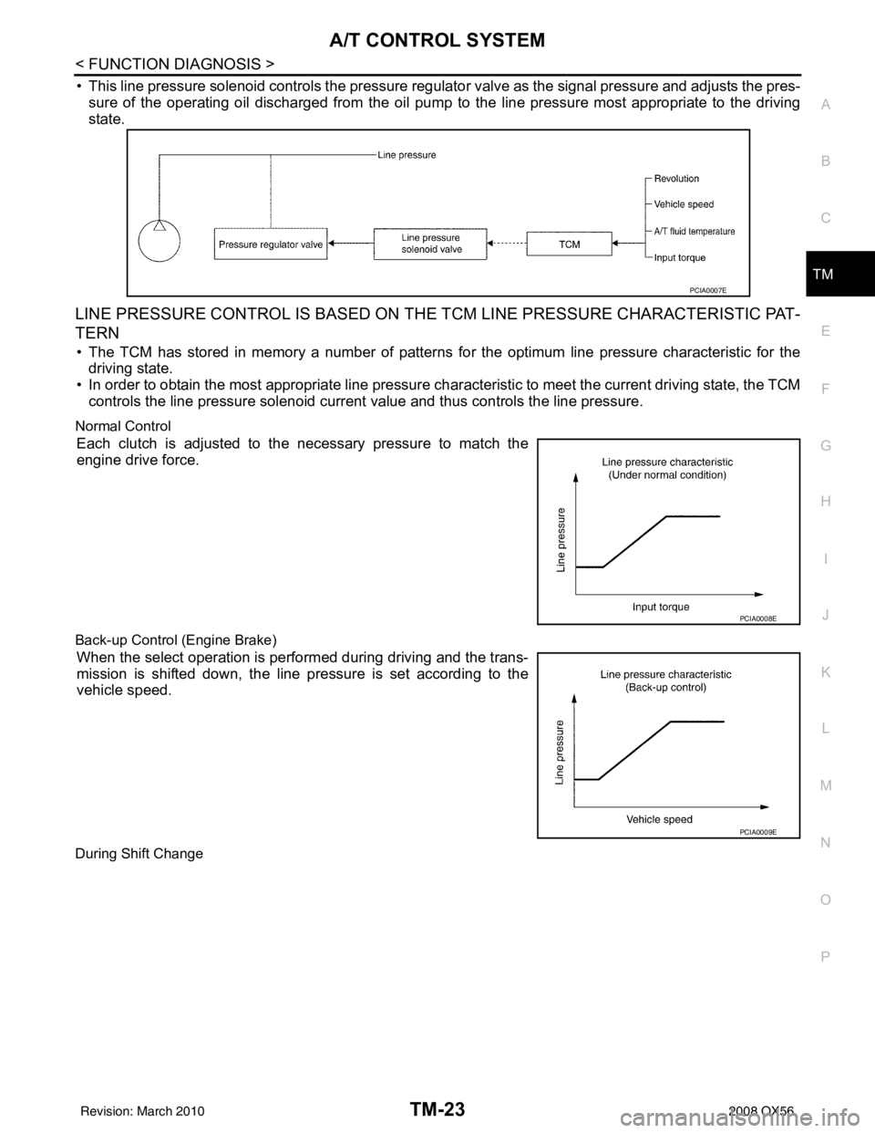
• This line pressure solenoid controls the pressure regulat or valve as the signal pressure and adjusts the pres-
sure of the operating oil discharged from the oil pump to the line pressure most appropriate to the driving
state.
LINE PRESSURE CONTROL IS BASED ON THE TCM LINE PRESSURE CHARACTERISTIC PAT-
TERN
• The TCM has stored in memory a number of patterns fo r the optimum line pressure characteristic for the
driving state.
• In order to obtain the most appropriate line pressure char acteristic to meet the current driving state, the TCM
controls the line pressure solenoid current value and thus controls the line pressure.
Normal Control
Each clutch is adjusted to the necessary pressure to match the
engine drive force.
Back-up Control (Engine Brake)
When the select operation is performed during driving and the trans-
mission is shifted down, the line pressure is set according to the
vehicle speed.
During Shift Change
PCIA0007E
PCIA0008E
PCIA0009E
Revision: March 2010 2008 QX56
Page 3571 of 4083
TM-24
< FUNCTION DIAGNOSIS >
A/T CONTROL SYSTEM
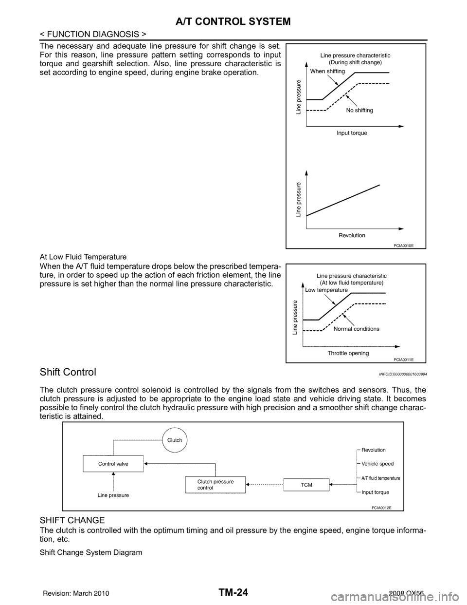
The necessary and adequate line pressure for shift change is set.
For this reason, line pressure pattern setting corresponds to input
torque and gearshift selection. Also, line pressure characteristic is
set according to engine speed, during engine brake operation.
At Low Fluid Temperature
When the A/T fluid temperature drops below the prescribed tempera-
ture, in order to speed up the action of each friction element, the line
pressure is set higher than the normal line pressure characteristic.
Shift ControlINFOID:0000000001603994
The clutch pressure control solenoid is controlled by the signals from the switches and sensors. Thus, the
clutch pressure is adjusted to be appropriate to the engine load state and vehicle driving state. It becomes
possible to finely control the clutch hydraulic pressure with high precision and a smoother shift change charac-
teristic is attained.
SHIFT CHANGE
The clutch is controlled with the optimum timing and oil pressure by the engine speed, engine torque informa-
tion, etc.
Shift Change System Diagram
PCIA0010E
PCIA0011E
PCIA0012E
Revision: March 2010 2008 QX56
Page 3572 of 4083
A/T CONTROL SYSTEMTM-25
< FUNCTION DIAGNOSIS >
CEF
G H
I
J
K L
M A
B
TM
N
O P
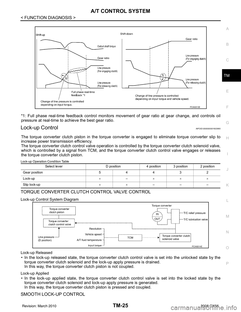
*1: Full phase real-time feedback control monitors move ment of gear ratio at gear change, and controls oil
pressure at real-time to achieve the best gear ratio.
Lock-up ControlINFOID:0000000001603995
The torque converter clutch piston in the torque conv erter is engaged to eliminate torque converter slip to
increase power transmission efficiency.
The torque converter clutch control valve operation is controlled by the torque conver ter clutch solenoid valve,
which is controlled by a signal from TCM, and the torque converter clutch control valve engages or releases
the torque converter clutch piston.
Lock-up Operation Condition Table
TORQUE CONVERTER CLUTCH CONTROL VALVE CONTROL
Lock-up Control System Diagram
Lock-up Released
• In the lock-up released state, the torque converter clutch control valve is set into the unlocked state by the
torque converter clutch solenoid and the lock-up apply pressure is drained.
In this way, the torque converter clutch piston is not coupled.
Lock-up Applied
• In the lock-up applied state, the torque converter clutch control valve is set into the locked state by the
torque converter clutch solenoid and lock-up apply pressure is generated.
In this way, the torque converter clutch piston is pressed and coupled.
SMOOTH LOCK-UP CONTROL
PCIA0013E
Select lever D position4 position 3 position 2 position
G ear p osit io n 54432
Lock-up ×– ×××
Slip lock-up ××–––
PCIA0014E
Revision: March 2010 2008 QX56
Page 3573 of 4083
TM-26
< FUNCTION DIAGNOSIS >
A/T CONTROL SYSTEM
When shifting from the lock-up released state to the lock-up applied state, the current output to the torque con-
verter clutch solenoid is controlled with the TCM. In th is way, when shifting to the lock-up applied state, the
torque converter clutch is temporarily set to the half-clutched state to reduce the shock.
Half-clutched State
• The current output from the TCM to the torque converte r clutch solenoid is varied to gradually increase the
torque converter clutch solenoid pressure.
In this way, the lock-up apply pressure gradually rises and while the torque converter clutch piston is put into
half-clutched status, the torque converter clutch piston operating pressure is increased and the coupling is
completed smoothly.
Slip Lock-up Control
• In the slip region, the torque converter clutch solenoid current is controlled with the TCM to put it into the
half-clutched state. This absorbs the engine tor que fluctuation and lock-up operates from low speed.
This raises the fuel efficiency for 4GR and 5GR at both low speed and when the accelerator has a low
degree of opening.
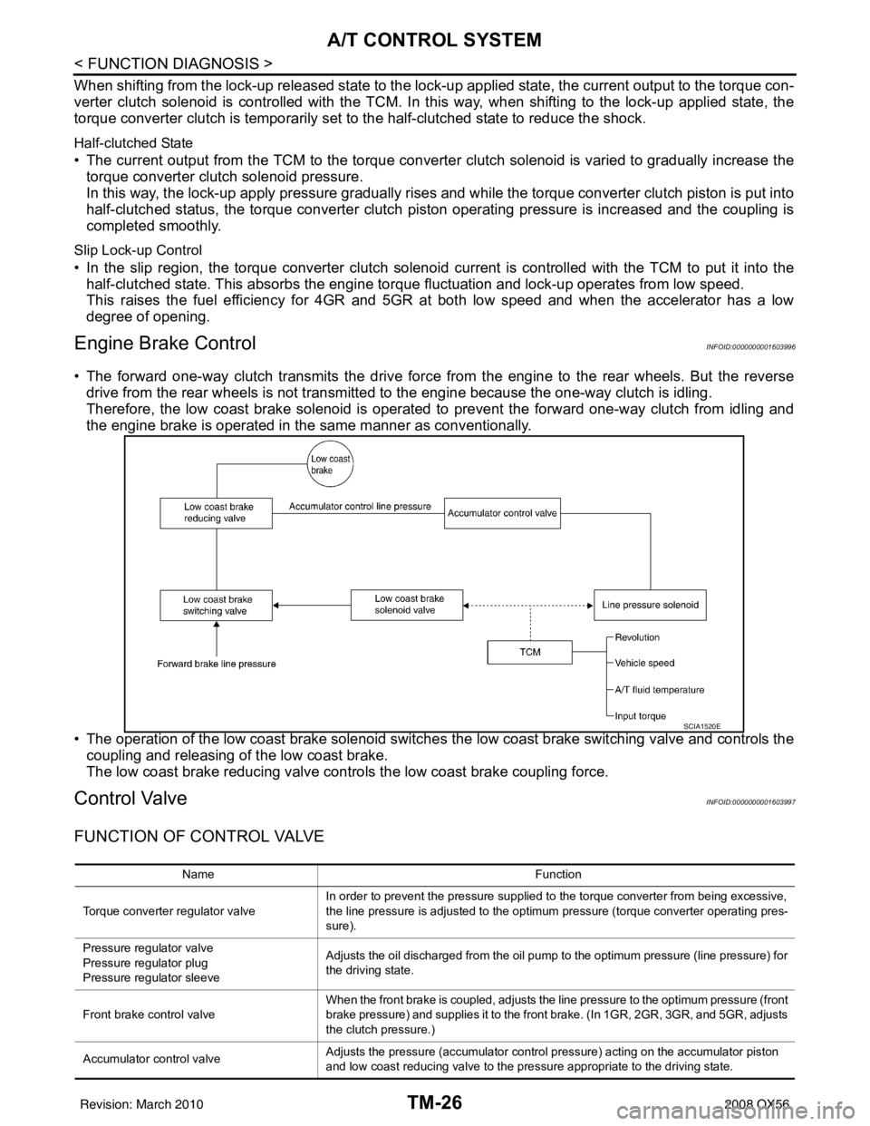
Engine Brake ControlINFOID:0000000001603996
• The forward one-way clutch transmits the drive force from the engine to the rear wheels. But the reverse drive from the rear wheels is not transmitted to the engine because the one-way clutch is idling.
Therefore, the low coast brake solenoid is operated to prevent the forward one-way clutch from idling and
the engine brake is operated in the same manner as conventionally.
• The operation of the low coast brake solenoid switches the low coast brake switching valve and controls the
coupling and releasing of the low coast brake.
The low coast brake reducing valve contro ls the low coast brake coupling force.
Control ValveINFOID:0000000001603997
FUNCTION OF CONTROL VALVE
SCIA1520E
Name Function
Torque converter regulator valve In order to prevent the pressure supplied to the torque converter from being excessive,
the line pressure is adjusted to the optimum pressure (torque converter operating pres-
sure).
Pressure regu lator valve
Pressure regulator plug
Pressure regu lator sleeve Adjusts the oil discharged from the oil pump to the optimum pressure (line pressure) for
the driving state.
Front brake control valve When the front brake is coupled, adjusts the line pressure to the optimum pressure (front
brake pressure) and supplies it to the front brake. (In 1GR, 2GR, 3GR, and 5GR, adjusts
the clutch pressure.)
Accumulator control valve Adjusts the pressure (accumulator control pressure) acting on the accumulator piston
and low coast reducing valve to the pressure appropriate to the driving state.
Revision: March 2010
2008 QX56
Page 3574 of 4083

A/T CONTROL SYSTEMTM-27
< FUNCTION DIAGNOSIS >
CEF
G H
I
J
K L
M A
B
TM
N
O P
FUNCTION OF PRESSURE SWITCH
Pilot valve A Adjusts the line pressure and produces the constant pressure (pilot pressure) required
for line pressure control, shift change control, and lock-up control.
Pilot valve B Adjusts the line pressure and produces the constant pressure (pilot pressure) required
for shift change control.
Low coast brake switching valve During engine braking, supplies the line pressure to the low coast brake reducing valve.
Low coast brake reducing valve When the low coast brake is coupled, adjusts the line pressure to the optimum pressure
(low coast brake pressure) and supplies it to the low coast brake.
N-R accumulator Produces the stabilizing pressure for when N-R is selected.
Direct clutch piston switching valve Operates in 4GR gear and switches the direct clutch coupling capacity.
High and low reverse clutch control valve When the high and low reverse clutch is coupled, adjusts the line pressure to the opti-
mum pressure (high and low reverse clutch pressure) and supplies it to the high and low
reverse clutch. (In 1GR, 3GR, 4GR and 5GR, adjusts the clutch pressure.)
Input clutch control valve When the input clutch is coupled, adjusts the line pressure to the optimum pressure (in-
put clutch pressure) and supplies it to the input clutch. (In 4GR and 5GR, adjusts the
clutch pressure.)
Direct clutch control valve When the direct clutch is coupled, adjusts the line pressure to the optimum pressure (di-
rect clutch pressure) and supplies it to the direct clutch. (In 2GR, 3GR, and 4GR, adjusts
the clutch pressure.)
TCC control valve
TCC control plug
TCC control sleeve Switches the lock-up to operating or released. Also, by performing the lock-up operation
transiently, lock-up smoothly.
Torque converter lubrication valve Operates during lock-up to switch the torque converter, cooling, and lubrication system
oil path.
Cool bypass valve Allows excess oil to bypass cooler circuit without being fed into it.
Line pressure relief valve Discharges excess oil from line pressure circuit.
N-D accumulator Produces the stabilizing pressure for when N-D is selected.
Manual valve Sends line pressure to each circuit according to the select position. The circuits to which
the line pressure is not sent drain.
Name
Function
Name Function
Pressure switch 2 (LC/B) Detects any malfunction in the low coast brake hydraulic pressure. When it detects any
malfunction, it puts the system into fail-safe mode.
Revision: March 2010
2008 QX56