2008 INFINITI QX56 fuse
[x] Cancel search: fusePage 3309 of 4083
![INFINITI QX56 2008 Factory Service Manual IPDM E/R (INTELLIGENT POWER DISTRIBUTION MODULE ENGINE ROOM)
SEC-101
< ECU DIAGNOSIS > [WITH INTELLIGENT KEY SYSTEM]
C
D
E
F
G H
I
J
L
M A
B
SEC
N
O P
Te r m i n a l Wire
color Signal name Signal
inp INFINITI QX56 2008 Factory Service Manual IPDM E/R (INTELLIGENT POWER DISTRIBUTION MODULE ENGINE ROOM)
SEC-101
< ECU DIAGNOSIS > [WITH INTELLIGENT KEY SYSTEM]
C
D
E
F
G H
I
J
L
M A
B
SEC
N
O P
Te r m i n a l Wire
color Signal name Signal
inp](/manual-img/42/57030/w960_57030-3308.png)
IPDM E/R (INTELLIGENT POWER DISTRIBUTION MODULE ENGINE ROOM)
SEC-101
< ECU DIAGNOSIS > [WITH INTELLIGENT KEY SYSTEM]
C
D
E
F
G H
I
J
L
M A
B
SEC
N
O P
Te r m i n a l Wire
color Signal name Signal
input/
output Measuring condition
Reference value(Approx.)
Igni-
tion
switch Operation or condition
1 B/Y Battery power supply Input OFF —Battery voltage
2 R Battery power supply Input OFF —Battery voltage
3BRECM relay Output— Ignition switch ON or START
Battery voltage
Ignition switch OFF or ACC 0V
4W/LECM relay Output— Ignition switch ON or START
Battery voltage
Ignition switch OFF or ACC 0V
6L Throttle control motor
relay Output —Ignition switch ON or START
Battery voltage
Ignition switch OFF or ACC 0V
7 W/B ECM relay control Input — Ignition switch ON or START
0V
Ignition switch OFF or ACC Battery voltage
8 R/B Fuse 54 Output —Ignition switch ON or START
Battery voltage
Ignition switch OFF or ACC 0V
10 G Fuse 45 Output ONDaytime light system active
0V
Daytime light system inactive Battery voltage
11 Y/B A/C compressor Output ON or
START A/C switch ON or defrost A/C
switch
Battery voltage
A/C switch OFF or defrost A/C
switch 0V
12 L/W Ignition switch sup-
plied power Input —OFF or ACC
0V
ON or START Battery voltage
13 B/Y Fuel pump relay Output — Ignition switch ON or START
Battery voltage
Ignition switch OFF or ACC 0V
14 Y/R Fuse 49 Output —Ignition switch ON or START
Battery voltage
Ignition switch OFF or ACC 0V
15 LG/B Fuse 50 (VDC) Output — Ignition switch ON or START
Battery voltage
Ignition switch OFF or ACC 0V
15 GR Fuse 50 (ABS) Output — Ignition switch ON or START
Battery voltage
Ignition switch OFF or ACC 0V
16 G Fuse 51 Output —Ignition switch ON or START
Battery voltage
Ignition switch OFF or ACC 0V
17 W Fuse 55 Output —Ignition switch ON or START
Battery voltage
Ignition switch OFF or ACC 0V
19 W/R Starter motor Output START—Battery voltage
21 BR Ignition switch sup-
plied power
Input —OFF or ACC
0V
START Battery voltage
22 G Battery power supply Output OFF —Battery voltage
23 GR/W Door mirror defogger
output signal Output —When rear defogger switch is
ON
Battery voltage
When raker defogger switch is
OFF 0V
Revision: March 2010
2008 QX56
Page 3310 of 4083
![INFINITI QX56 2008 Factory Service Manual SEC-102
< ECU DIAGNOSIS >[WITH INTELLIGENT KEY SYSTEM]
IPDM E/R (INTELLIGENT POWER DI
STRIBUTION MODULE ENGINE ROOM)
24 L Cooling fan relay Output — Conditions correct for cooling
fan operation
Bat INFINITI QX56 2008 Factory Service Manual SEC-102
< ECU DIAGNOSIS >[WITH INTELLIGENT KEY SYSTEM]
IPDM E/R (INTELLIGENT POWER DI
STRIBUTION MODULE ENGINE ROOM)
24 L Cooling fan relay Output — Conditions correct for cooling
fan operation
Bat](/manual-img/42/57030/w960_57030-3309.png)
SEC-102
< ECU DIAGNOSIS >[WITH INTELLIGENT KEY SYSTEM]
IPDM E/R (INTELLIGENT POWER DI
STRIBUTION MODULE ENGINE ROOM)
24 L Cooling fan relay Output — Conditions correct for cooling
fan operation
Battery voltage
Conditions not correct for
cooling fan operation 0V
26 P/L Headlamp aiming mo-
tors Output —Lighting
switch 2nd
position or
AUTO, head-
lamp aiming
switch in po-
sition OFF
0V
ON Battery voltage
27 W/B Fuse 38 Output —Ignition switch ON or START
Battery voltage
Ignition switch OFF or ACC 0V
30 W Fuse 53 Output —Ignition switch ON or START
Battery voltage
Ignition switch OFF or ACC 0V
32 L Wiper low speed sig-
nal OutputON or
START Wiper switch OFF
Battery voltage
LO or INT 0V
35 L/B Wiper high speed sig-
nal OutputON or
START Wiper switch OFF, LO, INT Battery voltage
HI 0V
37 Y Power generation
command signal
Output —Ignition switch ON
6.3 V
40% is set on "Active test,"
"ALTERNATOR DUTY" of
"ENGINE" 3.8 V
40% is set on "Active test,"
"ALTERNATOR DUTY" of
"ENGINE" 1.4 V
38 B Ground Input ——0V
39 L CAN-H — ON— —
40 P CAN-L — ON— —
Te r m i n a l
Wire
color Signal name Signal
input/
output Measuring condition
Reference value(Approx.)
Igni-
tion
switch Operation or condition
JPMIA0001GB
JPMIA0002GB
JPMIA0003GB
Revision: March 2010
2008 QX56
Page 3312 of 4083
![INFINITI QX56 2008 Factory Service Manual SEC-104
< ECU DIAGNOSIS >[WITH INTELLIGENT KEY SYSTEM]
IPDM E/R (INTELLIGENT POWER DI
STRIBUTION MODULE ENGINE ROOM)
*: When horn reminder is ON57 R/L
Parking, license, and
tail lamp Output ONLightin INFINITI QX56 2008 Factory Service Manual SEC-104
< ECU DIAGNOSIS >[WITH INTELLIGENT KEY SYSTEM]
IPDM E/R (INTELLIGENT POWER DI
STRIBUTION MODULE ENGINE ROOM)
*: When horn reminder is ON57 R/L
Parking, license, and
tail lamp Output ONLightin](/manual-img/42/57030/w960_57030-3311.png)
SEC-104
< ECU DIAGNOSIS >[WITH INTELLIGENT KEY SYSTEM]
IPDM E/R (INTELLIGENT POWER DI
STRIBUTION MODULE ENGINE ROOM)
*: When horn reminder is ON57 R/L
Parking, license, and
tail lamp Output ONLighting
switch 1st po-
sition OFF
0V
ON Battery voltage
59 B Ground Input ——0V
60 B/W Rear window defog-
ger relay OutputON or
START Rear defogger switch ON
Battery voltage
Rear defogger switch OFF 0V
61 BR Fuse 32 Output OFF—Battery voltage
Te r m i n a l
Wire
color Signal name Signal
input/
output Measuring condition
Reference value(Approx.)
Igni-
tion
switch Operation or condition
Revision: March 2010
2008 QX56
Page 3338 of 4083

SN
POWER SUPPLY AND GROUND CIRCUITSN-13
< COMPONENT DIAGNOSIS >
C
DE
F
G H
I
J
K L
M B A
O P
COMPONENT DIAGNOSIS
POWER SUPPLY AND GROUND CIRCUIT
Diagnosis Procedure Fo r Rear Sonar SystemINFOID:0000000001754066
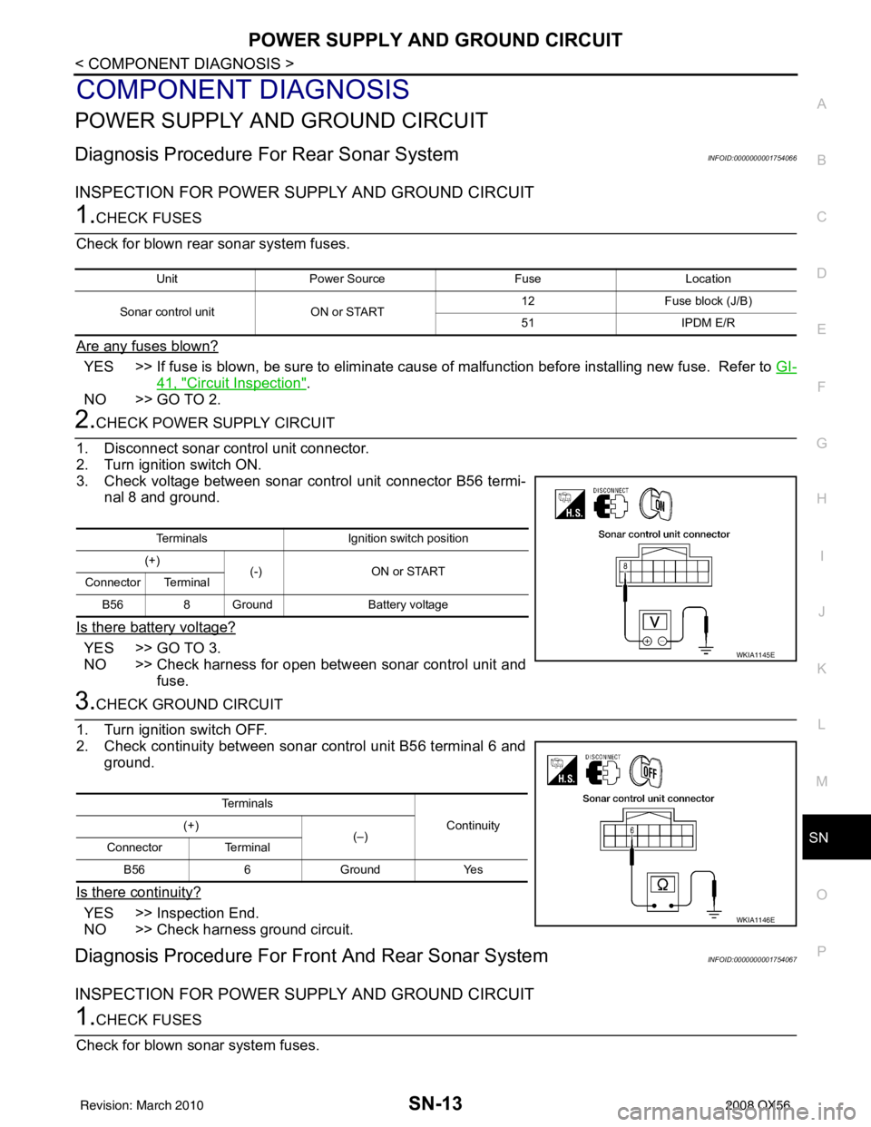
INSPECTION FOR POWER SUPPLY AND GROUND CIRCUIT
1.CHECK FUSES
Check for blown rear sonar system fuses.
Are any fuses blown?
YES >> If fuse is blown, be sure to eliminate cause of malfunction before installing new fuse. Refer to GI-
41, "Circuit Inspection".
NO >> GO TO 2.
2.CHECK POWER SUPPLY CIRCUIT
1. Disconnect sonar control unit connector.
2. Turn ignition switch ON.
3. Check voltage between sonar control unit connector B56 termi- nal 8 and ground.
Is there battery voltage?
YES >> GO TO 3.
NO >> Check harness for open between sonar control unit and fuse.
3.CHECK GROUND CIRCUIT
1. Turn ignition switch OFF.
2. Check continuity between sonar control unit B56 terminal 6 and ground.
Is there continuity?
YES >> Inspection End.
NO >> Check harness ground circuit.
Diagnosis Procedure For Fron t And Rear Sonar SystemINFOID:0000000001754067
INSPECTION FOR POWER SUPPLY AND GROUND CIRCUIT
1.CHECK FUSES
Check for blown sonar system fuses.
Unit Power Source FuseLocation
Sonar control unit ON or START 12
Fuse block (J/B)
51 IPDM E/R
Terminals Ignition switch position
(+) (-) ON or START
Connector Terminal
B56 8 Ground Battery voltage
WKIA1145E
Te r m i n a l s
Continuity
(+)
(–)
Connector Terminal
B56 6 Ground Yes
WKIA1146E
Revision: March 2010 2008 QX56
Page 3339 of 4083

SN-14
< COMPONENT DIAGNOSIS >
POWER SUPPLY AND GROUND CIRCUIT
Are any fuses blown?
YES >> If fuse is blown, be sure to eliminate cause of malfunction before installing new fuse. Refer to GI-
41, "Circuit Inspection".
NO >> GO TO 2.
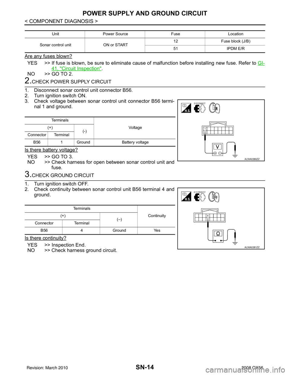
2.CHECK POWER SUPPLY CIRCUIT
1. Disconnect sonar control unit connector B56.
2. Turn ignition switch ON.
3. Check voltage between sonar control unit connector B56 termi- nal 1 and ground.
Is there battery voltage?
YES >> GO TO 3.
NO >> Check harness for open between sonar control unit and fuse.
3.CHECK GROUND CIRCUIT
1. Turn ignition switch OFF.
2. Check continuity between sonar control unit B56 terminal 4 and ground.
Is there continuity?
YES >> Inspection End.
NO >> Check harness ground circuit.
Unit Power Source FuseLocation
Sonar control unit ON or START 12
Fuse block (J/B)
51 IPDM E/R
Te r m i n a l s
Vo l ta g e
(+)
(-)
Connector Terminal
B56 1 Ground Battery voltage
ALNIA0380ZZ
Te r m i n a l s
Continuity
(+)
(–)
Connector Terminal
B56 4Ground Yes
ALNIA0381ZZ
Revision: March 2010 2008 QX56
Page 3411 of 4083

ON BOARD DIAGNOSTIC (OBD) SYSTEMSRC-13
< FUNCTION DIAGNOSIS >
C
DE
F
G
I
J
K L
M A
B
SRC
N
O P
ON BOARD DIAGNOSTIC (OBD) SYSTEM
Trouble Diagnosis IntroductionINFOID:0000000001735298
CAUTION:
• Do not use electrical test equipment on any circui t related to the SRS unless instructed to do so in
this Service Manual. SRS wiring harnesses can be id entified by yellow and/or orange harness con-
nectors.
• Do not attempt to repair, splice or modify SRS wiring harnesses. If a harness is damaged, replace it
with a new one.
• Keep ground connections clean.
DIAGNOSIS FUNCTION
The SRS self-diagnosis results can be read by usi ng “AIR BAG” warning lamp and/or CONSULT-III.
The User mode is exclusively prepared for the customer (driver). This mode warns the driver of a system mal-
function through the operation of the “AIR BAG” warning lamp.
The Diagnosis mode allows the technician to locate and inspect the malfunctioning part.
The mode applications for the “AIR BAG” warning lamp and CONSULT-III are as follows:
HOW TO PERFORM TROUBLE DIAGNOSES FOR QUICK AND ACCURATE REPAIR
A good understanding of the malfunction conditions can make troubleshooting faster and more accurate.
In general, each customer feels differently about a malf unction. It is important to fully understand the symp-
toms or conditions for a customer complaint.
Information From Customer
WHAT - Vehicle model
WHEN - Date, Frequencies
WHERE - Road conditions
HOW - Operating conditions, Symptoms
Preliminary Check
Check that the following parts are in good order.
•Battery
•Fuse
• System component-to-harness connections
SRS Operation CheckINFOID:0000000001735299
DIAGNOSTIC PROCEDURE 1
Checking SRS Operation Using “AIR BAG” Warning Lamp—User Mode
1. Turn the ignition switch from OFF to ON, and check that the air bag warning lamp blinks.
2. Compare the SRS air bag warning lamp blinking pattern with the examples.
User mode Diagnosis mode Display type
“AIR BAG” warning lamp XXON-OFF operation
CONSULT-III —XMonitoring
BF-1845D
Revision: March 2010 2008 QX56
Page 3488 of 4083

SRC-90
< SYMPTOM DIAGNOSIS >
SRS AIR BAG SYSTEM
SYMPTOM DIAGNOSIS
SRS AIR BAG SYSTEM
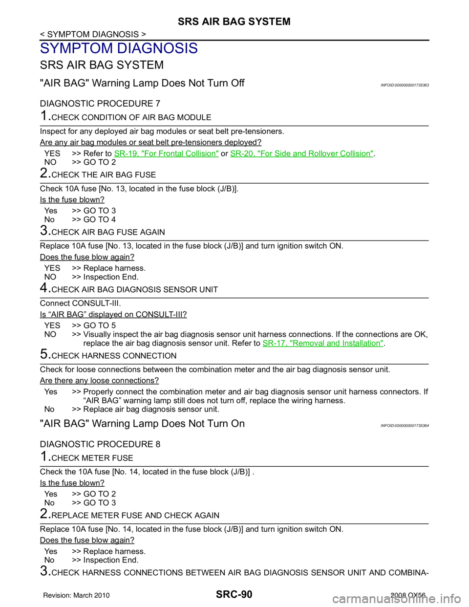
"AIR BAG" Warning Lamp Does Not Turn OffINFOID:0000000001735363
DIAGNOSTIC PROCEDURE 7
1.CHECK CONDITION OF AIR BAG MODULE
Inspect for any deployed air bag modules or seat belt pre-tensioners.
Are any air bag modules or s eat belt pre-tensioners deployed?
YES >> Refer to SR-19, "For Frontal Collision" or SR-20, "For Side and Rollover Collision".
NO >> GO TO 2
2.CHECK THE AIR BAG FUSE
Check 10A fuse [No. 13, locat ed in the fuse block (J/B)].
Is the fuse blown?
Ye s > > G O T O 3
No >> GO TO 4
3.CHECK AIR BAG FUSE AGAIN
Replace 10A fuse [No. 13, located in the fu se block (J/B)] and turn ignition switch ON.
Does the fuse blow again?
YES >> Replace harness.
NO >> Inspection End.
4.CHECK AIR BAG DIAGNOSIS SENSOR UNIT
Connect CONSULT-III.
Is
“AIR BAG” displayed on CONSULT-III?
YES >> GO TO 5
NO >> Visually inspect the air bag diagnosis sensor unit harness connections. If the connections are OK,
replace the air bag diagnosis sensor unit. Refer to SR-17, "
Removal and Installation".
5.CHECK HARNESS CONNECTION
Check for loose connections between the combination meter and the air bag diagnosis sensor unit.
Are there any loose connections?
Yes >> Properly connect the combination meter and air bag diagnosis sensor unit harness connectors. If
“AIR BAG” warning lamp still does not turn off, replace the wiring harness.
No >> Replace air bag diagnosis sensor unit.
"AIR BAG" Warning La mp Does Not Turn OnINFOID:0000000001735364
DIAGNOSTIC PROCEDURE 8
1.CHECK METER FUSE
Check the 10A fuse [No. 14, located in the fuse block (J/B)] .
Is the fuse blown?
Ye s > > G O T O 2
No >> GO TO 3
2.REPLACE METER FUSE AND CHECK AGAIN
Replace 10A fuse [No. 14, located in the fu se block (J/B)] and turn ignition switch ON.
Does the fuse blow again?
Yes >> Replace harness.
No >> Inspection End.
3.CHECK HARNESS CONNECTIONS BET WEEN AIR BAG DIAGNOSIS SENSOR UNIT AND COMBINA-
Revision: March 2010 2008 QX56
Page 3490 of 4083

SRC-92
< SYMPTOM DIAGNOSIS >
PASSENGER SEAT BELT WARNING SYSTEM
PASSENGER SEAT BELT WARNING SYSTEM
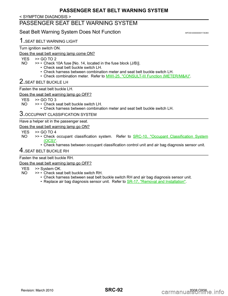
Seat Belt Warning System Does Not FunctionINFOID:0000000001735365
1.SEAT BELT WARNING LIGHT
Turn ignition switch ON.
Does the seat belt warning lamp come ON?
YES >> GO TO 2
NO >> • Check 10A fuse [No. 14, located in the fuse block (J/B)]. • Check seat belt buckle switch LH.
• Check harness between combination meter and seat belt buckle switch LH.
• Check combination meter. Refer to MWI-25, "
CONSULT-III Function (METER/M&A)".
2.SEAT BELT BUCKLE LH
Fasten the seat belt buckle LH.
Does the seat belt warning lamp go OFF?
YES >> GO TO 3
NO >> • Check seat belt buckle switch LH. • Check harness between combination meter and seat belt buckle switch LH.
3.OCCUPANT CLASSIFICATION SYSTEM
Have a helper sit in the passenger seat.
Does the seat belt warning lamp go ON?
YES >> GO TO 4
NO >> • Check occupant classification system. Refer to SRC-10, "
Occupant Classification System
(OCS)".
• Check harness between occupant classification control unit and air bag diagnosis sensor unit.
4.SEAT BELT BUCKLE RH
Fasten the seat belt buckle RH.
Does the seat belt warning lamp go OFF?
YES >> System OK.
NO >> • Check seat belt buckle switch RH. • Check harness between seat belt buckle switch RH and air bag diagnosis sensor unit.
• Replace air bag diagnosis sensor unit. Refer to SR-17, "
Removal and Installation".
Revision: March 2010 2008 QX56