Page 2796 of 4083

PG
POWER SUPPLY ROUTING CIRCUITPG-29
< COMPONENT DIAGNOSIS >
C
DE
F
G H
I
J
K L
B A
O P
N
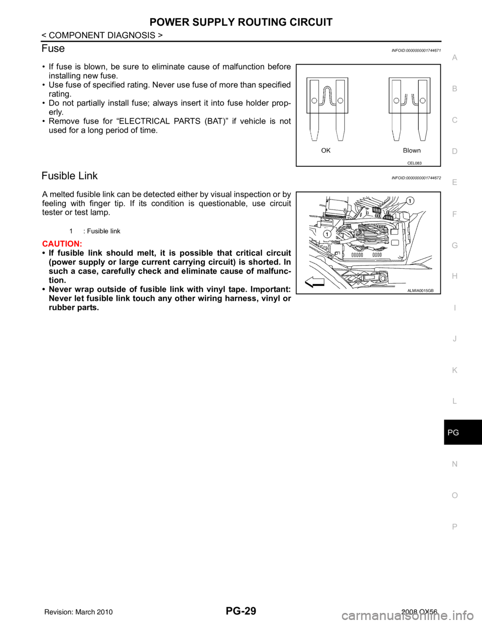
FuseINFOID:0000000001744671
• If fuse is blown, be sure to eliminate cause of malfunction before
installing new fuse.
• Use fuse of specified rating. Never use fuse of more than specified
rating.
• Do not partially install fuse; always insert it into fuse holder prop- erly.
• Remove fuse for “ELECTRICAL PARTS (BAT)” if vehicle is not used for a long period of time.
Fusible LinkINFOID:0000000001744672
A melted fusible link can be detected either by visual inspection or by
feeling with finger tip. If its condition is questionable, use circuit
tester or test lamp.
CAUTION:
• If fusible link should melt, it is possible that critical circuit
(power supply or large current carrying circuit) is shorted. In
such a case, carefully check and eliminate cause of malfunc-
tion.
• Never wrap outside of fusible li nk with vinyl tape. Important:
Never let fusible link touch any other wiring harness, vinyl or
rubber parts.
CEL083
1 : Fusible link
ALMIA0015GB
Revision: March 2010 2008 QX56
Page 2808 of 4083
PG
HARNESSPG-41
< COMPONENT DIAGNOSIS >
C
DE
F
G H
I
J
K L
B A
O P
N
MAIN HARNESS
AWMIA0111GB
G4 M1 W/16 : To R1
G4 M84 W/16 : To B101
F4 M2 W/12 : To R2 B3 M87 B/5 : Rear power vent window relay (open)
G2 M3 W/8 : Fuse block (J/B) B3 M89 B/5 : Rear power vent window relay (close)
G2 M4 W/16 : Fuse block (J/B) B3 M91 W/16 : To E26
Revision: March 2010 2008 QX56
Page 2809 of 4083

PG-42
< COMPONENT DIAGNOSIS >
HARNESS
A3 M6 W/10 : To E10A2 M92 B/6 : Power liftgate switch
A2 M7 B/5 : Passenger select unlock relay D1 M93 W/24 : Display unit
A3 M8 W/16 : To D2 A2 M95 W/6 : Rear power vent window switch
A2 M9 BR/24 : To D1 A2 M96 BR/6 : Pedal adjusting switch
A3 M10 Y/4 : To E29 C2 M98 W/16 : A/C and AV switch assembly
A3 M11 B/1 : Parking brake switch C3 M99 BR/2 : Foot lamp LH
C3 M12 GR/6 : Key switch and ignition knob switch F4 M100 BR/2 : Foot lamp RH
D3 M13 BR/2 : Front passenger air bag OFF indicator F4 M101 Y/2 : Driver air bag module
B3 M15 W/4 : Steering lock solenoid F4 M102 GR/8 : Combination switch (spiral cable)
A2 M16 GR/6 : ADP steering switch F4 M103 Y/2 : Driver air bag module
B2 M17 W/8 : Steering angle sensor E3 M104 W/4 : Aux jack
C2 M18 W/40 : BCM (body control module) F2 M105 Y/2 : Front passenger air bag module
C2 M19 W/15 : BCM (body control module) F2 M106 O/2 : Front passenger air bag module
C2 M20 B/15 : BCM (body control module) F3 M107 B/5 : Front blower relay
C3 M22 W/16 : Data link connector D5 M108 B/6 : Yaw rate/ side/ decel G sensor
B1 M23 W/12 : Combination meter A1 M109 BR/2 : Front tweeter LH
C1 M24 W/40 : Combination meter D2 M110 BR/2 : Center speaker
F2 M25 B/4 : Remote keyless entry receiver F2 M111 BR/2 : Front tweeter LH
B2 M26 W/6 : Ignition switch C2M112 BR/14 : BO SE speaker amp.
A2 M27 B/2 : Diode-3 C2 M113 BR/23 : BOSE speaker amp.
B2 M28 W/16 : Combination switch B3 M114 W/2 : Heated steering wheel
B2 M29 Y/6 : Combination switch (spiral cable) A2 M116 GR/8 : Sonar system OFF switch
B3 M30 GR/8 : Combination switch (spiral cable) B1 M118 BR/2 : Front sonar buzzer
G4 M31 SMJ : To E152 F2 M120 W/4 : Remote keyless entry receiver
C3 M32 W/4 : In-vehicle sensor F4 M122 W/4 : Variable blower control (front)
B3 M33 W/32 : Automatic drive position control unit C3 M123 W/2 : Tire pressure warning check connector
B3 M34 W/16 : Automatic drive position control unit D2 M124 GR/3 : AV control unit
C5 M35 Y/28 : Air bag diagnosis sensor unit D2 M125 B/1 : Satellite radio antenna
G4 M36 SMJ : To B149 C3 M129 V/1 : Satellite radio tuner
G3 M37 B/1 : Fuse block (J/B) D2 M139 B/2 : Diode-1
G3 M38 B/2 : Fuse block (J/B) D1 M140 B/2 : Diode-2
D3 M39 W/8 : Fuse block (J/B) C2 M141 GR/8 : 4WD shift switch
A3 M40 SMJ : To B69 E1 M142 B/6 : Mode door motor (front)
D2 M42 W/20 : AV control unit E3 M143 B/6 : Air mix door motor (passenger)
D2 M43 W/12 : AV control unit C1 M144 B/6 : Defroster door motor
D2 M44 W/32 : AV control unit E3 M146 GR/2 : Intake sensor
D3 M45 W/40 : AV control unit D3 M147B/6 : Air mix doo r motor (driver)
D2 M46 W/32 : AV control unit D2 M148 W/4 : Headlamp aiming switch
D2 M49 L/26 : A/C auto AMP D3 M149 W/4 : Clock
D2 M50 B/26 : A/C auto AMP B1 M150 W/2 : Ignition keyhole illumination
B3 M51 L/4 : Trailer tow relay 1 G4 M157 W/20 : To B161
B2 M52 W/2 : Combination switch (spiral cable) A3 M158 W/10 : To D3
D3 M53 B/3 : Front power socket LH Console sub-harness
E3 M54 B/3 : Front power socket RH (for cigarette
lighter) D4 M201 W/16 : To M56
D2 M55 W/4 : Hazard switch D4 M202 BR/24 : To M64
Revision: March 2010 2008 QX56
Page 2810 of 4083

PG
HARNESSPG-43
< COMPONENT DIAGNOSIS >
C
DE
F
G H
I
J
K L
B A
O P
N
D4 M56 W/16 : To M201
D4 M203 W/12 : A/T shift selector
A3 M57 — : Body ground D5 M205 W/32 : DVD player
F2 M58 B/6 : Intake door motor D5 M207 BR/20 : Console power socket
F3 M59 BR/2 : Glove box lamp C4 M208 BR/20 : To M69
G3 M60 W/6 : Fuse block (J/B) C5 M209 W/2: Inside key antenna 2 (rear of center
console)
C3 M61 — : Body ground C4 M210 GR/2: Inside key antenna 3 (front of center
console)
F4 M62 B/2 : Front blower motor C4 M212 W/6 : Rear heated seat switch LH
D4 M63 BR/20 : To M251 C4 M213 BR/6 : Rear heated seat switch RH
D4 M64 BR/24 : To M202 Console switch sub-harness
F2 M65 W/4 : To M301 D4 M251 BR/20 : To M63
G3 M66 BR/1 : To E33 D4 M252 BR/6 : Front heated seat switch RH
C3 M69 BR/20 : To M208 C4 M253 GR/6 : VDC OFF switch
A2 M70 W/40 : Intelligent key unit C3 M255 W/6 : Front heated seat switch LH
A2 M71 L/4 : Heated steering relay C4 M256 B/2 : A/T shift selector
D3 M73 BR/6 : Back-up lamp relay C4 M260 W/6 : Heated steering wheel switch
G3 M74 BR/24 : To D102 Optical sensor sub-harness
G3 M75 W/10 : To D101 F1 M301 W/4 : To M65
A3 M76 W/6 : Electric brake (pre-wiring) D1 M302 B/4 : Optical sensor
E2 M77 Y/4 : Front passenger air bag module
(service replacement) Antenna amp. sub-harness
G3 M78 BR/2 : To M550 D3 M550 BR/2 : To M78
E2 M79 — : Body ground D3 M551 BR/3 : To M601
C1 M80 B/2 : Resistor D3 M601 GR/3 : To M551
E3 M81 GR/10 : Shift lock control unit D3 M602 W/2 : Antenna amp.
A3 M82 GR/2 : Circuit breaker-2
Revision: March 2010 2008 QX56
Page 2837 of 4083
PG-70
< COMPONENT DIAGNOSIS >
FUSE BLOCK - JUNCTION BOX (J/B)
FUSE BLOCK - JUNCTION BOX (J/B)
Terminal ArrangementINFOID:0000000001744678
AWMIA0898GB
Revision: March 20102008 QX56
Page 2838 of 4083
PG
FUSE, FUSIBLE LINK AND RELAY BOXPG-71
< COMPONENT DIAGNOSIS >
C
DE
F
G H
I
J
K L
B A
O P
N
FUSE, FUSIBLE LINK AND RELAY BOX
Terminal ArrangementINFOID:0000000001744679
FUSE AND FUSIBLE LINK BOX
AAMIA0217GB
Revision: March 2010
2008 QX56
Page 2839 of 4083
PG-72
< COMPONENT DIAGNOSIS >
FUSE, FUSIBLE LINK AND RELAY BOX
FUSE AND RELAY BOX
ALMIA0223GB
Revision: March 20102008 QX56
Page 2989 of 4083

INSPECTION AND ADJUSTMENTRF-5
< BASIC INSPECTION >
C
DE
F
G H
I
J
L
M A
B
RF
N
O P
INSPECTION AND ADJUSTMENT
ADDITIONAL SERVICE WHEN REPLACING CONTROL UNIT
ADDITIONAL SERVICE WHEN REPL ACING CONTROL UNIT : Description
INFOID:0000000001731919
MEMORY RESET PROCEDURE
1. Please observe the following instructi ons at confirming the sunroof operation.
NOTE:
Do not disconnect the electronic power while the sunroof is operating or within 5 seconds after the sunroof
stops. (to wipe-out the memory of lid position and operating friction.)
2. Initialization of system should be conducted after the following conditions.
• When the sunroof motor is changed.
• When the sunroof does not operate normally. (Incomplete initialization conditions)
ADDITIONAL SERVICE WHEN REPLACING CONTROL UNIT : Special Repair Re-
quirement
INFOID:0000000001731920
INITIALIZATION PROCEDURE
If the sunroof does not close or open automatically, us e the following procedure to return sunroof operation to
normal.
1. Turn ignition switch ON.
2. Push and hold the sunroof tilt switch in the forw ard (DOWN) position until the sunroof is fully closed.
3. After the sunroof has closed all the way, push and hold the tilt switch forward (DOWN) again for more than 2 seconds to re-learn motor position.
4. Initialization is complete if the sunroof operates normally.
BASIC INSPECTION
BASIC INSPECTION : Special Repair RequirementINFOID:0000000001731921
BASIC INSPECTION
1.INSPECTION START
1. Check the service history.
2. Check the following parts.
• Fuse/circuit breaker blown.
• Poor connection, open or short circuit of harness connector.
• Battery voltage.
Is the inspection result normal?
YES >> Inspection End.
NO >> Repair or replace the malfunctioning parts.
Revision: March 2010 2008 QX56