2008 INFINITI QX56 fuse
[x] Cancel search: fusePage 1938 of 4083

EXL-10
< FUNCTION DIAGNOSIS >
DAYTIME LIGHT SYSTEM
Component Description
INFOID:0000000001547101
After starting the engine with the parking brake released and the lighting switch in the OFF or 1ST position, the
headlamp high beam automatically turns on at a reduced intensity. With the lighting switch in the 2nd position
or with autolamps ON, the headlamps function the same as conventional light systems.
OPERATION
The BCM monitors inputs from the parking brake switch and the combination switch to determine when to acti-
vate the daytime light system. The BCM sends a dayti me light request to the IPDM E/R via the CAN commu-
nication lines. The IPDM E/R grounds the daytime light relay which in turn, provides power to the ground side
of the LH high beam lamp. Power flows backward through the LH high beam lamp to the IPDM E/R, through
the high beam fuses, through the RH high beam lamp circuit to the RH high beam lamp and on to ground. The
high beam lamps are wired in series which causes them to illuminate at a reduced intensity.
1. IPDM E/R E119, E122, E123, E124 2. Parking brake switch M11 3. BCM M18, M20 (view with instrument
panel removed)
4. Daytime running light relay E103 5. Combination switch M28 6. Combination meter M24
Revision: March 2010 2008 QX56
Page 1956 of 4083
EXL-28
< COMPONENT DIAGNOSIS >
HEADLAMP (HI) CIRCUIT
HEADLAMP (HI) CIRCUIT
DescriptionINFOID:0000000001547125
The IPDM E/R (intelligent power distribution module engine room) controls the headlamp high relay based on
inputs from the BCM via the CAN communication lines. When the headlamp high relay is energized, power
flows through fuses 34 and 35, located in the IPDM E/R. Power then flows to the front combination lamps to
the headlamp high beam.
Component Function CheckINFOID:0000000001547126
1.CHECK HEADLAMP (HI) OPERATION
WITHOUT CONTULT-III
1. Start IPDM E/R auto active test. Refer to PCS-12, "
Diagnosis Description".
2. Check that the headlamp switches to the high beam. NOTE:
HI/LO is repeated 1 second each when usi ng the IPDM E/R auto active test.
CONSULT-III
1. Select "EXTERNAL LAMP" of IPDM E/R active test item.
2. With the test item operating, check that the headlamp switches to high beam.
Does the headlamp switch to high beam?
YES >> Headlamp (HI) circuit is normal.
NO >> Refer to EXL-28, "
Diagnosis Procedure".
Diagnosis ProcedureINFOID:0000000001547127
1.CHECK HEADLAMP (HI) FUSES
1. Turn the ignition switch OFF.
2. Check that the following fuses are not open.
Is the fuse open?
YES >> Repair the harness and replace the fuse.
NO >> GO TO 2
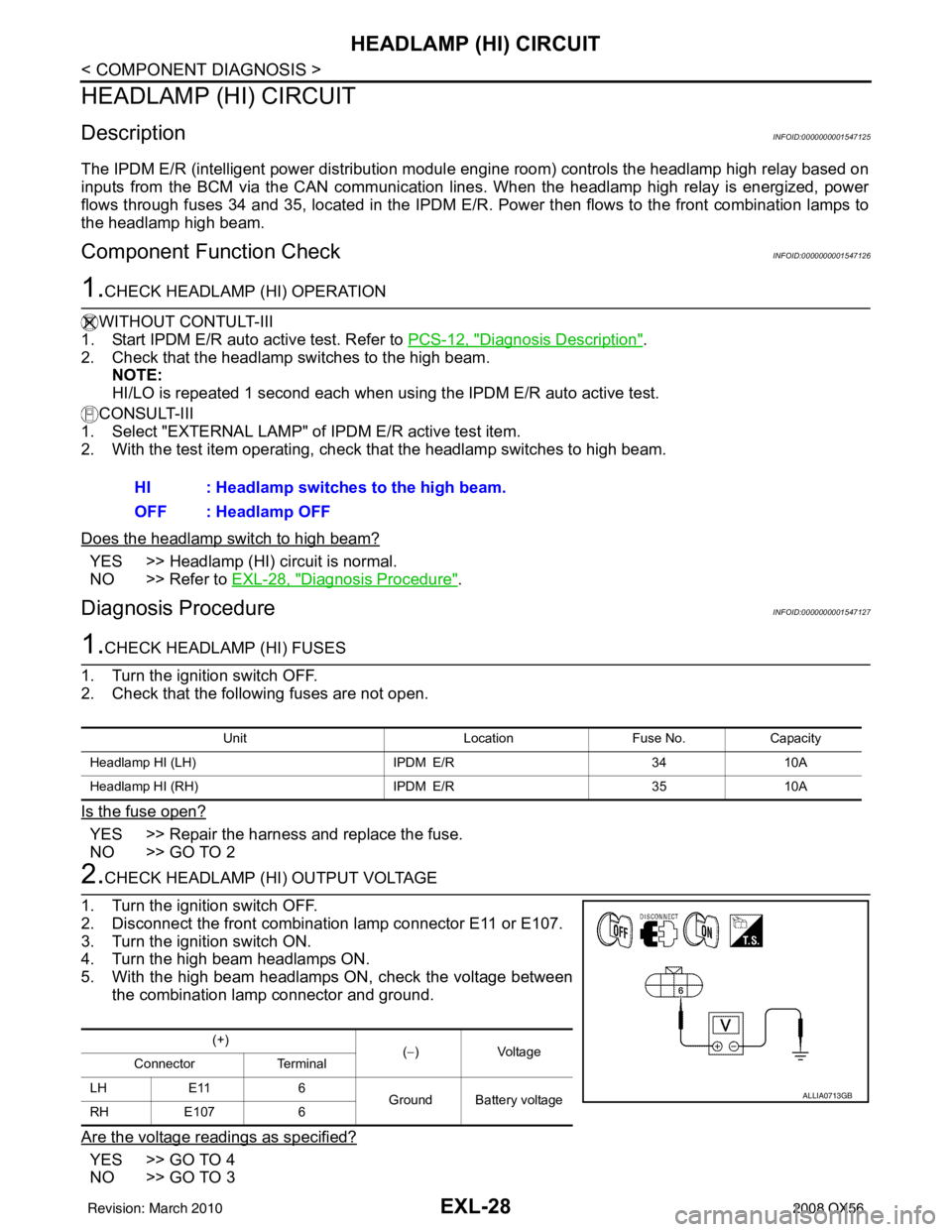
2.CHECK HEADLAMP (HI) OUTPUT VOLTAGE
1. Turn the ignition switch OFF.
2. Disconnect the front combination lamp connector E11 or E107.
3. Turn the ignition switch ON.
4. Turn the high beam headlamps ON.
5. With the high beam headlamps ON, check the voltage between the combination lamp connector and ground.
Are the voltage readings as specified?
YES >> GO TO 4
NO >> GO TO 3 HI : Headlamp switches to the high beam.
OFF : Headlamp OFF
Unit
LocationFuse No.Capacity
Headlamp HI (LH) IPDM E/R3410A
Headlamp HI (RH) IPDM E/R3510A
(+)
(−)Voltage
Connector Terminal
LH E11 6
Ground Battery voltage
RH E107 6
ALLIA0713GB
Revision: March 2010 2008 QX56
Page 1958 of 4083
EXL-30
< COMPONENT DIAGNOSIS >
HEADLAMP (LO) CIRCUIT
HEADLAMP (LO) CIRCUIT
DescriptionINFOID:0000000001547128
The IPDM E/R (intelligent power distribution module engine room) controls the headlamp low relay based on
inputs from the BCM via the CAN communication lines. When the headlamp low relay is energized, power
flows through fuses 40 and 41, located in the IPDM E/R. Power then flows to the front combination lamps to
the headlamp low beam.
Component Function CheckINFOID:0000000001547129
1.CHECK HEADLAMP (LO) OPERATION
WITHOUT CONSULT-III
1. Start IPDM E/R auto active test. Refer to PCS-12, "
Diagnosis Description".
2. Check that the headlamp is turned ON. NOTE:
HI/LO is repeated 1 second each when usi ng the IPDM E/R auto active test.
CONSULT-III
1. Select "EXTERNAL LAMP" of IPDM E/R active test item.
2. With the test items operating, check that the headlamp is turned ON.
Is the headlamp turned ON?
YES >> Headlamp (LO) is normal.
NO >> Refer to EXL-30, "
Diagnosis Procedure".
Diagnosis ProcedureINFOID:0000000001547130
1.CHECK HEADLAMP (LO) FUSES
1. Turn the ignition switch OFF.
2. Check that the following fuses are not open.
Is the fuse open?
YES >> Repair the harness and replace the fuse.
NO >> GO TO 2
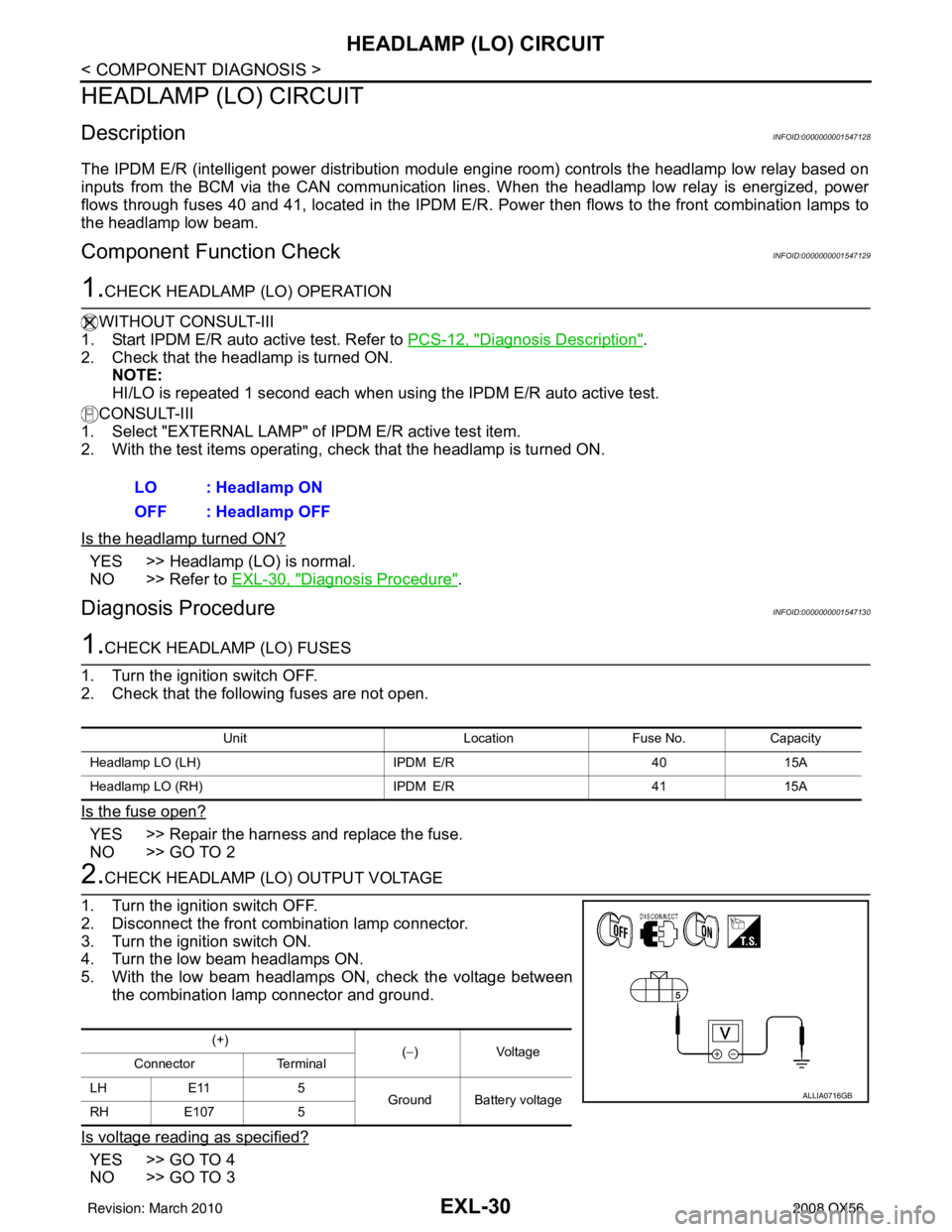
2.CHECK HEADLAMP (LO) OUTPUT VOLTAGE
1. Turn the ignition switch OFF.
2. Disconnect the front combination lamp connector.
3. Turn the ignition switch ON.
4. Turn the low beam headlamps ON.
5. With the low beam headlamps ON, check the voltage between the combination lamp connector and ground.
Is voltage reading as specified?
YES >> GO TO 4
NO >> GO TO 3 LO : Headlamp ON
OFF : Headlamp OFF
Unit
LocationFuse No.Capacity
Headlamp LO (LH) IPDM E/R4015A
Headlamp LO (RH) IPDM E/R4115A
(+)
(−)Voltage
Connector Terminal
LH E11 5 Ground Battery voltage
RH E107 5
ALLIA0716GB
Revision: March 2010 2008 QX56
Page 1960 of 4083
EXL-32
< COMPONENT DIAGNOSIS >
FRONT FOG LAMP CIRCUIT
FRONT FOG LAMP CIRCUIT
DescriptionINFOID:0000000001547131
The IPDM E/R (intelligent power distribution module engine room) controls the front fog lamp relay based on
inputs from the BCM via the CAN communication lines. When the front fog lamp relay is energized, power
flows from the front fog lamp relay in the IPDM E/R to the front fog lamps.
Component Function CheckINFOID:0000000001547132
1.CHECK FRONT FOG LAMP OPERATION
WITHOUT CONSULT-III
1. Activate IPDM E/R auto active test. Refer to PCS-12, "
Diagnosis Description".
2. Check that the front fog lamp is turned ON.
CONSULT-III
1. Select "EXTERNAL LAMP" of IPDM E/R active test item.
2. With operating the test items, Check that the front fog lamp is turned ON.
Is the front fog lamp turned ON?
YES >> Front fog lamp circuit is normal.
NO >> Refer to EXL-32, "
Diagnosis Procedure".
Diagnosis ProcedureINFOID:0000000001547133
1.CHECK FRONT FOG LAMP FUSE
1. Turn the ignition switch OFF.
2. Check that the following fuses are not open.
Is the fuse open?
YES >> Repair the harness and replace the fuse.
NO >> GO TO 2
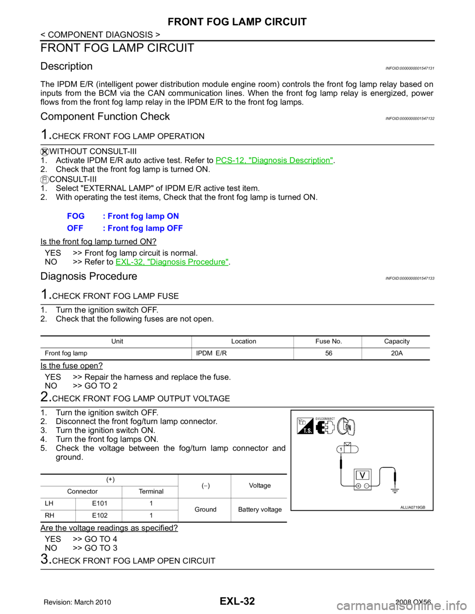
2.CHECK FRONT FOG LAMP OUTPUT VOLTAGE
1. Turn the ignition switch OFF.
2. Disconnect the front fog/turn lamp connector.
3. Turn the ignition switch ON.
4. Turn the front fog lamps ON.
5. Check the voltage between the fog/turn lamp connector and ground.
Are the voltage readings as specified?
YES >> GO TO 4
NO >> GO TO 3
3.CHECK FRONT FOG LAMP OPEN CIRCUIT FOG : Front fog lamp ON
OFF : Front fog lamp OFF
Unit
LocationFuse No.Capacity
Front fog lamp IPDM E/R5620A
(+)
(−)V olt a g e
Connector Terminal
LH E101 1
Ground Battery voltage
RH E102 1
ALLIA0719GB
Revision: March 2010 2008 QX56
Page 1962 of 4083
EXL-34
< COMPONENT DIAGNOSIS >
PARKING LAMP CIRCUIT
PARKING LAMP CIRCUIT
DescriptionINFOID:0000000001547134
The IPDM E/R (intelligent power distribution module engine room) controls the tail lamp relay based on inputs
from the BCM via the CAN communication lines. When the tail lamp relay is energized, power flows through
fuse 37, located in the IPDM E/R. Power then flows to the front and rear combination lamps.
Component Function CheckINFOID:0000000001547135
1.CHECK PARKING LAMP OPERATION
WITHOUT CONSULT-III
1. Activate IPDM E/R auto active test. Refer to PCS-12, "
Diagnosis Description".
2. Check that the parking lamp is turned ON.
CONSULT-III
1. Select "EXTERNAL LAMP" of IPDM E/R active test item.
2. With operating the test items, check that the parking lamp is turned ON.
Is the parking lamp turned ON?
YES >> Parking lamp circuit is normal.
NO >> Refer to EXL-34, "
Diagnosis Procedure".
Diagnosis ProcedureINFOID:0000000001547136
1.CHECK PARKING LAMP FUSES
1. Turn the ignition switch OFF.
2. Check that the following fuses are not open.
Is the fuse open?
YES >> Repair the harness and replace the fuse.
NO >> GO TO 2
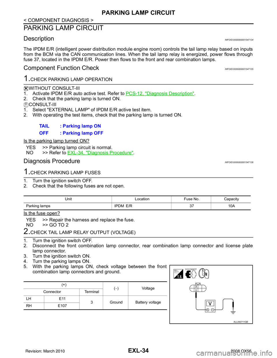
2.CHECK TAIL LAMP RELAY OUTPUT (VOLTAGE)
1. Turn the ignition switch OFF.
2. Disconnect the front combination lamp connector, rear combination lamp connector and license plate
lamp connector.
3. Turn the ignition switch ON.
4. Turn the parking lamps ON.
5. With the parking lamps ON, check voltage between the front combination lamp connectors and ground.TAIL : Parking lamp ON
OFF : Parking lamp OFF
Unit
LocationFuse No.Capacity
Parking lamps IPDM E/R3710A
(+)
(−)Voltage
Connector Terminal
LH E11
3 Ground Battery voltage
RH E107
ALLIA0711GB
Revision: March 2010 2008 QX56
Page 2029 of 4083
EXTERIOR LIGHTING SYSTEM SYMPTOMSEXL-101
< SYMPTOM DIAGNOSIS >
C
DE
F
G H
I
J
K
M A
B
EXL
N
O P
SYMPTOM DIAGNOSIS
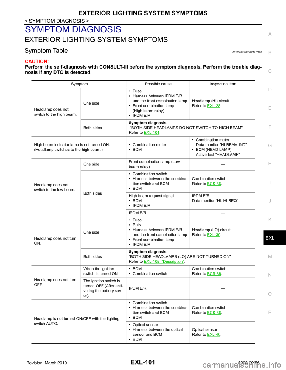
EXTERIOR LIGHTING SYSTEM SYMPTOMS
Symptom TableINFOID:0000000001547153
CAUTION:
Perform the self-diagnosis with CONS ULT-III before the symptom diagnosis. Perform the trouble diag-
nosis if any DTC is detected.
Symptom Possible causeInspection item
Headlamp does not
switch to the high beam. One side•Fuse
• Harness between IPDM E/R
and the front combination lamp
• Front combination lamp
(High beam relay)
• IPDM E/R Headlamp (HI) circuit
Refer to
EXL-28
.
Both sides Symptom diagnosis
"BOTH SIDE HEADLAMPS DO NOT SWITCH TO HIGH BEAM"
Refer to EXL-104
.
High beam indicator lamp is not turned ON.
(Headlamp switches to the high beam.) • Combination meter
•BCM• Combination meter.
Data monitor "HI-BEAM IND"
• BCM (HEAD LAMP) Active test "HEADLAMP"
Headlamp does not
switch to the low beam. One side
Front combination lamp (Low
beam relay)
—
Both sides • Combination switch
• Harness between the combina-
tion switch and BCM
•BCM Combination switch
Refer to
BCS-36
.
High beam request signal
•BCM
• IPDM E/R IPDM E/R
Data monitor "HL HI REQ"
IPDM E/R —
Headlamp does not turn
ON. One side•Fuse
•Bulb
• Harness between IPDM E/R
and the front combination lamp
• Front combination lamp
• IPDM E/R Headlamp (LO) circuit
Refer to
EXL-30
.
Both sides Symptom diagnosis
"BOTH SIDE HEADLAMPS (LO) ARE NOT TURNED ON"
Refer to EXL-105, "
Description".
Headlamp does not turn
OFF. When the ignition
switch is turned ON
•BCM
• Combination switch Combination switch
Refer to
BCS-36
.
The ignition switch is
turned OFF (After acti-
vating the battery sav-
er). IPDM E/R
—
Headlamp is not turned ON/OFF with the lighting
switch AUTO. • Combination switch
• Harness between the combina-
tion switch and BCM
•BCM Combination switch
Refer to
BCS-36
.
• Optical sensor
• Harness between the optical sensor and BCM
•BCM Optical sensor
Refer to
EXL-40
.
Revision: March 2010 2008 QX56
Page 2030 of 4083
EXL-102
< SYMPTOM DIAGNOSIS >
EXTERIOR LIGHTING SYSTEM SYMPTOMS
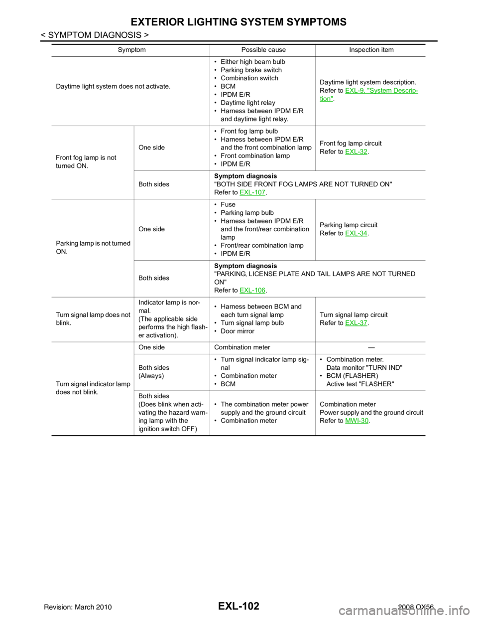
Daytime light system does not activate.• Either high beam bulb
• Parking brake switch
• Combination switch
•BCM
• IPDM E/R
• Daytime light relay
• Harness between IPDM E/R
and daytime light relay. Daytime light system description.
Refer to EXL-9, "System Descrip-
tion".
Front fog lamp is not
turned ON. One side
• Front fog lamp bulb
• Harness between IPDM E/R
and the front combination lamp
• Front combination lamp
• IPDM E/R Front fog lamp circuit
Refer to EXL-32
.
Both sides Symptom diagnosis
"BOTH SIDE FRONT FOG LAMPS ARE NOT TURNED ON"
Refer to
EXL-107
.
Parking lamp is not turned
ON. One side•Fuse
• Parking lamp bulb
• Harness between IPDM E/R
and the front/rear combination
lamp
• Front/rear combination lamp
• IPDM E/R Parking lamp
circuit
Refer to EXL-34
.
Both sides Symptom diagnosis
"PARKING, LICENSE PLATE AND TAIL LAMPS ARE NOT TURNED
ON"
Refer to
EXL-106
.
Turn signal lamp does not
blink. Indicator lamp is nor-
mal.
(The applicable side
performs the high flash-
er activation).• Harness between BCM and
each turn signal lamp
• Turn signal lamp bulb
• Door mirror Turn signal lamp circuit
Refer to EXL-37
.
Turn signal indicator lamp
does not blink. One side
Combination meter —
Both sides
(Always) • Turn signal indicator lamp sig-
nal
• Combination meter
•BCM • Combination meter.
Data monitor "TURN IND"
•BCM (FLASHER)
Active test "FLASHER"
Both sides
(Does blink when acti-
vating the hazard warn-
ing lamp with the
ignition switch OFF) • The combination meter power
supply and the ground circuit
• Combination meter Combination meter
Power supply and the ground circuit
Refer to MWI-30
.
Symptom
Possible causeInspection item
Revision: March 2010 2008 QX56
Page 2153 of 4083
HOW TO READ WIRING DIAGRAMSGI-11
< HOW TO USE THIS MANUAL >
C
DE
F
G H
I
J
K L
M B
GI
N
O P
DescriptionINFOID:0000000001539192
SWITCH POSITIONS
Switches are shown in wiring diagrams as if the vehicle is in the “normal” condition.
A vehicle is in the “normal” condition when:
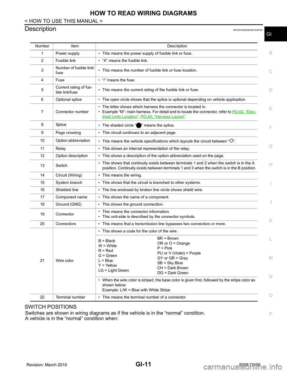
Number Item Description
1 Power supply • This means the power supply of fusible link or fuse.
2 Fusible link • “X” means the fusible link.
3 Number of fusible link/
fuse • This means the number of fusible link or fuse location.
4 Fuse • “/” means the fuse.
5 Current rating of fus-
ible link/fuse • This means the current rating of the fusible link or fuse.
6 Optional splice • The open circle shows that the splice is optional depending on vehicle application.
7 Connector number • The letter shows which harness the connector is located in.
• Example “M”: main harness. For detail and to locate the connector, refer to
PG-62, "
Elec-
trical Units Location", PG-40, "Harness Layout".
8Splice • The shaded circle “ ” means the splice.
9 Page crossing • This circuit continues to an adjacent page.
10 Option abbreviation • This means the vehicle specifications which layouts the circuit between “ ”.
11 Relay • This shows an internal representation of the relay.
12 Option description • This shows a description of the option abbreviation used on the page.
13 Switch • This shows that continuity exists between terminals 1 and 2 when the switch is in the A
position. Continuity exists between terminals 1 and 3 when the switch is in the B position.
14 Circuit (Wiring) • This means the wiring.
15 System branch • This shows that the circuit is branched to other systems.
16 Shielded line • The line enclosed by broken line circle shows shield wire.
17 Component name • This shows the name of a component.
18 Ground (GND) • This shows the ground connection.
19 Connector • This means the connector information.
• This unit-side is described by the connector symbols.
20 Connectors • This means that a transmission line bypasses two connectors or more.
21 Wire color • This shows a code for the color of the wire.
B = Black
W = White
R = Red
G = Green
L = Blue
Y = Yellow
LG = Light Green BR = Brown
OR or O = Orange
P = Pink
PU or V (Violet) = Purple
GY or GR = Gray
SB = Sky Blue
CH = Dark Brown
DG = Dark Green
• When the wire color is striped, the base color is given first, followed by the stripe color as shown below:
Example: L/W = Blue with White Stripe
22 Terminal number • This means the terminal number of a connector.
Revision: March 2010 2008 QX56