Page 3857 of 4083

HEATER & COOLING UNIT ASSEMBLYVTL-17
< ON-VEHICLE REPAIR >
C
DE
F
G H
J
K L
M A
B
VTL
N
O P
1. Move the two front seats to the rear most position on the seat track.
2. Disconnect the battery negative terminal and battery positive terminal.
3. Discharge the refrigerant from the A/C system. Refer to HA-20, "
HFC-134a (R-134a) Service Procedure".
4. Drain the coolant from the engine cooling system. Refer to CO-11, "
Changing Engine Coolant".
5. Disconnect the front heater hoses from the front heater core.
6. Disconnect the high/low pressure pipes from the front expansion valve.
7. Remove the instrument panel and console panel. Refer to IP-12, "
Removal and Installation".
8. Remove the steering column. Refer to ST-20, "
Removal and Installation".
9. Disconnect the instrument panel wire harness at t he RH and LH in-line connector brackets, and the fuse
block (J/B) electrical connectors. Refer to PG-9, "
Wiring Diagram — Battery Power Supply —".
10. Disconnect the steering member from each side of the vehicle body.
11. Remove the front heater and cooling unit assembly with it attached to the steering member, from the vehi- cle.
CAUTION:
Use care not to damage the seats and interior trim panels when removing the front heater and
cooling unit assembly with it at tached to the steering member.
12. Remove the front heater and cooling uni t assembly from the steering member.
Installation
Installation is in the reverse order of removal.
CAUTION:
• Replace the O-ring of the low-pressure pipe and high-pressure pipe with a new one, and apply com-
pressor oil to it when installing it.
• After charging the refrigerant, check for leaks.
NOTE:
• Fill the engine cooling system with the specified coolant mixture. Refer to CO-11, "
Changing Engine Cool-
ant".
• Recharge the A/C system. Refer to HA-20, "
HFC-134a (R-134a) Service Procedure".
REAR HEATER AND COOLING UNIT ASSEMBLY
Removal
1. Discharge the refrigerant from the A/C system. Refer to HA-20, "HFC-134a (R-134a) Service Procedure".
2. Drain the coolant from the engine cooling system. Refer to CO-11, "
Changing Engine Coolant".
3. Remove the luggage side finisher lower RH. Refer to INT-19, "
Removal and Installation".
4. Disconnect the rear heater core hoses from the rear heater core.
5. Disconnect the rear A/C pipes from the rear expansion valve.
6. Disconnect the following electrical connectors: • Rear blower motor
• Rear variable blower control
• Rear air mix door motor
7. Disconnect the ducts from the rear heater and cooling unit assembly.
8. Remove the rear heater and cooling unit assembly.
Installation
Installation is in the reverse order of removal.
CAUTION:
• Replace the O-ring of the low-pressure pipe and high-pressure pipe with a new one, and apply com- pressor oil to it when installing it.
• After charging the refrigerant, check for leaks.
NOTE:
• Fill the engine cooling system with the specified coolant mixture. Refer to CO-11, "
Changing Engine Cool-
ant".
• Recharge the A/C system. Refer to HA-20, "
HFC-134a (R-134a) Service Procedure".
Revision: March 2010 2008 QX56
Page 3872 of 4083
VTL-32
< ON-VEHICLE REPAIR >
DUCTS AND GRILLES
Grilles
ALIIA0067ZZ
1. Front pillar finisher (RH shown LH similar) 2. Side demister grille (RH shown LH
similar) 3. Rear roof console
4. Rear roof console grilles 5. Instrument panel 6. Side ventilator grille (LH)
7. Instrument side finisher (LH) 8. Ventilator grille (LH) 9. Ventilator grille (RH)
10. Cluster lid C 11. Instrument side finisher (RH) 12. Side ventilator grille (RH)
⇐ Front
Revision: March 2010 2008 QX56
Page 3873 of 4083

DUCTS AND GRILLESVTL-33
< ON-VEHICLE REPAIR >
C
DE
F
G H
J
K L
M A
B
VTL
N
O P
Removal and InstallationINFOID:0000000001516623
CENTER CONSOLE HEAT DUCT AND RE AR FINISHER ASSEMBLY GRILLE
Removal
The center console must be removed and disassembled to remove the heat duct and rear finisher assembly
grille. Refer to IP-20, "
Removal and Installation".
Installation
Installation is in the reverse order of removal.
DEFROSTER NOZZLE
Removal
1. Remove the instrument panel trim. Refer to IP-12, "Removal and Installation".
2. Remove the front heater and cooling unit assembly. Refer to VTL-16, "
Removal and Installation".
3. Remove the defroster nozzle.
Installation
Installation is in the reverse order of removal.
RH AND LH SIDE DEMISTER DUCT
Removal
1. Remove the instrument panel trim. Refer to IP-12, "Removal and Installation".
2. Remove the RH or LH side demister duct screws.
3. Remove the RH or LH side demister duct.
Installation
Installation is in the reverse order of removal.
RH AND LH VENTILATOR DUCT
Removal
1. Remove the instrument panel trim. Refer to IP-12, "Removal and Installation".
2. Remove the front heater and cooling unit assembly. Refer to VTL-16, "
Removal and Installation".
3. Remove the RH or LH ventilator duct.
Installation
Installation is in the reverse order of removal.
CENTER VENTILATOR DUCT
Removal
1. Remove the instrument panel trim. Refer to IP-12, "Removal and Installation".
2. Remove the front heater and cooling unit assembly. Refer to VTL-16, "
Removal and Installation".
3. Remove the defroster nozzle.
4. Remove the RH and LH side demister ducts.
5. Remove the RH and LH ventilator ducts.
6. Remove the center ventilator duct.
Installation
Installation is in the reverse order of removal.
FLOOR DUCT
Removal
1. Remove the floor carpet. Refer to INT-16, "Removal and Installation".
2. Remove the two clips and remove the floor duct.
Installation
Installation is in the reverse order of removal.
Revision: March 2010 2008 QX56
Page 3954 of 4083

WT-8
< FUNCTION DIAGNOSIS >
TPMS
FUNCTION DIAGNOSIS
TPMS
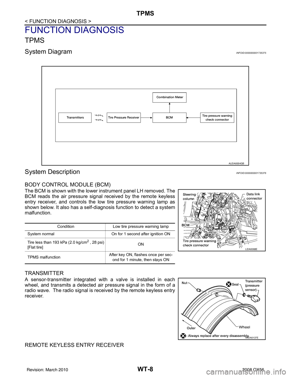
System DiagramINFOID:0000000001735375
System DescriptionINFOID:0000000001735376
BODY CONTROL MODULE (BCM)
The BCM is shown with the lower instrument panel LH removed. The
BCM reads the air pressure signal received by the remote keyless
entry receiver, and controls the low tire pressure warning lamp as
shown below. It also has a self-d iagnosis function to detect a system
malfunction.
TRANSMITTER
A sensor-transmitter integrated with a valve is installed in each
wheel, and transmits a detected air pr essure signal in the form of a
radio wave. The radio signal is received by the remote keyless entry
receiver.
REMOTE KEYLESS ENTRY RECEIVER
ALEIA0004GB
Condition Low tire pressure warning lamp
System normal On for 1 second after ignition ON
Tire less than 193 kPa (2.0 kg/cm
2 , 28 psi)
[Flat tire] ON
TPMS malfunction After key ON, flashes once per sec-
ond for 1 minute, then stays ON
LEIA0068E
WEIA0137E
Revision: March 2010 2008 QX56
Page 3955 of 4083

TPMSWT-9
< FUNCTION DIAGNOSIS >
C
DF
G H
I
J
K L
M A
B
WT
N
O P
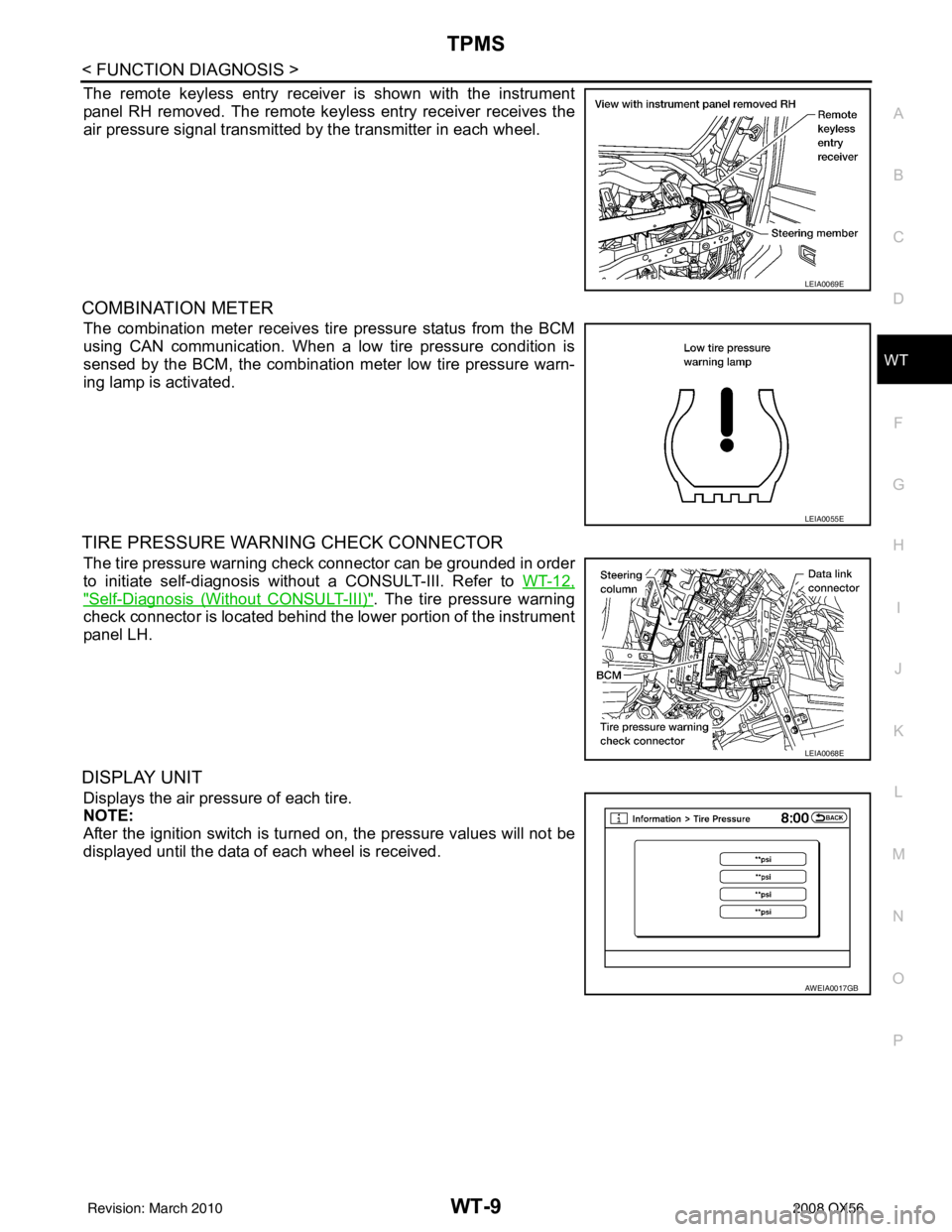
The remote keyless entry receiver is shown with the instrument
panel RH removed. The remote keyless entry receiver receives the
air pressure signal transmitted by the transmitter in each wheel.
COMBINATION METER
The combination meter receives tire pressure status from the BCM
using CAN communication. When a low tire pressure condition is
sensed by the BCM, the combination meter low tire pressure warn-
ing lamp is activated.
TIRE PRESSURE WARNING CHECK CONNECTOR
The tire pressure warning check connector can be grounded in order
to initiate self-diagnosis without a CONSULT-III. Refer to WT-12,
"Self-Diagnosis (Without CONSULT-III)". The tire pressure warning
check connector is located behind the lower portion of the instrument
panel LH.
DISPLAY UNIT
Displays the air pressure of each tire.
NOTE:
After the ignition switch is turned on, the pressure values will not be
displayed until the data of each wheel is received.
LEIA0069E
LEIA0055E
LEIA0068E
AWEIA0017GB
Revision: March 2010 2008 QX56
Page 4007 of 4083
WW-10
< FUNCTION DIAGNOSIS >
REAR WIPER AND WASHER SYSTEM
Component Parts Location
INFOID:0000000001735571
Component DescriptionINFOID:0000000001735572
1. Steering column (v iew with instrument
panel removed) 2. BCM M18, M19, M20
3. Rear washer nozzle
4. Rear wiper motor D704 5. Air cleaner case6. Front and rear washer motor connector
E105
7. Washer fluid reservoir 8. Combination switch M28 9. Glass hatch ajar switch D707
ALLIA0842ZZ
Part Description
BCM • Judges each switch status by the combination switch reading function.
• Supplies power to the rear wiper motor.
• Performs the auto stop control of the rear wiper.
Combination switch
(Wiper and washer switch) Refer to BCS-7, "
System Diagram".
Revision: March 2010
2008 QX56