2008 INFINITI QX56 power steering
[x] Cancel search: power steeringPage 1930 of 4083

EXL-2
HEADLAMP (HI) CIRCUIT ................................28
Description ........................................................... ...28
Component Function Check ...................................28
Diagnosis Procedure ..............................................28
HEADLAMP (LO) CIRCUIT ...............................30
Description ........................................................... ...30
Component Function Check ...................................30
Diagnosis Procedure ..............................................30
FRONT FOG LAMP CIRCUIT ...........................32
Description ........................................................... ...32
Component Function Check ...................................32
Diagnosis Procedure ..............................................32
PARKING LAMP CIRCUIT ................................34
Description ........................................................... ...34
Component Function Check ...................................34
Diagnosis Procedure ..............................................34
TURN SIGNAL LAMP CIRCUIT ........................37
Description ........................................................... ...37
Component Function Check ...................................37
Diagnosis Procedure ..............................................37
OPTICAL SENSOR ...........................................40
Description ..............................................................40
Component Function Check ...................................40
Diagnosis Procedure ..............................................40
HEADLAMP AIMING SWITCH ..........................42
Description ........................................................... ...42
Diagnosis Procedure ..............................................42
HEADLAMP .......................................................43
Wiring Diagram .................................................... ...43
DAYTIME LIGHT SYSTEM ................................47
Wiring Diagram .................................................... ...47
AUTO LIGHT SYSTEM ......................................54
Wiring Diagram .................................................... ...54
HEADLAMP AIMING SYSTEM (MANUAL) ......61
Wiring Diagram .................................................... ...61
FRONT FOG LAMP SYSTEM ...........................65
Wiring Diagram .................................................... ...65
TURN SIGNAL AND HAZARD WARNING
LAMP SYSTEM .............................................. ...
68
Wiring Diagram .................................................... ...68
PARKING, LICENSE PLATE AND TAIL
LAMPS SYSTEM ............................................ ...
75
Wiring Diagram .................................................... ...75
STOP LAMP ......................................................81
Wiring Diagram .................................................... ...81
BACK-UP LAMP ................................................85
Wiring Diagram .................................................... ...85
TRAILER TOW ..................................................90
Wiring Diagram .................................................... ...90
ECU DIAGNOSIS .......................................99
BCM (BODY CONTROL MODULE) ............... ...99
Description ........................................................... ...99
IPDM E/R (INTELLIGENT POWER DISTRI-
BUTION MODULE ENGINE ROOM) ................
100
Description ........................................................... .100
SYMPTOM DIAGNOSIS ...........................101
EXTERIOR LIGHTING SYSTEM SYMPTOMS ..101
Symptom Table .................................................... .101
NORMAL OPERATING CONDITION ...............103
Description ........................................................... .103
BOTH SIDE HEADLAMPS DO NOT SWITCH
TO HIGH BEAM ................................................
104
Description ........................................................... .104
Diagnosis Procedure .............................................104
BOTH SIDE HEADLAMPS (LO) ARE NOT
TURNED ON .....................................................
105
Description ............................................................105
Diagnosis Procedure .............................................105
PARKING, LICENSE PLATE AND TAIL
LAMPS ARE NOT TURNED ON ......................
106
Description ........................................................... .106
Diagnosis Procedure .............................................106
BOTH SIDE FRONT FOG LAMPS ARE NOT
TURNED ON .....................................................
107
Description ............................................................107
Diagnosis Procedure .............................................107
PRECAUTION ...........................................108
PRECAUTIONS .............................................. ..108
Precaution for Supplemental Restraint System
(SRS) "AIR BAG" and "SEAT BELT PRE-TEN-
SIONER" .............................................................. .
108
Precaution Necessary for Steering Wheel Rota-
tion After Battery Disconnect ................................
108
ON-VEHICLE REPAIR ..............................110
ADJUSTMENT AND INSPECTION ................ ..110
HEADLAMP ............................................................ .110
HEADLAMP : Aiming Adjustment .........................110
FRONT FOG LAMP ................................................ .111
FRONT FOG LAMP : Aiming Adjustment .............111
REMOVAL AND INSTALLATION .............113
HEADLAMP .................................................... ..113
Revision: March 2010 2008 QX56
Page 2036 of 4083

EXL-108
< PRECAUTION >
PRECAUTIONS
PRECAUTION
PRECAUTIONS
Precaution for Supplemental Restraint System (SRS) "AIR BAG" and "SEAT BELT
PRE-TENSIONER"
INFOID:0000000004913877
The Supplemental Restraint System such as “A IR BAG” and “SEAT BELT PRE-TENSIONER”, used along
with a front seat belt, helps to reduce the risk or severity of injury to the driver and front passenger for certain
types of collision. This system includes seat belt switch inputs and dual stage front air bag modules. The SRS
system uses the seat belt switches to determine the front air bag deployment, and may only deploy one front
air bag, depending on the severity of a collision and w hether the front occupants are belted or unbelted.
Information necessary to service the system safely is included in the SR and SB section of this Service Man-
ual.
WARNING:
• To avoid rendering the SRS inopera tive, which could increase the risk of personal injury or death in
the event of a collision which would result in air bag inflation, all maintenance must be performed by
an authorized NISSAN/INFINITI dealer.
• Improper maintenance, including in correct removal and installation of the SRS, can lead to personal
injury caused by unintent ional activation of the system. For re moval of Spiral Cable and Air Bag
Module, see the SR section.
• Do not use electrical test equipmen t on any circuit related to the SRS unless instructed to in this
Service Manual. SRS wiring harn esses can be identified by yellow and/or orange harnesses or har-
ness connectors.
PRECAUTIONS WHEN USING POWER TOOLS (AIR OR ELECTRIC) AND HAMMERS
WARNING:
• When working near the Airbag Diagnosis Sensor Unit or other Airbag System sensors with the Igni-
tion ON or engine running, DO NOT use air or electri c power tools or strike near the sensor(s) with a
hammer. Heavy vibration could activate the sensor( s) and deploy the air bag(s), possibly causing
serious injury.
• When using air or electric power tools or hammers , always switch the Ignition OFF, disconnect the
battery, and wait at least 3 minu tes before performing any service.
Precaution Necessary for Steering W heel Rotation After Battery Disconnect
INFOID:0000000006218447
NOTE:
• This Procedure is applied only to models with Intelligent Key system and NATS (NISSAN ANTI-THEFT SYS-
TEM).
• Remove and install all control units after disconnecting both battery cables with the ignition knob in the
″LOCK ″ position.
• Always use CONSULT-III to perform self-diagnosis as a part of each function inspection after finishing work.
If DTC is detected, perform trouble diagnosis according to self-diagnostic results.
For models equipped with the Intelligent Key system and NATS, an electrically controlled steering lock mech-
anism is adopted on the key cylinder.
For this reason, if the battery is disconnected or if the battery is discharged, the steering wheel will lock and
steering wheel rotation will become impossible.
If steering wheel rotation is required when battery pow er is interrupted, follow the procedure below before
starting the repair operation.
OPERATION PROCEDURE
1. Connect both battery cables. NOTE:
Supply power using jumper cables if battery is discharged.
2. Use the Intelligent Key or mechanical key to turn the ignition switch to the ″ACC ″ position. At this time, the
steering lock will be released.
3. Disconnect both battery cables. The steering lock will remain released and the steering wheel can be rotated.
4. Perform the necessary repair operation.
Revision: March 2010 2008 QX56
Page 2055 of 4083

EXT-2
< SERVICE INFORMATION >
PRECAUTIONS
SERVICE INFORMATION
PRECAUTIONS
Precaution for Supplemental Restraint System (SRS) "AIR BAG" and "SEAT BELT
PRE-TENSIONER"
INFOID:0000000004913865
The Supplemental Restraint System such as “A IR BAG” and “SEAT BELT PRE-TENSIONER”, used along
with a front seat belt, helps to reduce the risk or severity of injury to the driver and front passenger for certain
types of collision. This system includes seat belt switch inputs and dual stage front air bag modules. The SRS
system uses the seat belt switches to determine the front air bag deployment, and may only deploy one front
air bag, depending on the severity of a collision and w hether the front occupants are belted or unbelted.
Information necessary to service the system safely is included in the SR and SB section of this Service Man-
ual.
WARNING:
• To avoid rendering the SRS inopera tive, which could increase the risk of personal injury or death in
the event of a collision which would result in air bag inflation, all maintenance must be performed by
an authorized NISSAN/INFINITI dealer.
• Improper maintenance, including in correct removal and installation of the SRS, can lead to personal
injury caused by unintent ional activation of the system. For re moval of Spiral Cable and Air Bag
Module, see the SR section.
• Do not use electrical test equipmen t on any circuit related to the SRS unless instructed to in this
Service Manual. SRS wiring harn esses can be identified by yellow and/or orange harnesses or har-
ness connectors.
PRECAUTIONS WHEN USING POWER TOOLS (AIR OR ELECTRIC) AND HAMMERS
WARNING:
• When working near the Airbag Diagnosis Sensor Unit or other Airbag System sensors with the Igni-
tion ON or engine running, DO NOT use air or electri c power tools or strike near the sensor(s) with a
hammer. Heavy vibration could activate the sensor( s) and deploy the air bag(s), possibly causing
serious injury.
• When using air or electric power tools or hammers , always switch the Ignition OFF, disconnect the
battery, and wait at least 3 minu tes before performing any service.
Precaution Necessary for Steering W heel Rotation After Battery Disconnect
INFOID:0000000004913866
NOTE:
• This Procedure is applied only to models with Intelligent Key system and NATS (NISSAN ANTI-THEFT SYS-
TEM).
• Remove and install all control units after disconnecting both battery cables with the ignition knob in the
″LOCK ″ position.
• Always use CONSULT-III to perform self-diagnosis as a part of each function inspection after finishing work.
If DTC is detected, perform trouble diagnosis according to self-diagnostic results.
For models equipped with the Intelligent Key system and NATS, an electrically controlled steering lock mech-
anism is adopted on the key cylinder.
For this reason, if the battery is disconnected or if the battery is discharged, the steering wheel will lock and
steering wheel rotation will become impossible.
If steering wheel rotation is required when battery pow er is interrupted, follow the procedure below before
starting the repair operation.
OPERATION PROCEDURE
1. Connect both battery cables. NOTE:
Supply power using jumper cables if battery is discharged.
2. Use the Intelligent Key or mechanical key to turn the ignition switch to the ″ACC ″ position. At this time, the
steering lock will be released.
3. Disconnect both battery cables. The steering lock will remain released and the steering wheel can be rotated.
4. Perform the necessary repair operation.
Revision: March 2010 2008 QX56
Page 2086 of 4083

FAX-2
< PRECAUTION >
PRECAUTIONS
PRECAUTION
PRECAUTIONS
Precaution for Supplemental Restraint System (SRS) "AIR BAG" and "SEAT BELT
PRE-TENSIONER"
INFOID:0000000004886754
The Supplemental Restraint System such as “A IR BAG” and “SEAT BELT PRE-TENSIONER”, used along
with a front seat belt, helps to reduce the risk or severity of injury to the driver and front passenger for certain
types of collision. This system includes seat belt switch inputs and dual stage front air bag modules. The SRS
system uses the seat belt switches to determine the front air bag deployment, and may only deploy one front
air bag, depending on the severity of a collision and w hether the front occupants are belted or unbelted.
Information necessary to service the system safely is included in the SR and SB section of this Service Man-
ual.
WARNING:
• To avoid rendering the SRS inopera tive, which could increase the risk of personal injury or death in
the event of a collision which would result in air bag inflation, all maintenance must be performed by
an authorized NISSAN/INFINITI dealer.
• Improper maintenance, including in correct removal and installation of the SRS, can lead to personal
injury caused by unintent ional activation of the system. For re moval of Spiral Cable and Air Bag
Module, see the SR section.
• Do not use electrical test equipmen t on any circuit related to the SRS unless instructed to in this
Service Manual. SRS wiring harn esses can be identified by yellow and/or orange harnesses or har-
ness connectors.
PRECAUTIONS WHEN USING POWER TOOLS (AIR OR ELECTRIC) AND HAMMERS
WARNING:
• When working near the Airbag Diagnosis Sensor Unit or other Airbag System sensors with the Igni-
tion ON or engine running, DO NOT use air or electri c power tools or strike near the sensor(s) with a
hammer. Heavy vibration could activate the sensor( s) and deploy the air bag(s), possibly causing
serious injury.
• When using air or electric power tools or hammers , always switch the Ignition OFF, disconnect the
battery, and wait at least 3 minu tes before performing any service.
Precaution Necessary for Steering W heel Rotation After Battery Disconnect
INFOID:0000000004886755
NOTE:
• This Procedure is applied only to models with Intelligent Key system and NATS (NISSAN ANTI-THEFT SYS-
TEM).
• Remove and install all control units after disconnecting both battery cables with the ignition knob in the
″LOCK ″ position.
• Always use CONSULT-III to perform self-diagnosis as a part of each function inspection after finishing work.
If DTC is detected, perform trouble diagnosis according to self-diagnostic results.
For models equipped with the Intelligent Key system and NATS, an electrically controlled steering lock mech-
anism is adopted on the key cylinder.
For this reason, if the battery is disconnected or if the battery is discharged, the steering wheel will lock and
steering wheel rotation will become impossible.
If steering wheel rotation is required when battery pow er is interrupted, follow the procedure below before
starting the repair operation.
OPERATION PROCEDURE
1. Connect both battery cables. NOTE:
Supply power using jumper cables if battery is discharged.
2. Use the Intelligent Key or mechanical key to turn the ignition switch to the ″ACC ″ position. At this time, the
steering lock will be released.
3. Disconnect both battery cables. The steering lock will remain released and the steering wheel can be rotated.
4. Perform the necessary repair operation.
Revision: March 2010 2008 QX56
Page 2088 of 4083

FAX-4
< PREPARATION >
PREPARATION
PREPARATION
PREPARATION
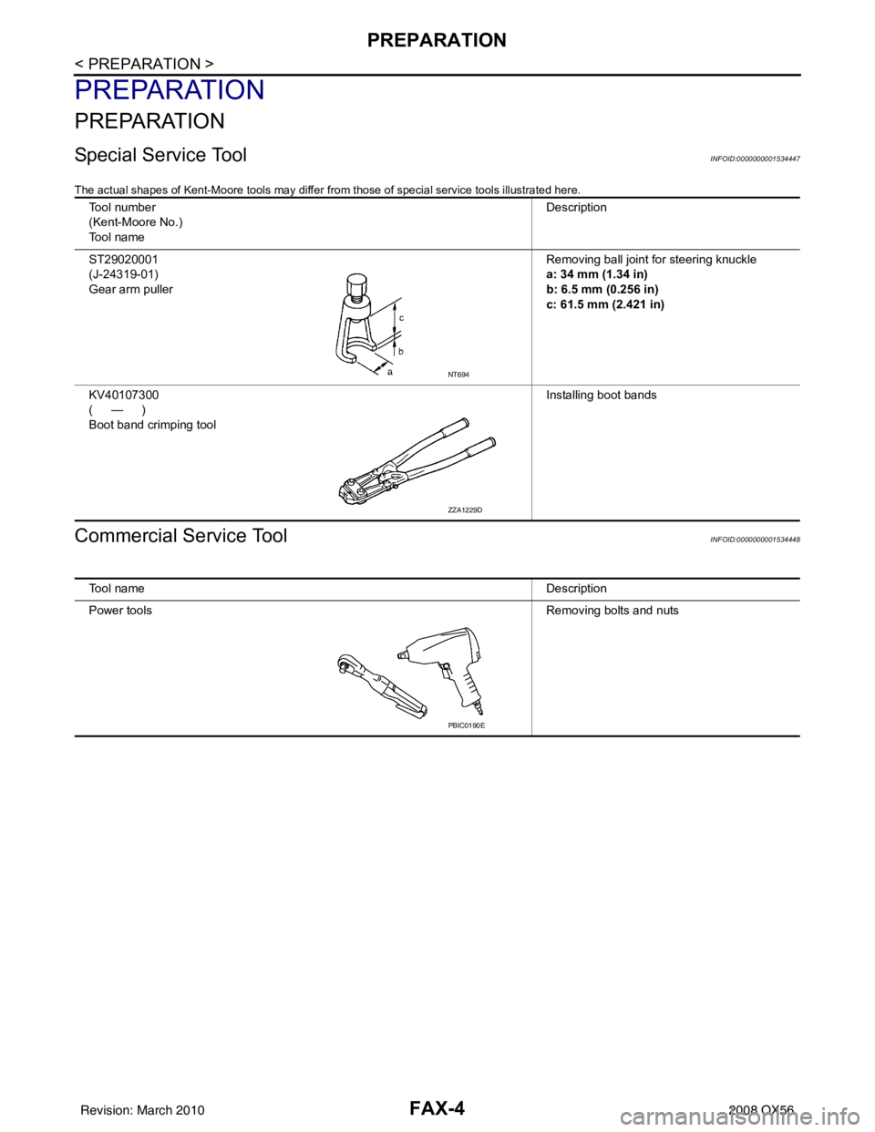
Special Service ToolINFOID:0000000001534447
The actual shapes of Kent-Moore tools may differ from those of special service tools illustrated here.
Commercial Service ToolINFOID:0000000001534448
Tool number
(Kent-Moore No.)
Tool name Description
ST29020001
(J-24319-01)
Gear arm puller Removing ball joint for steering knuckle
a: 34 mm (1.34 in)
b: 6.5 mm (0.256 in)
c: 61.5 mm (2.421 in)
KV40107300
(—)
Boot band crimping tool Installing boot bands
NT694
ZZA1229D
Tool name
Description
Power tools Removing bolts and nuts
PBIC0190E
Revision: March 2010 2008 QX56
Page 2091 of 4083

WHEEL HUBFAX-7
< REMOVAL AND INSTALLATION >
CEF
G H
I
J
K L
M A
B
FA X
N
O P
REMOVAL AND INSTALLATION
WHEEL HUB
Removal and InstallationINFOID:0000000001534453
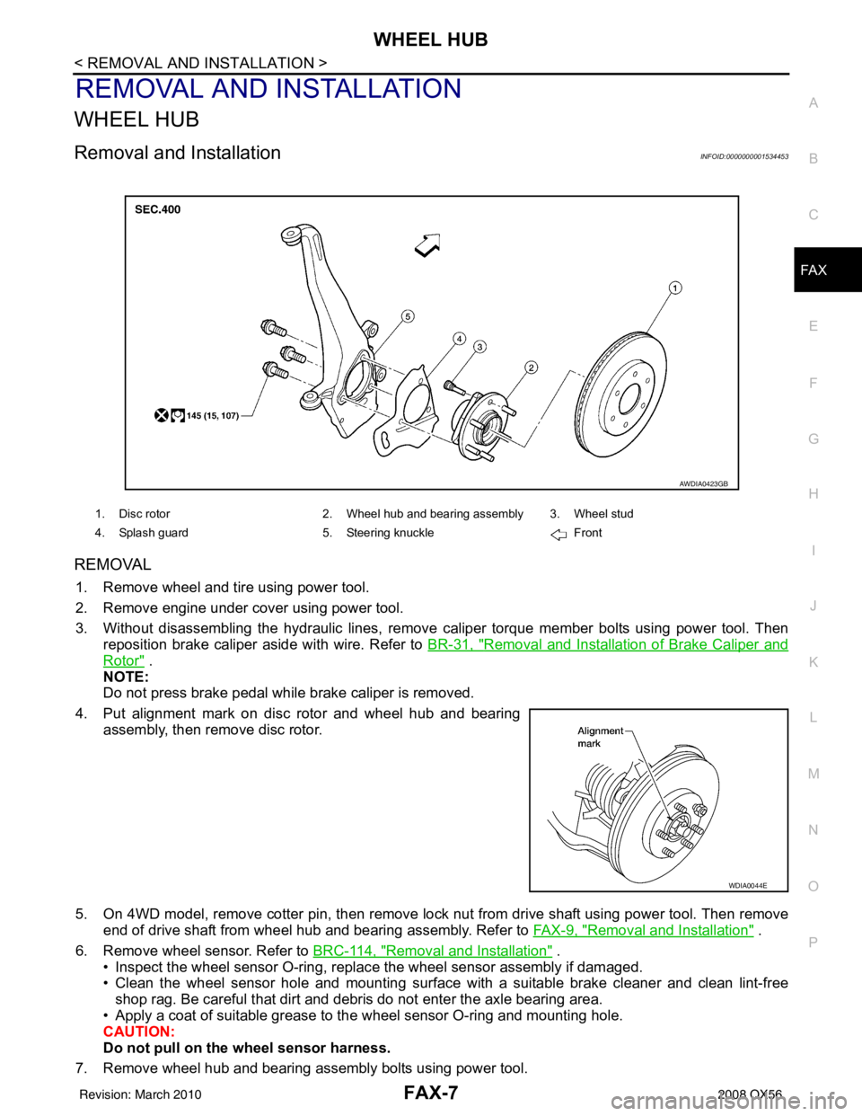
REMOVAL
1. Remove wheel and tire using power tool.
2. Remove engine under cover using power tool.
3. Without disassembling the hydraulic lines, remove caliper torque member bolts using power tool. Then
reposition brake caliper aside with wire. Refer to BR-31, "
Removal and Installation of Brake Caliper and
Rotor" .
NOTE:
Do not press brake pedal while brake caliper is removed.
4. Put alignment mark on disc rotor and wheel hub and bearing assembly, then remove disc rotor.
5. On 4WD model, remove cotter pin, then remove lock nut from drive shaft using power tool. Then remove end of drive shaft from wheel hub and bearing assembly. Refer to FAX-9, "
Removal and Installation" .
6. Remove wheel sensor. Refer to BRC-114, "
Removal and Installation" .
• Inspect the wheel sensor O-ring, replac e the wheel sensor assembly if damaged.
• Clean the wheel sensor hole and mounting surface with a suitable brake cleaner and clean lint-free shop rag. Be careful that dirt and debris do not enter the axle bearing area.
• Apply a coat of suitable grease to the wheel sensor O-ring and mounting hole.
CAUTION:
Do not pull on the wheel sensor harness.
7. Remove wheel hub and bearing assembly bolts using power tool.
1. Disc rotor 2. Wheel hub and bearing assembly 3. Wheel stud
4. Splash guard 5. Steering knuckle Front
AWDIA0423GB
WDIA0044E
Revision: March 2010 2008 QX56
Page 2093 of 4083

DRIVE SHAFTFAX-9
< REMOVAL AND INSTALLATION >
CEF
G H
I
J
K L
M A
B
FA X
N
O P
DRIVE SHAFT
Removal and InstallationINFOID:0000000001534458
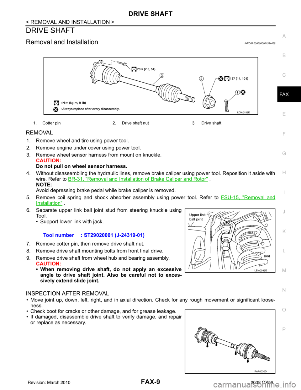
REMOVAL
1. Remove wheel and tire using power tool.
2. Remove engine under cover using power tool.
3. Remove wheel sensor harness from mount on knuckle. CAUTION:
Do not pull on wheel sensor harness.
4. Without disassembling the hydraulic lines, remove brake caliper using power tool. Reposition it aside with wire. Refer to BR-31, "
Removal and Installation of Brake Caliper and Rotor" .
NOTE:
Avoid depressing brake pedal while brake caliper is removed.
5. Remove coil spring and shock absorber assembly using power tool. Refer to FSU-15, "
Removal and
Installation" .
6. Separate upper link ball joint stud from steering knuckle using Tool.
• Support lower link with jack.
7. Remove cotter pin, then remove drive shaft nut.
8. Remove drive shaft mounting bolts from front final drive.
9. Remove drive shaft from wheel hub and bearing assembly. CAUTION:
• When removing drive shaf t, do not apply an excessive
angle to drive shaft joint. Also be careful not to exces-
sively extend slide joint.
INSPECTION AFTER REMOVAL
• Move joint up, down, left, right, and in axial directi on. Check for any rough movement or significant loose-
ness.
• Check boot for cracks or other damage, and for grease leakage.
• If damaged, disassemble drive shaft to verify damage, and repair or replace as necessary.
1. Cotter pin 2. Drive shaft nut3. Drive shaft
LDIA0159E
Tool number : ST29020001 (J-24319-01)
LEIA0095E
RAA0030D
Revision: March 2010 2008 QX56
Page 2102 of 4083

FL-2
< PRECAUTION >
PRECAUTIONS
PRECAUTION
PRECAUTIONS
Precaution for Supplemental Restraint System (SRS) "AIR BAG" and "SEAT BELT
PRE-TENSIONER"
INFOID:0000000004900804
The Supplemental Restraint System such as “A IR BAG” and “SEAT BELT PRE-TENSIONER”, used along
with a front seat belt, helps to reduce the risk or severity of injury to the driver and front passenger for certain
types of collision. This system includes seat belt switch inputs and dual stage front air bag modules. The SRS
system uses the seat belt switches to determine the front air bag deployment, and may only deploy one front
air bag, depending on the severity of a collision and w hether the front occupants are belted or unbelted.
Information necessary to service the system safely is included in the SR and SB section of this Service Man-
ual.
WARNING:
• To avoid rendering the SRS inopera tive, which could increase the risk of personal injury or death in
the event of a collision which would result in air bag inflation, all maintenance must be performed by
an authorized NISSAN/INFINITI dealer.
• Improper maintenance, including in correct removal and installation of the SRS, can lead to personal
injury caused by unintent ional activation of the system. For re moval of Spiral Cable and Air Bag
Module, see the SR section.
• Do not use electrical test equipmen t on any circuit related to the SRS unless instructed to in this
Service Manual. SRS wiring harn esses can be identified by yellow and/or orange harnesses or har-
ness connectors.
PRECAUTIONS WHEN USING POWER TOOLS (AIR OR ELECTRIC) AND HAMMERS
WARNING:
• When working near the Airbag Diagnosis Sensor Unit or other Airbag System sensors with the Igni-
tion ON or engine running, DO NOT use air or electri c power tools or strike near the sensor(s) with a
hammer. Heavy vibration could activate the sensor( s) and deploy the air bag(s), possibly causing
serious injury.
• When using air or electric power tools or hammers , always switch the Ignition OFF, disconnect the
battery, and wait at least 3 minu tes before performing any service.
Precaution Necessary for Steering W heel Rotation After Battery Disconnect
INFOID:0000000004900803
NOTE:
• This Procedure is applied only to models with Intelligent Key system and NATS (NISSAN ANTI-THEFT SYS-
TEM).
• Remove and install all control units after disconnecting both battery cables with the ignition knob in the
″LOCK ″ position.
• Always use CONSULT-III to perform self-diagnosis as a part of each function inspection after finishing work.
If DTC is detected, perform trouble diagnosis according to self-diagnostic results.
For models equipped with the Intelligent Key system and NATS, an electrically controlled steering lock mech-
anism is adopted on the key cylinder.
For this reason, if the battery is disconnected or if the battery is discharged, the steering wheel will lock and
steering wheel rotation will become impossible.
If steering wheel rotation is required when battery pow er is interrupted, follow the procedure below before
starting the repair operation.
OPERATION PROCEDURE
1. Connect both battery cables. NOTE:
Supply power using jumper cables if battery is discharged.
2. Use the Intelligent Key or mechanical key to turn the ignition switch to the ″ACC ″ position. At this time, the
steering lock will be released.
3. Disconnect both battery cables. The steering lock will remain released and the steering wheel can be rotated.
4. Perform the necessary repair operation.
Revision: March 2010 2008 QX56