2008 INFINITI QX56 power steering
[x] Cancel search: power steeringPage 1807 of 4083

EM-4
< PRECAUTION >
PRECAUTIONS
5. When the repair work is completed, return the ignition switch to the ″LOCK ″ position before connecting
the battery cables. (At this time, the steering lock mechanism will engage.)
6. Perform a self-diagnosis check of a ll control units using CONSULT-III.
Precaution for Drain Engine CoolantINFOID:0000000001538794
Drain engine coolant when engine is cooled.
Precaution for Disconnecting Fuel PipingINFOID:0000000001538795
• Before starting work, make sure no fire or spark producing items are in the work area.
• Release fuel pressure before disconnecting and disassembly.
• After disconnecting pipes, plug openings to stop fuel leakage.
Precaution for Removal and DisassemblyINFOID:0000000001538796
• When instructed to use special service tools, use the s pecified tools. Always be careful to work safely, avoid
forceful or uninstructed operations.
• Exercise maximum care to avoid damage to mating or sliding surfaces.
• Cover openings of engine system with tape or the equivalent, if necessary, to seal out foreign materials.
• Mark and arrange disassembly parts in an organi zed way for easy troubleshooting and assembly.
• When loosening nuts and bolts, as a basic rule, start with the one furthest outside, then the one diagonally opposite, and so on. If the order of loosening is specified, do exactly as specified. Power tools may be used
where noted in the step.
Precaution for Inspection, Repair and ReplacementINFOID:0000000001538797
Before repairing or replacing, thoroughly inspect parts. Inspect new replacement parts in the same way, and
replace if necessary.
Precaution for Assembly and InstallationINFOID:0000000001538798
• Use torque wrench to tighten bolts or nuts to specification.
• When tightening nuts and bolts, as a basic rule, equally tighten in several different steps starting with theones in center, then ones on inside and outside diagonally in this order. If the order of tightening is specified,
do exactly as specified.
• Replace with new gasket, packing, oil seal or O-ring.
• Thoroughly wash, clean, and air-blow each part. Carefully check engine oil or engine coolant passages for any restriction and blockage.
• Avoid damaging sliding or mating surfaces. Completely remove foreign materials such as cloth lint or dust. Before assembly, oil sliding surfaces well.
• Release air within route when refilling after draining engine coolant.
• Before starting engine, apply fuel pressure to fuel lines with turning ignition switch ON (with engine stopped). Then make sure that there are no leaks at fuel line connections.
• After repairing, start engine and increase engine s peed to check engine coolant, fuel, oil, and exhaust sys-
tems for leakage.
Parts Requiring Angular TighteningINFOID:0000000001538799
• For final tightening of the following engine parts use Tool:
- Cylinder head bolts
- Main bearing cap bolts
- Connecting rod cap bolts
- Crankshaft pulley bolt (No angle wrench is required as the bolt flange is provided with notches for angle tightening)
• Do not use a torque value for final tightening.
• The torque value for these parts are for a preliminary step.
• Ensure thread and seat surfaces are clean and lightly coated with engine oil. Tool number : KV10112100 (BT-8653-A)
Revision: March 2010
2008 QX56
Page 1816 of 4083
DRIVE BELTSEM-13
< ON-VEHICLE MAINTENANCE >
C
DE
F
G H
I
J
K L
M A
EM
NP
O
ON-VEHICLE MAINTENANCE
DRIVE BELTS
Checking Drive BeltsINFOID:0000000001538805
WARNING:
Be sure to perform when the engine is stopped.
1. Remove air duct and resonator assembly when inspecting drive belt.
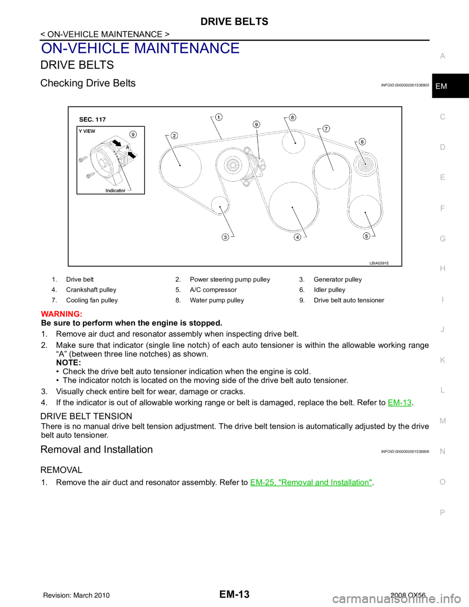
2. Make sure that indicator (single line notch) of eac
h auto tensioner is within the allowable working range
“A” (between three line notches) as shown.
NOTE:
• Check the drive belt auto tensioner indication when the engine is cold.
• The indicator notch is located on the moving side of the drive belt auto tensioner.
3. Visually check entire belt for wear, damage or cracks.
4. If the indicator is out of allowable working range or belt is damaged, replace the belt. Refer to EM-13
.
DRIVE BELT TENSION
There is no manual drive belt tension adjustment. The driv e belt tension is automatically adjusted by the drive
belt auto tensioner.
Removal and InstallationINFOID:0000000001538806
REMOVAL
1. Remove the air duct and resonator assembly. Refer to EM-25, "Removal and Installation".
1. Drive belt2. Power steering pump pulley 3. Generator pulley
4. Crankshaft pulley 5. A/C compressor6. Idler pulley
7. Cooling fan pulley 8. Water pump pulley9. Drive belt auto tensioner
LBIA0391E
Revision: March 2010 2008 QX56
Page 1848 of 4083
TIMING CHAINEM-45
< ON-VEHICLE REPAIR >
C
DE
F
G H
I
J
K L
M A
EM
NP
O
Removal and InstallationINFOID:0000000001538821
NOTE:
• To remove timing chain and associated parts, start with those on the LH bank. The procedure for removing
parts on the RH bank is omitted because it is t he same as that for removal on the LH bank.
• To install timing chain and associated parts, start with those on the RH bank. The procedure for installing parts on the LH bank is omitted because it is t he same as that for installation on the RH bank.
REMOVAL
1. Remove the engine assembly from the vehicle. Refer to EM-78, "Removal and Installation".
2. Remove the following components and related parts: • Drive belt auto tensioner and idler pulley. Refer to EM-13, "
Removal and Installation".
• Thermostat housing and water hose. Refer to CO-22, "
Removal and Installation".
• Power steering oil pump bracket. Refer to ST-26, "
Removal and Installation".
• Oil pan (lower), (upper) and oil strainer. Refer to EM-33, "
Removal and Installation".
• Ignition coil. Refer to EM-37, "
Removal and Installation".
• Rocker cover. Refer to EM-38, "
Removal and Installation".
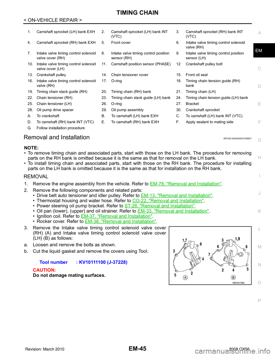
3. Remove the Intake valve timing control solenoid valve cover (RH) (A) and Intake valve timing control solenoid valve cover
(LH) (B) as follows:
a. Loosen and remove the bolts as shown.
b. Cut the liquid gasket and remove the covers using Tool.
CAUTION:
Do not damage mating surfaces.
1. Camshaft sprocket (LH) bank EXH 2. Camshaft sprocket (LH) bank INT (VTC)3. Camshaft sprocket (RH) bank INT
(VTC)
4. Camshaft sprocket (RH) bank EXH 5. Front cover 6. Intake valve timing control solenoid
valve (RH)
7. Intake valve timing control solenoid valve cover (RH) 8. Intake valve timing control position
sensor (RH) 9. Intake valve timing control position
sensor (LH)
10. Intake valve timing control solenoid valve cover (LH) 11. Camshaft position
sensor (PHASE) 12 Cran kshaft pulley bolt
13. Crankshaft pulley 14. Chain tensioner cover 15. Front oil seal
16. Intake valve timing control solenoid valve (RH) 17. O-ring
18. Timing chain tension guide (RH)
bank
19. Timing chain slack guide (RH) 20. Timing chain (RH) bank 21. Timing chain (LH)
22. Chain tensioner (RH) 23. Timing chain slack guide (LH) bank 24. Timing chain tension guide (LH) bank
25. Chain tensioner (LH) 26. O-ring 27. Bracket
28. Oil pump drive spacer 29. Oil pump assembly 30. Crankshaft sprocket
A. To crankshaft B. To camshaft (LH) bank EXH C. To camshaft (LH) bank INT (VTC)
D. To camshaft (RH) bank INT (VTC) E. To camshaft (RH) bank EXH F. Apply sealant to mating side
G. Follow installation procedure
Tool number : KV10111100 (J-37228)
WBIA0798E
Revision: March 2010 2008 QX56
Page 1855 of 4083
EM-52
< ON-VEHICLE REPAIR >
TIMING CHAIN
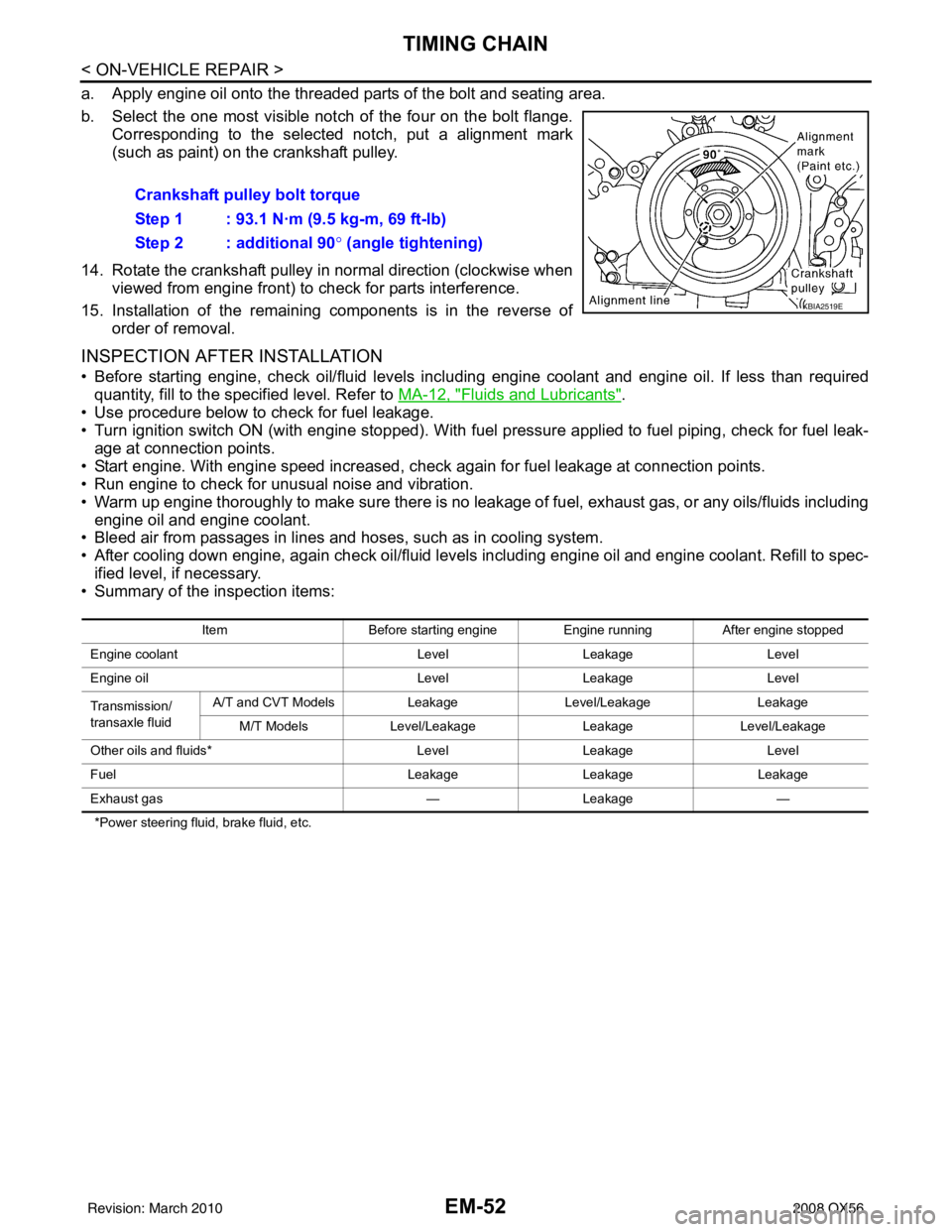
a. Apply engine oil onto the threaded parts of the bolt and seating area.
b. Select the one most visible notch of the four on the bolt flange.Corresponding to the selected notch, put a alignment mark
(such as paint) on the crankshaft pulley.
14. Rotate the crankshaft pulley in normal direction (clockwise when viewed from engine front) to check for parts interference.
15. Installation of the remaining components is in the reverse of order of removal.
INSPECTION AFTER INSTALLATION
• Before starting engine, check oil/fluid levels incl uding engine coolant and engine oil. If less than required
quantity, fill to the specified level. Refer to MA-12, "
Fluids and Lubricants".
• Use procedure below to check for fuel leakage.
• Turn ignition switch ON (with engine stopped). With fuel pressure applied to fuel piping, check for fuel leak- age at connection points.
• Start engine. With engine speed increased, che ck again for fuel leakage at connection points.
• Run engine to check for unusual noise and vibration.
• Warm up engine thoroughly to make sure there is no leakage of fuel, exhaust gas, or any oils/fluids including
engine oil and engine coolant.
• Bleed air from passages in lines and hoses, such as in cooling system.
• After cooling down engine, again check oil/fluid levels including engine oil and engine coolant. Refill to spec-
ified level, if necessary.
• Summary of the inspection items:
*Power steering fluid, brake fluid, etc.
Crankshaft pulley bolt torque
Step 1 : 93.1 N·m (9.5 kg-m, 69 ft-lb)
Step 2 : additional 90 ° (angle tightening)
KBIA2519E
Item Before starting engine Engine runningAfter engine stopped
Engine coolant LevelLeakage Level
Engine oil LevelLeakage Level
Transmission/
transaxle fluid A/T and CVT Models
LeakageLevel/Leakage Leakage
M/T Models Level/Leakage LeakageLevel/Leakage
Other oils and fluids* LevelLeakage Level
Fuel LeakageLeakage Leakage
Exhaust gas —Leakage —
Revision: March 2010 2008 QX56
Page 1873 of 4083
EM-70
< ON-VEHICLE REPAIR >
CYLINDER HEAD
*Power steering fluid, brake fluid, etc.
Disassembly and AssemblyINFOID:0000000001538829
DISASSEMBLY
1. Remove the spark plug. Refer to EM-16, "Removal and Installation".
2. Remove the valve lifter. • Identify the installation positions, and store them without mixing them up.
Item Before starting engine Engine runningAfter engine stopped
Engine coolant LevelLeakage Level
Engine oil LevelLeakage Level
Transmission/
transaxle fluid A/T and CVT Models
LeakageLevel/Leakage Leakage
M/T Models Level/Leakage LeakageLevel/Leakage
Other oils and fluids* LevelLeakage Level
Fuel LeakageLeakage Leakage
Exhaust gas —Leakage —
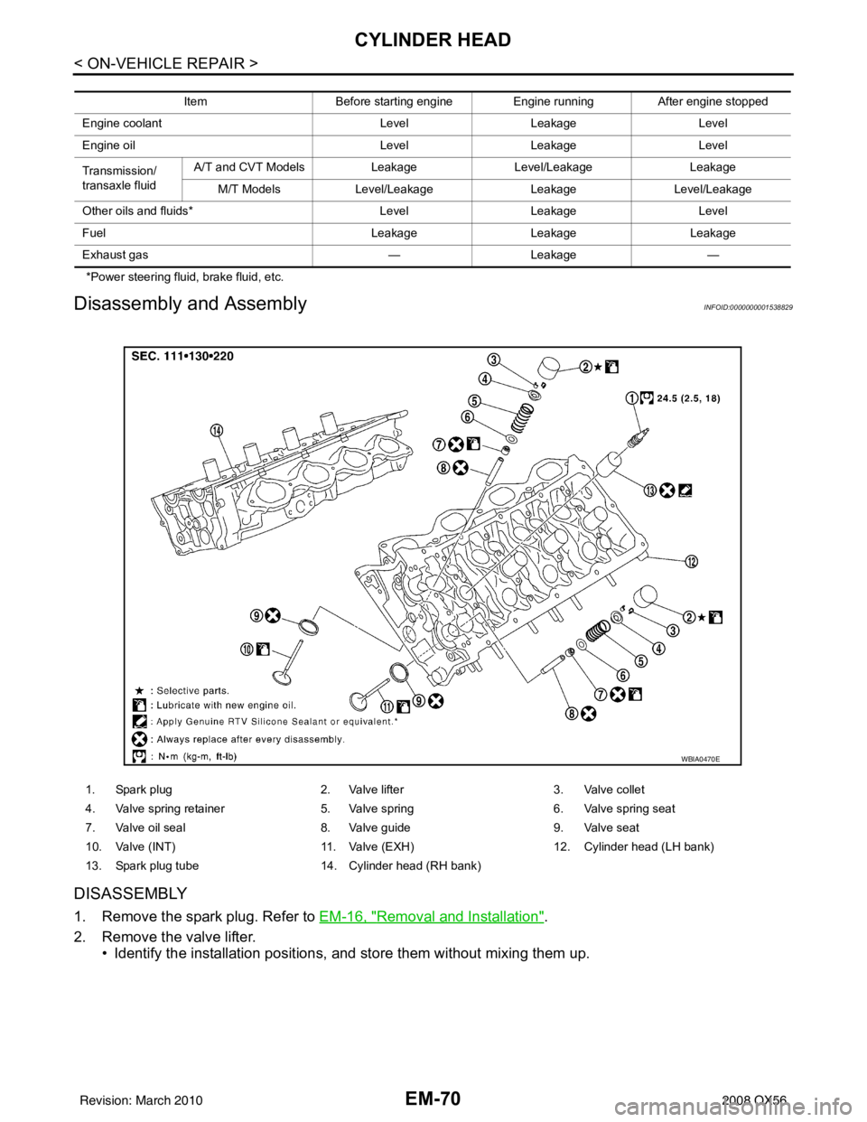
1. Spark plug 2. Valve lifter3. Valve collet
4. Valve spring retainer 5. Valve spring6. Valve spring seat
7. Valve oil seal 8. Valve guide9. Valve seat
10. Valve (INT) 11. Valve (EXH)12. Cylinder head (LH bank)
13. Spark plug tube 14. Cylinder head (RH bank)
WBIA0470E
Revision: March 2010 2008 QX56
Page 1882 of 4083
ENGINE ASSEMBLYEM-79
< REMOVAL AND INSTALLATION >
C
DE
F
G H
I
J
K L
M A
EM
NP
O
4. Remove the engine hood. Refer to
DLK-224, "Removal and Installation of Hood Assembly".
5. Remove the cowl extension. Refer to EXT-18, "
Removal and Installation".
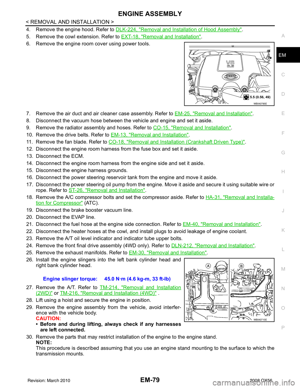
6. Remove the engine room cover using power tools.
7. Remove the air duct and air cleaner case assembly. Refer to EM-25, "
Removal and Installation".
8. Disconnect the vacuum hose between the vehicle and engine and set it aside.
9. Remove the radiator assembly and hoses. Refer to CO-15, "
Removal and Installation".
10. Remove the drive belts. Refer to EM-13, "
Removal and Installation".
11. Remove the fan blade. Refer to CO-18, "
Removal and Installation (Crankshaft Driven Type)".
12. Disconnect the engine room harness from the fuse box and set it aside.
13. Disconnect the ECM.
14. Disconnect the engine room harness from the engine side and set it aside.
15. Disconnect the engine harness grounds.
16. Disconnect the power steering reservoir t ank from the engine and move it aside.
17. Disconnect the power steering oil pump from the engine. Move it aside and secure it using suitable wire or rope. Refer to ST-26, "
Removal and Installation".
18. Remove the A/C compressor bolts and set the compressor aside. Refer to HA-31, "
Removal and Installa-
tion for Compressor" (ATC).
19. Disconnect the brake booster vacuum line.
20. Disconnect the EVAP line.
21. Disconnect the fuel hose at the engine side connection. Refer to EM-40, "
Removal and Installation".
22. Disconnect the heater hoses at the cowl, and in stall plugs to avoid leakage of engine coolant.
23. Remove the A/T oil level indicator and indicator tube upper bolts.
24. Remove the front final drive assembly (4WD only). Refer to DLN-212, "
Removal and Installation".
25. Remove the exhaust manifolds. Refer to EM-30, "
Removal and Installation".
26. Install the engine slingers into the left bank cylinder head and right bank cylinder head.
27. Remove the A/T. Refer to TM-214, "
Removal and Installation
(2WD)" or TM-216, "Removal and Installation (4WD)" .
28. Lift using a hoist and secure the engine in position.
29. Remove the engine assembly from the vehicle, avoid interfer- ence with the vehicle body.
CAUTION:
• Before and during lifting, always check if any harnessesare left connected.
30. Remove the parts that may restrict installation of the engine to the engine stand. NOTE:
This procedure is described assuming that you use an engine stand mounting to the surface to which the
transmission mounts.
WBIA0795E
Engine slinger torque: 45.0 N·m (4.6 kg-m, 33 ft-lb)
WBIA0715E
Revision: March 2010 2008 QX56
Page 1884 of 4083
ENGINE ASSEMBLYEM-81
< REMOVAL AND INSTALLATION >
C
DE
F
G H
I
J
K L
M A
EM
NP
O
• Start engine. With engine speed increased, check again for fuel leakage at connection points.
• Run engine to check for unusual noise and vibration.
• Warm up engine thoroughly to make sure there is no leak
age of fuel, exhaust gas, or any oils/fluids including
engine oil and engine coolant.
• Bleed air from passages in lines and hoses, such as in cooling system.
• After cooling down engine, again check oil/fluid levels including engine oil and engine coolant. Refill to spec- ified level, if necessary.
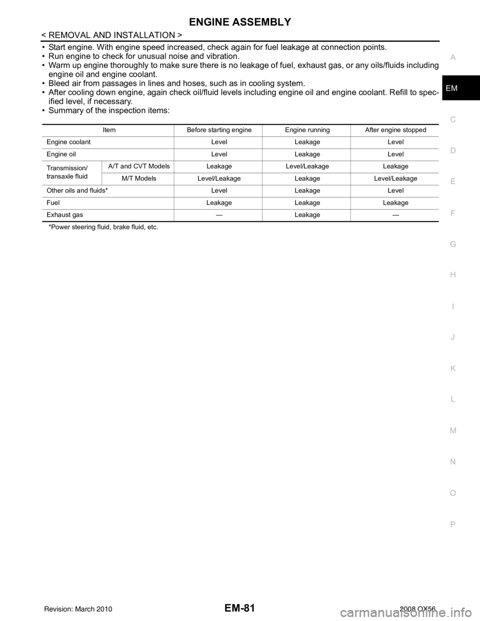
• Summary of the inspection items:
*Power steering fluid, brake fluid, etc. Item
Before starting engine Engine runningAfter engine stopped
Engine coolant LevelLeakage Level
Engine oil LevelLeakage Level
Transmission/
transaxle fluid A/T and CVT Models
LeakageLevel/Leakage Leakage
M/T Models Level/Leakage LeakageLevel/Leakage
Other oils and fluids* LevelLeakage Level
Fuel LeakageLeakageLeakage
Exhaust gas —Leakage —
Revision: March 2010 2008 QX56
Page 1923 of 4083
EX-2
< PRECAUTION >
PRECAUTIONS
PRECAUTION
PRECAUTIONS
Precaution for Supplemental Restraint System (SRS) "AIR BAG" and "SEAT BELT
PRE-TENSIONER"
INFOID:0000000004857579
The Supplemental Restraint System such as “A IR BAG” and “SEAT BELT PRE-TENSIONER”, used along
with a front seat belt, helps to reduce the risk or severity of injury to the driver and front passenger for certain
types of collision. This system includes seat belt switch inputs and dual stage front air bag modules. The SRS
system uses the seat belt switches to determine the front air bag deployment, and may only deploy one front
air bag, depending on the severity of a collision and w hether the front occupants are belted or unbelted.
Information necessary to service the system safely is included in the SR and SB section of this Service Man-
ual.
WARNING:
• To avoid rendering the SRS inopera tive, which could increase the risk of personal injury or death in
the event of a collision which would result in air bag inflation, all maintenance must be performed by
an authorized NISSAN/INFINITI dealer.
• Improper maintenance, including in correct removal and installation of the SRS, can lead to personal
injury caused by unintent ional activation of the system. For re moval of Spiral Cable and Air Bag
Module, see the SR section.
• Do not use electrical test equipmen t on any circuit related to the SRS unless instructed to in this
Service Manual. SRS wiring harn esses can be identified by yellow and/or orange harnesses or har-
ness connectors.
PRECAUTIONS WHEN USING POWER TOOLS (AIR OR ELECTRIC) AND HAMMERS
WARNING:
• When working near the Airbag Diagnosis Sensor Unit or other Airbag System sensors with the Igni-
tion ON or engine running, DO NOT use air or electri c power tools or strike near the sensor(s) with a
hammer. Heavy vibration could activate the sensor( s) and deploy the air bag(s), possibly causing
serious injury.
• When using air or electric power tools or hammers , always switch the Ignition OFF, disconnect the
battery, and wait at least 3 minu tes before performing any service.
Precaution Necessary for Steering W heel Rotation After Battery Disconnect
INFOID:0000000004857585
NOTE:
• This Procedure is applied only to models with Intelligent Key system and NATS (NISSAN ANTI-THEFT SYS-
TEM).
• Remove and install all control units after disconnecting both battery cables with the ignition knob in the
″LOCK ″ position.
• Always use CONSULT-III to perform self-diagnosis as a part of each function inspection after finishing work.
If DTC is detected, perform trouble diagnosis according to self-diagnostic results.
For models equipped with the Intelligent Key system and NATS, an electrically controlled steering lock mech-
anism is adopted on the key cylinder.
For this reason, if the battery is disconnected or if the battery is discharged, the steering wheel will lock and
steering wheel rotation will become impossible.
If steering wheel rotation is required when battery pow er is interrupted, follow the procedure below before
starting the repair operation.
OPERATION PROCEDURE
1. Connect both battery cables. NOTE:
Supply power using jumper cables if battery is discharged.
2. Use the Intelligent Key or mechanical key to turn the ignition switch to the ″ACC ″ position. At this time, the
steering lock will be released.
3. Disconnect both battery cables. The steering lock will remain released and the steering wheel can be rotated.
4. Perform the necessary repair operation.
Revision: March 2010 2008 QX56