2008 INFINITI QX56 fl sensor
[x] Cancel search: fl sensorPage 3615 of 4083
TM-68
< COMPONENT DIAGNOSIS >
P0745 PRESSURE CONTROL SOLENOID A
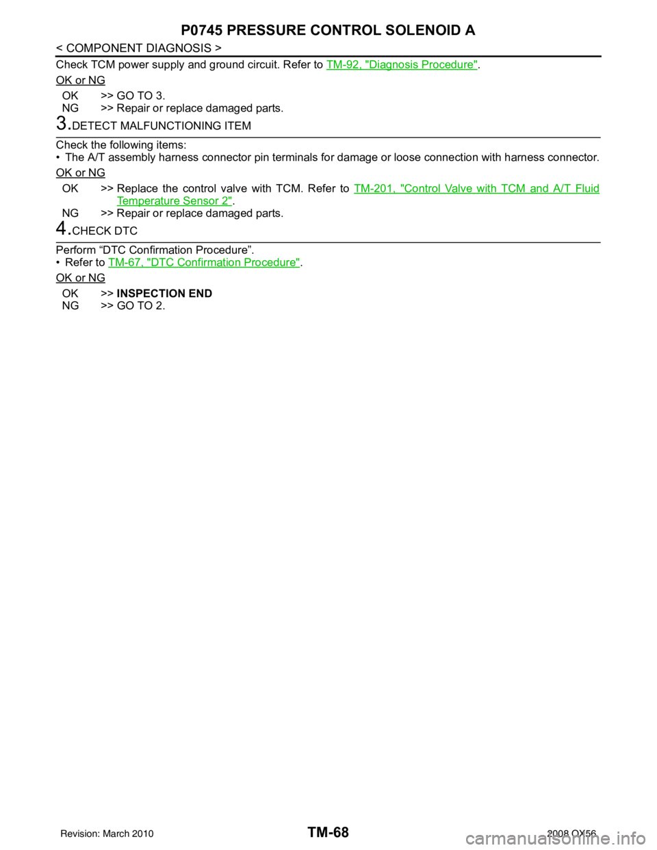
Check TCM power supply and ground circuit. Refer to TM-92, "Diagnosis Procedure".
OK or NG
OK >> GO TO 3.
NG >> Repair or replace damaged parts.
3.DETECT MALFUNCTIONING ITEM
Check the following items:
• The A/T assembly harness connector pin terminals for damage or loose connection with harness connector.
OK or NG
OK >> Replace the control valve with TCM. Refer to TM-201, "Control Valve with TCM and A/T Fluid
Temperature Sensor 2".
NG >> Repair or replace damaged parts.
4.CHECK DTC
Perform “DTC Confirmation Procedure”.
• Refer to TM-67, "
DTC Confirmation Procedure".
OK or NG
OK >> INSPECTION END
NG >> GO TO 2.
Revision: March 2010 2008 QX56
Page 3616 of 4083
P1705 TP SENSORTM-69
< COMPONENT DIAGNOSIS >
CEF
G H
I
J
K L
M A
B
TM
N
O P
P1705 TP SENSOR
DescriptionINFOID:0000000001604093
Electric throttle control actuator consists of throttle control motor, accelerator pedal position sensor, throttle
position sensor, etc. The actuator sends a signal to the ECM, and ECM sends signals to TCM with CAN com-
munication.
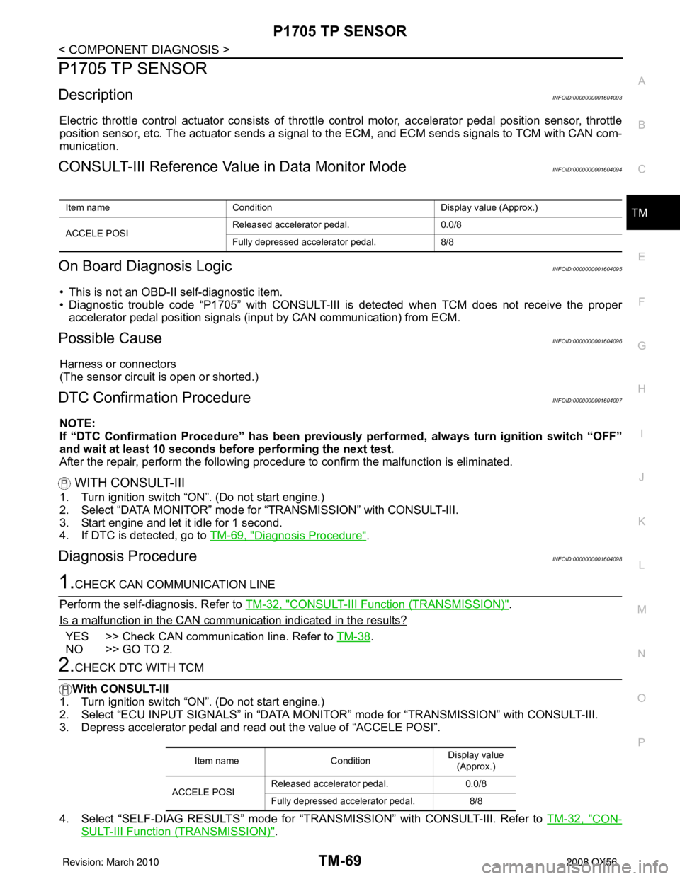
CONSULT-III Reference Val ue in Data Monitor ModeINFOID:0000000001604094
On Board Diagnosis LogicINFOID:0000000001604095
• This is not an OBD-II self-diagnostic item.
• Diagnostic trouble code “P1705” with CONSULT-III is detected when TCM does not receive the proper
accelerator pedal position signals (input by CAN communication) from ECM.
Possible CauseINFOID:0000000001604096
Harness or connectors
(The sensor circuit is open or shorted.)
DTC Confirmation ProcedureINFOID:0000000001604097
NOTE:
If “DTC Confirmation Procedure” has been previously performed, always turn ignition switch “OFF”
and wait at least 10 seconds before performing the next test.
After the repair, perform the following procedure to confirm the malfunction is eliminated.
WITH CONSULT-III
1. Turn ignition switch “ON”. (Do not start engine.)
2. Select “DATA MONITOR” mode for “TRANSMISSION” with CONSULT-III.
3. Start engine and let it idle for 1 second.
4. If DTC is detected, go to TM-69, "
Diagnosis Procedure".
Diagnosis ProcedureINFOID:0000000001604098
1.CHECK CAN COMMUNICATION LINE
Perform the self-diagnosis. Refer to TM-32, "
CONSULT-III Function (TRANSMISSION)".
Is a malfunction in the CAN communication indicated in the results?
YES >> Check CAN communication line. Refer to TM-38.
NO >> GO TO 2.
2.CHECK DTC WITH TCM
With CONSULT-III
1. Turn ignition switch “ON”. (Do not start engine.)
2. Select “ECU INPUT SIGNALS” in “DATA MONITO R” mode for “TRANSMISSION” with CONSULT-III.
3. Depress accelerator pedal and read out the value of “ACCELE POSI”.
4. Select “SELF-DIAG RESULTS” mode for “T RANSMISSION” with CONSULT-III. Refer to TM-32, "
CON-
SULT-III Function (TRANSMISSION)".
Item name Condition Display value (Approx.)
ACCELE POSI Released accelerator pedal.
0.0/8
Fully depressed accelerator pedal. 8/8
Item nameCondition Display value
(Approx.)
ACCELE POSI Released accelerator pedal.
0.0/8
Fully depressed accelerator pedal. 8/8
Revision: March 2010 2008 QX56
Page 3617 of 4083
TM-70
< COMPONENT DIAGNOSIS >
P1705 TP SENSOR
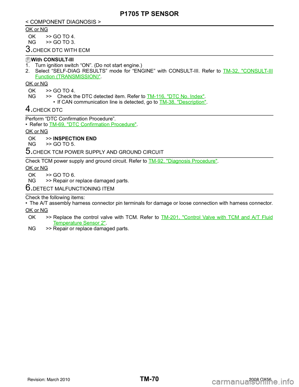
OK or NG
OK >> GO TO 4.
NG >> GO TO 3.
3.CHECK DTC WITH ECM
With CONSULT-III
1. Turn ignition switch “ON”. (Do not start engine.)
2. Select “SELF-DIAG RESULTS” mode for “ENGINE” with CONSULT-III. Refer to TM-32, "
CONSULT-III
Function (TRANSMISSION)".
OK or NG
OK >> GO TO 4.
NG >> Check the DTC detected item. Refer to TM-116, "
DTC No. Index".
• If CAN communication line is detected, go to TM-38, "
Description".
4.CHECK DTC
Perform “DTC Confirmation Procedure”.
• Refer to TM-69, "
DTC Confirmation Procedure".
OK or NG
OK >> INSPECTION END
NG >> GO TO 5.
5.CHECK TCM POWER SUPPLY AND GROUND CIRCUIT
Check TCM power supply and ground circuit. Refer to TM-92, "
Diagnosis Procedure".
OK or NG
OK >> GO TO 6.
NG >> Repair or replace damaged parts.
6.DETECT MALFUNCTIONING ITEM
Check the following items:
• The A/T assembly harness connector pin terminals for damage or loose connection with harness connector.
OK or NG
OK >> Replace the control valve with TCM. Refer to TM-201, "Control Valve with TCM and A/T Fluid
Temperature Sensor 2".
NG >> Repair or replace damaged parts.
Revision: March 2010 2008 QX56
Page 3618 of 4083
P1710 TRANSMISSION FLUID TEMPERATURE SENSOR
TM-71
< COMPONENT DIAGNOSIS >
C EF
G H
I
J
K L
M A
B
TM
N
O P
P1710 TRANSMISSION FLUI D TEMPERATURE SENSOR
DescriptionINFOID:0000000001604099
The A/T fluid temperature sensor detects the A/ T fluid temperature and sends a signal to the TCM.
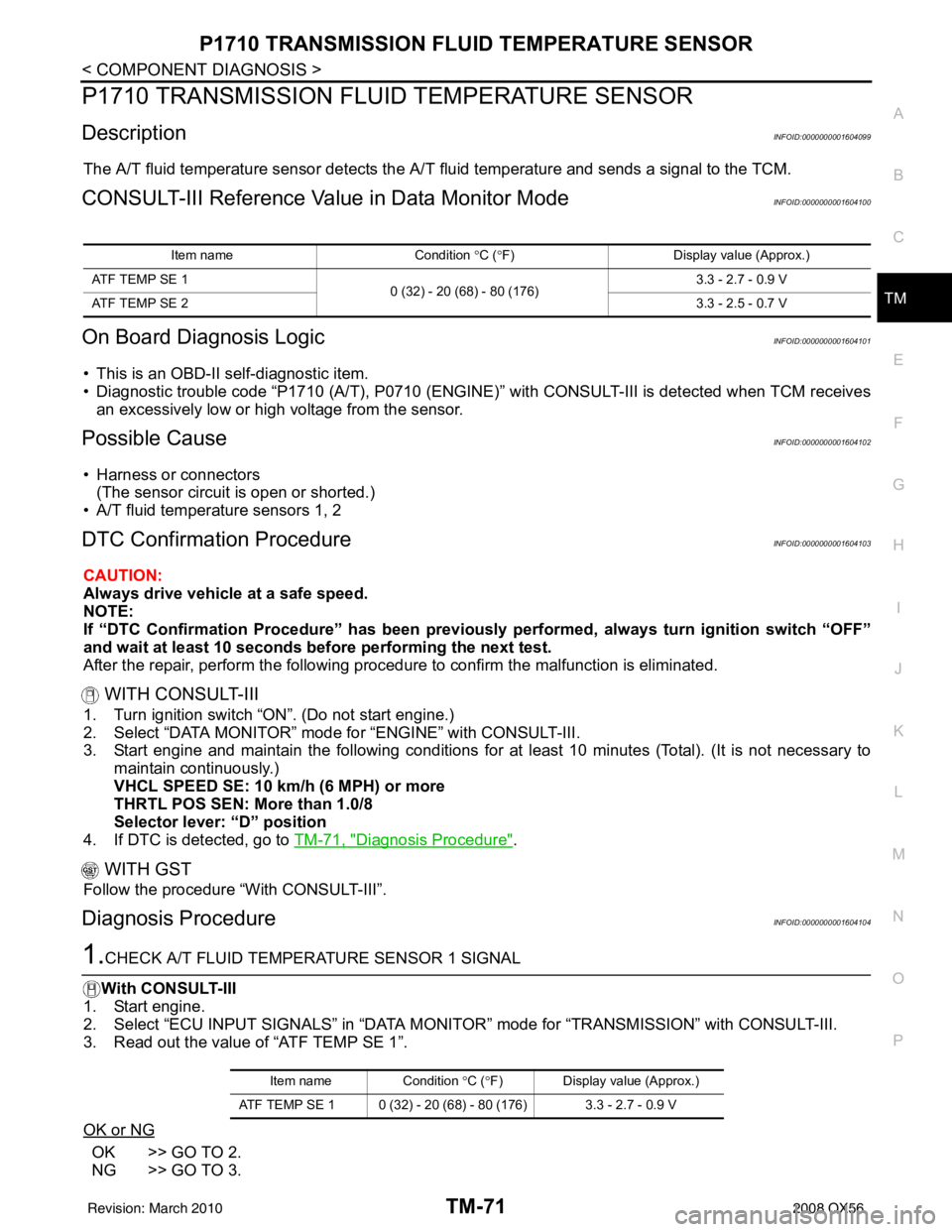
CONSULT-III Reference Value in Data Monitor ModeINFOID:0000000001604100
On Board Diagnosis LogicINFOID:0000000001604101
• This is an OBD-II self-diagnostic item.
• Diagnostic trouble code “P1710 (A/T), P0710 (ENGINE)” with CONSULT-III is detected when TCM receives
an excessively low or high voltage from the sensor.
Possible CauseINFOID:0000000001604102
• Harness or connectors (The sensor circuit is open or shorted.)
• A/T fluid temperature sensors 1, 2
DTC Confirmation ProcedureINFOID:0000000001604103
CAUTION:
Always drive vehicle at a safe speed.
NOTE:
If “DTC Confirmation Procedure” has been previously performed, always turn ignition switch “OFF”
and wait at least 10 seconds before performing the next test.
After the repair, perform the following procedure to confirm the malfunction is eliminated.
WITH CONSULT-III
1. Turn ignition switch “ON”. (Do not start engine.)
2. Select “DATA MONITOR” mode for “ENGINE” with CONSULT-III.
3. Start engine and maintain the following conditions for at least 10 minutes (Total). (It is not necessary to maintain continuously.)
VHCL SPEED SE: 10 km/h (6 MPH) or more
THRTL POS SEN: More than 1.0/8
Selector lever: “D” position
4. If DTC is detected, go to TM-71, "
Diagnosis Procedure".
WITH GST
Follow the procedure “With CONSULT-III”.
Diagnosis ProcedureINFOID:0000000001604104
1.CHECK A/T FLUID TEMPERATURE SENSOR 1 SIGNAL
With CONSULT-III
1. Start engine.
2. Select “ECU INPUT SIGNALS” in “DATA MONITO R” mode for “TRANSMISSION” with CONSULT-III.
3. Read out the value of “ATF TEMP SE 1”.
OK or NG
OK >> GO TO 2.
NG >> GO TO 3.
Item name Condition °C ( °F) Display value (Approx.)
ATF TEMP SE 1 0 (32) - 20 (68) - 80 (176) 3.3 - 2.7 - 0.9 V
ATF TEMP SE 2 3.3 - 2.5 - 0.7 V
Item nameCondition °C ( °F) Display value (Approx.)
ATF TEMP SE 1 0 (32) - 20 (68) - 80 (176) 3.3 - 2.7 - 0.9 V
Revision: March 2010 2008 QX56
Page 3619 of 4083
TM-72
< COMPONENT DIAGNOSIS >
P1710 TRANSMISSION FLUID TEMPERATURE SENSOR
2.CHECK A/T FLUID TEMPERATURE SENSOR 2 SIGNAL
With CONSULT-III
1. Start engine.
2. Select “ECU INPUT SIGNALS” in “DATA MONI TOR” mode for “TRANSMISSION” with CONSULT-III.
3. Read out the value of “ATF TEMP SE 2”.
OK or NG
OK >> GO TO 8.
NG >> GO TO 5.
3.CHECK A/T FLUID TEMPERATURE SENSOR 1
Check A/T fluid temperature sensor 1. Refer to TM-73, "
Component Inspection".
OK or NG
OK >> GO TO 4.
NG >> Replace the control valve with TCM. Refer to TM-201, "
Control Valve with TCM and A/T Fluid
Temperature Sensor 2".
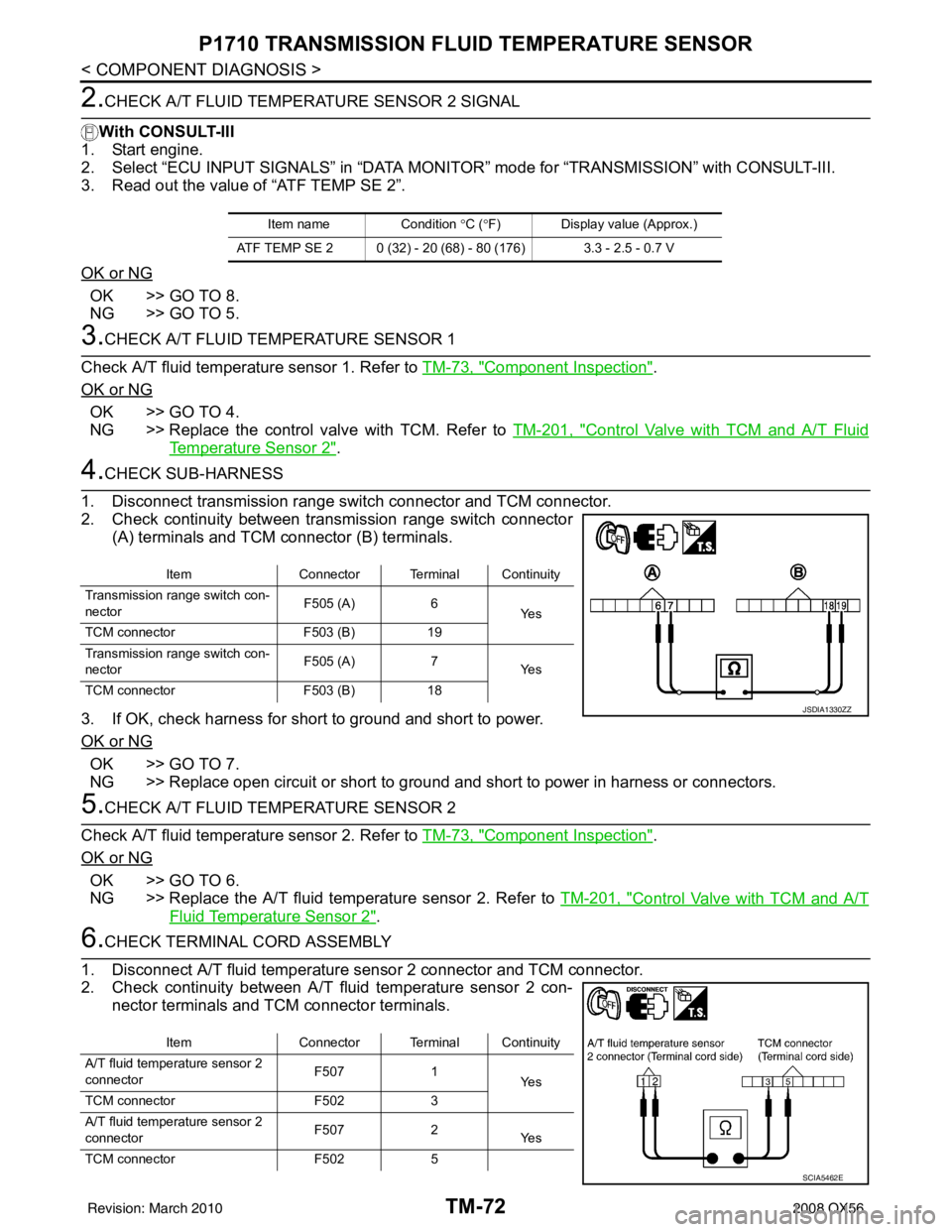
4.CHECK SUB-HARNESS
1. Disconnect transmission range switch connector and TCM connector.
2. Check continuity between transmission range switch connector (A) terminals and TCM connector (B) terminals.
3. If OK, check harness for short to ground and short to power.
OK or NG
OK >> GO TO 7.
NG >> Replace open circuit or short to ground and short to power in harness or connectors.
5.CHECK A/T FLUID TEMPERATURE SENSOR 2
Check A/T fluid temperature sensor 2. Refer to TM-73, "
Component Inspection".
OK or NG
OK >> GO TO 6.
NG >> Replace the A/T fluid temperature sensor 2. Refer to TM-201, "
Control Valve with TCM and A/T
Fluid Temperature Sensor 2".
6.CHECK TERMINAL CORD ASSEMBLY
1. Disconnect A/T fluid temperature sensor 2 connector and TCM connector.
2. Check continuity between A/T fluid temperature sensor 2 con- nector terminals and TCM connector terminals.
Item name Condition °C (°F) Display value (Approx.)
ATF TEMP SE 2 0 (32) - 20 (68) - 80 (176) 3.3 - 2.5 - 0.7 V
Item Connector Terminal Continuity
Transmission range switch con-
nector F505 (A)
6
Ye s
TCM connector F503 (B)19
Transmission range switch con-
nector F505 (A)
7
Ye s
TCM connector F503 (B)18
JSDIA1330ZZ
Item Connector Terminal Continuity
A/T fluid temperature sensor 2
connector F507
1
Ye s
TCM connector F5023
A/T fluid temperature sensor 2
connector F507
2
Ye s
TCM connector F5025
SCIA5462E
Revision: March 2010 2008 QX56
Page 3620 of 4083
P1710 TRANSMISSION FLUID TEMPERATURE SENSOR
TM-73
< COMPONENT DIAGNOSIS >
C EF
G H
I
J
K L
M A
B
TM
N
O P
3. If OK, check harness for short to ground and short to power.
OK or NG
OK >> GO TO 7.
NG >> Replace open circuit or short to ground and short to power in harness or connectors.
7.CHECK TCM POWER SUPPLY AND GROUND CIRCUIT
1. Check TCM power supply and ground circuit. Refer to TM-92, "
Diagnosis Procedure".
2. Reinstall any part removed.
OK or NG
OK >> Replace the control valve with TCM. Refer to TM-201, "Control Valve with TCM and A/T Fluid
Temperature Sensor 2".
NG >> Repair or replace damaged parts.
8.CHECK DTC
Perform “DTC Confirmation Procedure”.
• Refer to TM-71, "
DTC Confirmation Procedure".
OK or NG
OK >> INSPECTION END
NG >> GO TO 1.
Component InspectionINFOID:0000000001604105
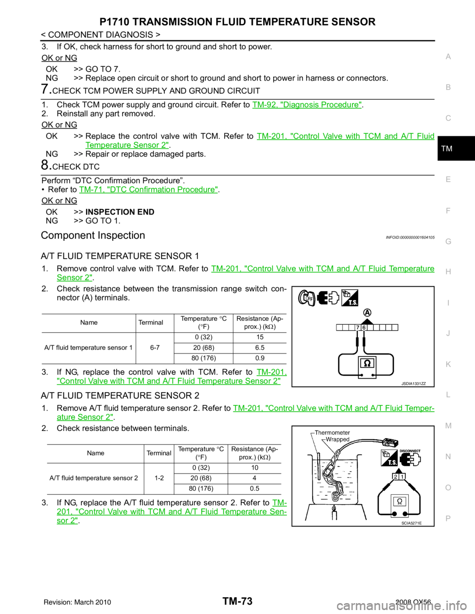
A/T FLUID TEMPERATURE SENSOR 1
1. Remove control valve with TCM. Refer to TM-201, "Control Valve with TCM and A/T Fluid Temperature
Sensor 2".
2. Check resistance between the transmission range switch con- nector (A) terminals.
3. If NG, replace the control valve with TCM. Refer to TM-201,
"Control Valve with TCM and A/T Fluid Temperature Sensor 2"
A/T FLUID TEMPERATURE SENSOR 2
1. Remove A/T fluid temperature sensor 2. Refer to TM-201, "Control Valve with TCM and A/T Fluid Temper-
ature Sensor 2".
2. Check resistance between terminals.
3. If NG, replace the A/T fluid te mperature sensor 2. Refer to TM-
201, "Control Valve with TCM and A/T Fluid Temperature Sen-
sor 2".
NameTerminalTemperature
°C
(° F) Resistance (Ap-
prox.) (k Ω)
0 (32) 15
A/T fluid temperature sensor 1 6-7 20 (68)6.5
80 (176) 0.9
JSDIA1331ZZ
NameTerminalTemperature
°C
(° F) Resistance (Ap-
prox.) (k Ω)
0 (32) 10
A/T fluid temperature sensor 2 1-2 20 (68) 4
80 (176) 0.5
SCIA5271E
Revision: March 2010 2008 QX56
Page 3621 of 4083
TM-74
< COMPONENT DIAGNOSIS >
P1721 VEHICLE SPEED SIGNAL
P1721 VEHICLE SPEED SIGNAL
DescriptionINFOID:0000000001604106
The vehicle speed signal is transmitted from combination meter to TCM by CAN communication line. The sig-
nal functions as an auxiliary device to the output speed sensor when it is malfunctioning. The TCM will then
use the vehicle speed signal.
CONSULT-III Reference Value in Data Monitor ModeINFOID:0000000001604107
On Board Diagn osis LogicINFOID:0000000001604108
• This is not an OBD-II self-diagnostic item.
• Diagnostic trouble code “P1721” with CONSULT-III is det ected when TCM does not receive the proper vehi-
cle speed signal (input by CAN communication) from combination meter.
Possible CauseINFOID:0000000001604109
Harness or connectors
(The sensor circuit is open or shorted.)
DTC Confirmation ProcedureINFOID:0000000001604110
CAUTION:
Always drive vehicle at a safe speed.
NOTE:
If “DTC Confirmation Procedure” has been previously performed, always turn ignition switch “OFF”
and wait at least 10 seconds before performing the next test.
After the repair, perform the following proc edure to confirm the malfunction is eliminated.
WITH CONSULT-III
1. Turn ignition switch “ON”. (Do not start engine.)
2. Select “DATA MONITOR” mode for “TRANSMISSION” with CONSULT-III.
3. Start engine and maintain the following conditions for at least 5 consecutive seconds. ACCELE POS: 1/8 or less
VHCL SPEED SE: 30 km/h (17 MPH) or more
4. If DTC is detected, go to TM-74, "
Diagnosis Procedure".
Diagnosis ProcedureINFOID:0000000001604111
1.CHECK CAN COMMUNICATION LINE
Perform the self-diagnosis. Refer TM-32, "
CONSULT-III Function (TRANSMISSION)".
Is a malfunction in the CAN communication indicated in the results?
YES >> Check CAN communication line. Refer to TM-38.
NO >> GO TO 2.
2.CHECK INPUT SIGNAL
With CONSULT-III
1. Start engine.
2. Select “ECU INPUT SIGNALS” in “DATA MONI TOR” mode for “TRANSMISSION” with CONSULT-III.
3. Drive vehicle and read out the value of “VHCL/S SE·MTR”.
OK or NG
Item name Condition Display value (km/h)
VHCL/S SE·MTR During driving Approximately matches the speedometer reading.
Item nameCondition Displa y value (Approx.)(km/h)
VHCL/S SE·MTR During driving Approximately matches the speed-
ometer reading.
Revision: March 2010
2008 QX56
Page 3622 of 4083
P1721 VEHICLE SPEED SIGNALTM-75
< COMPONENT DIAGNOSIS >
CEF
G H
I
J
K L
M A
B
TM
N
O P
OK >> GO TO 4.
NG >> GO TO 3.
3.CHECK COMBINATION METERS
Check combination meter. Refer to MWI-4, "
Work Flow".
OK or NG
OK >> GO TO 4.
NG >> Repair or replace damaged parts.
4.CHECK DTC
Perform “DTC Confirmation Procedure”.
• Refer to TM-74, "
DTC Confirmation Procedure".
OK or NG
OK >> INSPECTION END
NG >> GO TO 5.
5.CHECK TCM POWER SUPPLY AND GROUND CIRCUIT
Check TCM power supply and ground circuit. Refer to TM-92, "
Diagnosis Procedure".
OK or NG
OK >> GO TO 6.
NG >> Repair or replace damaged parts.
6.DETECT MALFUNCTIONING ITEM
Check the following items:
• The A/T assembly harness connector pin terminals for damage or loose connection with harness connector.
OK or NG
OK >> Replace the control valve with TCM. Refer to TM-201, "Control Valve with TCM and A/T Fluid
Temperature Sensor 2".
NG >> Repair or replace damaged parts.
Revision: March 2010 2008 QX56