2008 INFINITI QX56 maintenance
[x] Cancel search: maintenancePage 2166 of 4083

GI-24
< PRECAUTION >
PRECAUTIONS
PRECAUTION
PRECAUTIONS
DescriptionINFOID:0000000001539205
Observe the following precautions to ensure safe and proper servicing. These precautions are not
described in each individual section.
Precaution for Supplemental Restraint Syst em (SRS) "AIR BAG" and "SEAT BELT
PRE-TENSIONER"
INFOID:0000000006054104
The Supplemental Restraint System such as “A IR BAG” and “SEAT BELT PRE-TENSIONER”, used along
with a front seat belt, helps to reduce the risk or severity of injury to the driver and front passenger for certain
types of collision. This system includes seat belt switch inputs and dual stage front air bag modules. The SRS
system uses the seat belt switches to determine the front air bag deployment, and may only deploy one front
air bag, depending on the severity of a collision and w hether the front occupants are belted or unbelted.
Information necessary to service the system safely is included in the SR and SB section of this Service Man-
ual.
WARNING:
• To avoid rendering the SRS inopera tive, which could increase the risk of personal injury or death in
the event of a collision which would result in air bag inflation, all maintenance must be performed by
an authorized NISSAN/INFINITI dealer.
• Improper maintenance, including in correct removal and installation of the SRS, can lead to personal
injury caused by unintent ional activation of the system. For re moval of Spiral Cable and Air Bag
Module, see the SR section.
• Do not use electrical test equipmen t on any circuit related to the SRS unless instructed to in this
Service Manual. SRS wiring harn esses can be identified by yellow and/or orange harnesses or har-
ness connectors.
PRECAUTIONS WHEN USING POWER TOOLS (AIR OR ELECTRIC) AND HAMMERS
WARNING:
• When working near the Airbag Diagnosis Sensor Unit or other Airbag System sensors with the Igni-
tion ON or engine running, DO NOT use air or electri c power tools or strike near the sensor(s) with a
hammer. Heavy vibration could activate the sensor( s) and deploy the air bag(s), possibly causing
serious injury.
• When using air or electric power tools or hammers , always switch the Ignition OFF, disconnect the
battery, and wait at least 3 minu tes before performing any service.
Precaution Necessary for Steering W heel Rotation After Battery Disconnect
INFOID:0000000004900859
NOTE:
• This Procedure is applied only to models with Intelligent Key system and NATS (NISSAN ANTI-THEFT SYS-
TEM).
• Remove and install all control units after disconnecting both battery cables with the ignition knob in the
″LOCK ″ position.
• Always use CONSULT-III to perform self-diagnosis as a part of each function inspection after finishing work.
If DTC is detected, perform trouble diagnosis according to self-diagnostic results.
For models equipped with the Intelligent Key system and NATS, an electrically controlled steering lock mech-
anism is adopted on the key cylinder.
For this reason, if the battery is disconnected or if the battery is discharged, the steering wheel will lock and
steering wheel rotation will become impossible.
If steering wheel rotation is required when battery pow er is interrupted, follow the procedure below before
starting the repair operation.
OPERATION PROCEDURE
1. Connect both battery cables. NOTE:
Supply power using jumper cables if battery is discharged.
Revision: March 2010 2008 QX56
Page 2192 of 4083

GW-2
< PRECAUTION >
PRECAUTIONS
PRECAUTION
PRECAUTIONS
Precaution for Supplemental Restraint System (SRS) "AIR BAG" and "SEAT BELT
PRE-TENSIONER"
INFOID:0000000004884108
The Supplemental Restraint System such as “A IR BAG” and “SEAT BELT PRE-TENSIONER”, used along
with a front seat belt, helps to reduce the risk or severity of injury to the driver and front passenger for certain
types of collision. This system includes seat belt switch inputs and dual stage front air bag modules. The SRS
system uses the seat belt switches to determine the front air bag deployment, and may only deploy one front
air bag, depending on the severity of a collision and w hether the front occupants are belted or unbelted.
Information necessary to service the system safely is included in the SR and SB section of this Service Man-
ual.
WARNING:
• To avoid rendering the SRS inopera tive, which could increase the risk of personal injury or death in
the event of a collision which would result in air bag inflation, all maintenance must be performed by
an authorized NISSAN/INFINITI dealer.
• Improper maintenance, including in correct removal and installation of the SRS, can lead to personal
injury caused by unintent ional activation of the system. For re moval of Spiral Cable and Air Bag
Module, see the SR section.
• Do not use electrical test equipmen t on any circuit related to the SRS unless instructed to in this
Service Manual. SRS wiring harn esses can be identified by yellow and/or orange harnesses or har-
ness connectors.
PRECAUTIONS WHEN USING POWER TOOLS (AIR OR ELECTRIC) AND HAMMERS
WARNING:
• When working near the Airbag Diagnosis Sensor Unit or other Airbag System sensors with the Igni-
tion ON or engine running, DO NOT use air or electri c power tools or strike near the sensor(s) with a
hammer. Heavy vibration could activate the sensor( s) and deploy the air bag(s), possibly causing
serious injury.
• When using air or electric power tools or hammers , always switch the Ignition OFF, disconnect the
battery, and wait at least 3 minu tes before performing any service.
Precaution Necessary for Steering W heel Rotation After Battery Disconnect
INFOID:0000000004881261
NOTE:
• This Procedure is applied only to models with Intelligent Key system and NATS (NISSAN ANTI-THEFT SYS-
TEM).
• Remove and install all control units after disconnecting both battery cables with the ignition knob in the
″LOCK ″ position.
• Always use CONSULT-III to perform self-diagnosis as a part of each function inspection after finishing work.
If DTC is detected, perform trouble diagnosis according to self-diagnostic results.
For models equipped with the Intelligent Key system and NATS, an electrically controlled steering lock mech-
anism is adopted on the key cylinder.
For this reason, if the battery is disconnected or if the battery is discharged, the steering wheel will lock and
steering wheel rotation will become impossible.
If steering wheel rotation is required when battery pow er is interrupted, follow the procedure below before
starting the repair operation.
OPERATION PROCEDURE
1. Connect both battery cables. NOTE:
Supply power using jumper cables if battery is discharged.
2. Use the Intelligent Key or mechanical key to turn the ignition switch to the ″ACC ″ position. At this time, the
steering lock will be released.
3. Disconnect both battery cables. The steering lock will remain released and the steering wheel can be rotated.
4. Perform the necessary repair operation.
Revision: March 2010 2008 QX56
Page 2206 of 4083

HA-1
VENTILATION, HEATER & AIR CONDITIONER
C
DE
F
G H
J
K L
M
SECTION HA
A
B
HA
N
O P
CONTENTS
HEATER & AIR CONDITIONING SYSTEM
PRECAUTION ....... ........................................3
PRECAUTIONS .............................................. .....3
Precaution for Supplemental Restraint System
(SRS) "AIR BAG" and "SEAT BELT PRE-TEN-
SIONER" ............................................................. ......
3
Precaution Necessary for Steering Wheel Rota-
tion After Battery Disconnect ............................... ......
3
Precaution for Working with HFC-134a (R-134a) ......4
Precaution for Procedure without Cowl Top Cover ......4
Contaminated Refrigerant .........................................4
General Refrigerant Precaution ................................5
Precaution for Leak Detection Dye ...........................5
A/C Identification Label .............................................5
Precaution for Refrigerant Connection ......................5
Precaution for Service of Compressor ................ ....10
Precaution for Service Equipment ....................... ....10
PREPARATION ...........................................13
PREPARATION .............................................. ....13
Special Service Tool ........................................... ....13
HFC-134a (R-134a) Service Tool and Equipment ....13
Commercial Service Tool ........................................16
FUNCTION DIAGNOSIS ..............................17
REFRIGERATION SYSTEM .......................... ....17
Refrigerant Cycle ................................................ ....17
Refrigerant System Protection ................................17
OIL .................................................................. ....19
Maintenance of Oil in Compressor ...................... ....19
ON-VEHICLE MAINTENANCE ....................20
REFRIGERATION SYSTEM .......................... ....20
HFC-134a (R-134a) Service Procedure ..................20
OIL .................................................................. ....22
Maintenance of Oil Quantity in Compressor ....... ....22
FLUORESCENT LEAK DETECTOR ................24
Checking of Refrigerant Leaks ................................24
Checking System for Leaks Using the Fluorescent
Dye Leak Detector ............................................... ....
24
Dye Injection ............................................................24
ELECTRICAL LEAK DETECTOR ....................26
Checking of Refrigerant Leaks ................................26
Electronic Refrigerant Leak Detector ................... ....26
ON-VEHICLE REPAIR .................................29
REFRIGERATION SYSTEM .............................29
Component .......................................................... ....29
COMPRESSOR .................................................31
Removal and Installation for Compressor ...............31
Removal and Installation for Compressor Clutch ....32
LOW-PRESSURE FLEXIBLE HOSE ................36
Removal and Installation for Low-Pressure Flexi-
ble Hose .............................................................. ....
36
LOW-PRESSURE PIPE ....................................37
Removal and Installation for Low-Pressure Pipe .....37
Removal and Installation for Rear High- and Low-
Pressure A/C and Heater Core Pipes ......................
37
Removal and Installation for Underfloor Rear
High- and Low-Pressure A/C and Heater Core
Pipes ........................................................................
38
HIGH-PRESSURE FLEXIBLE HOSE ...............40
Removal and Installation for High-Pressure Flexi-
ble Hose ..................................................................
40
HIGH-PRESSURE PIPE ....................................41
Removal and Installation for High-Pressure Pipe ....41
Removal and Installation for Rear High- and Low-
Pressure A/C and Heater Core Pipes .................. ....
41
Removal and Installation for Underfloor Rear
High- and Low-Pressure A/C and Heater Core
Pipes ........................................................................
43
Revision: March 2010 2008 QX56
Page 2208 of 4083

PRECAUTIONSHA-3
< PRECAUTION >
C
DE
F
G H
J
K L
M A
B
HA
N
O P
PRECAUTION
PRECAUTIONS
Precaution for Supplemental Restraint System (SRS) "AIR BAG" and "SEAT BELT
PRE-TENSIONER"
INFOID:0000000004884163
The Supplemental Restraint System such as “AIR BAG” and “SEAT BELT PRE-TENSIONER”, used along
with a front seat belt, helps to reduce the risk or severi ty of injury to the driver and front passenger for certain
types of collision. This system includes seat belt switch inputs and dual stage front air bag modules. The SRS
system uses the seat belt switches to determine the front air bag deployment, and may only deploy one front
air bag, depending on the severity of a collision and w hether the front occupants are belted or unbelted.
Information necessary to service the system safely is included in the SR and SB section of this Service Man-
ual.
WARNING:
• To avoid rendering the SRS inoper ative, which could increase the risk of personal injury or death in
the event of a collision which would result in air bag inflation, all maintenance must be performed by
an authorized NISSAN/INFINITI dealer.
• Improper maintenance, including in correct removal and installation of the SRS, can lead to personal
injury caused by unintentional act ivation of the system. For removal of Spiral Cable and Air Bag
Module, see the SR section.
• Do not use electrical test equipm ent on any circuit related to the SRS unless instructed to in this
Service Manual. SRS wiring harnesses can be identi fied by yellow and/or orange harnesses or har-
ness connectors.
PRECAUTIONS WHEN USING POWER TOOLS (AIR OR ELECTRIC) AND HAMMERS
WARNING:
• When working near the Airbag Diagnosis Sensor Un it or other Airbag System sensors with the Igni-
tion ON or engine running, DO NOT use air or el ectric power tools or strike near the sensor(s) with a
hammer. Heavy vibration could activate the sensor( s) and deploy the air bag(s), possibly causing
serious injury.
• When using air or electric power tools or hammers, always switch the Ignition OFF, disconnect the battery, and wait at least 3 minutes before performing any service.
Precaution Necessary for Steering Wheel Rotation After Battery Disconnect
INFOID:0000000004884164
NOTE:
• This Procedure is applied only to models with Intelligent Key system and NATS (NISSAN ANTI-THEFT SYS-
TEM).
• Remove and install all control units after disconnecti ng both battery cables with the ignition knob in the
″ LOCK ″ position.
• Always use CONSULT-III to perform self-diagnosis as a part of each function inspection after finishing work.
If DTC is detected, perform trouble diagnosis according to self-diagnostic results.
For models equipped with the Intelligent Key system and NATS , an electrically controlled steering lock mech-
anism is adopted on the key cylinder.
For this reason, if the battery is disconnected or if the battery is discharged, the steering wheel will lock and
steering wheel rotation will become impossible.
If steering wheel rotation is required when battery power is interrupted, follow the procedure below before
starting the repair operation.
OPERATION PROCEDURE
1. Connect both battery cables. NOTE:
Supply power using jumper cables if battery is discharged.
2. Use the Intelligent Key or mechanical key to turn the ignition switch to the ″ACC ″ position. At this time, the
steering lock will be released.
3. Disconnect both battery cables. The steering lock will remain released and the steering wheel can be
rotated.
4. Perform the necessary repair operation.
Revision: March 2010 2008 QX56
Page 2215 of 4083

HA-10
< PRECAUTION >
PRECAUTIONS
Precaution for Service of Compressor
INFOID:0000000001516636
• Plug all openings to prevent moisture and foreign matter from entering.
• When the compressor is removed, store it in th e same position as it is when mounted on the car.
• When replacing or repairing compressor, follow “Maintenance of Oil Quantity in Compressor”
exactly. Refer to HA-22, "
Maintenance of Oil Quantity in Compressor".
• Keep friction surfaces between clut ch and pulley clean. If the surface is contaminated with oil, wipe
it off by using a clean waste cloth moistened with thinner.
• After compressor service operation, turn the compressor shaft by ha nd more than 5 turns in both
directions. This will equally distribute oil inside the compressor. After the compressor is installed,
let the engine idle and oper ate the compressor for 1 hour.
• After replacing the compressor magnet clutch, apply voltage to the new one and check for normal
operation. Refer to HA-32, "
Removal and Installation for Compressor Clutch".
Precaution for Service EquipmentINFOID:0000000001516637
RECOVERY/RECYCLING EQUIPMENT
Follow the manufacturer's instructions for machi ne operation and machine maintenance. Never introduce any
refrigerant other than that specified into the machine.
ELECTRONIC LEAK DETECTOR
Follow the manufacturer's instructions for tester operation and tester maintenance.
VACUUM PUMP
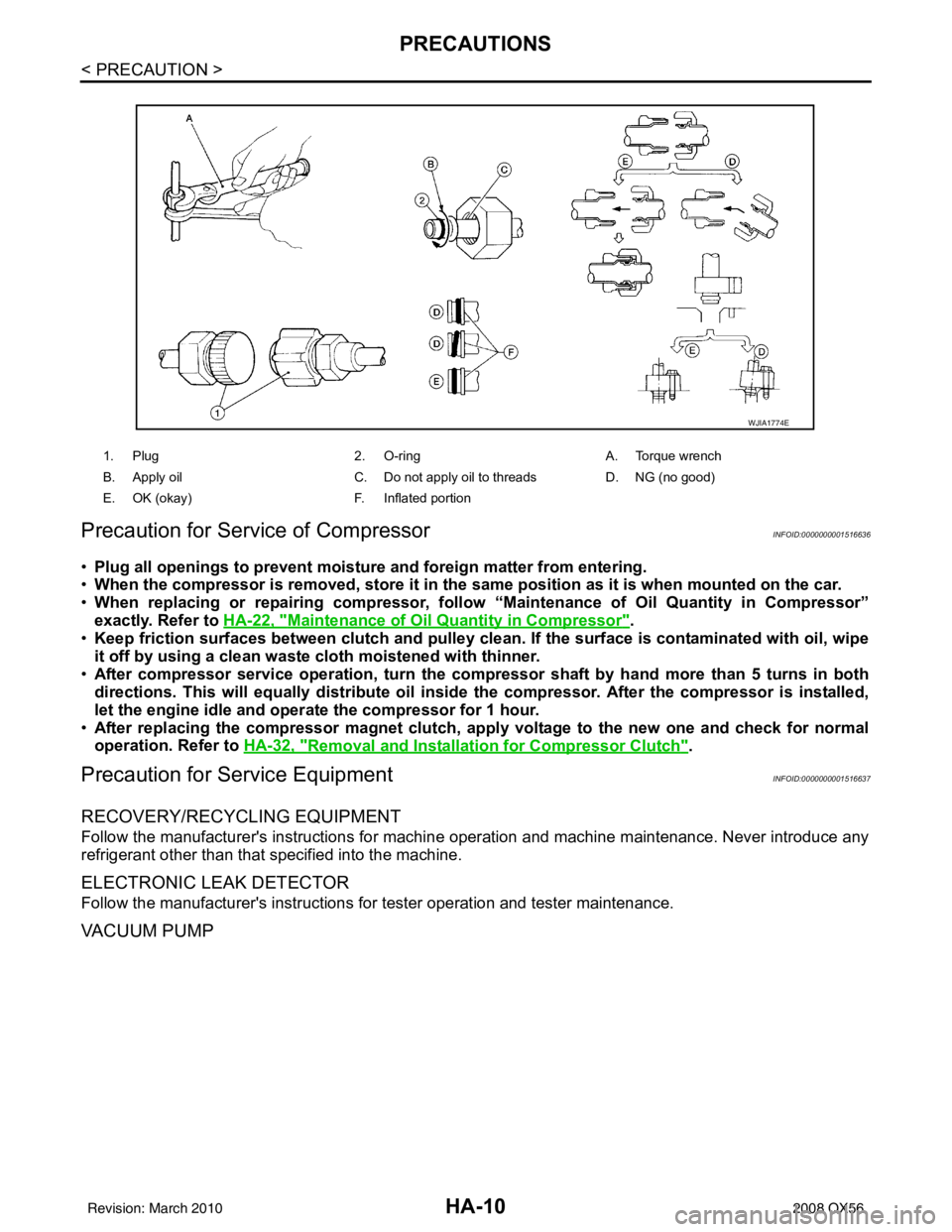
1. Plug 2. O-ring A. Torque wrench
B. Apply oil C. Do not apply oil to threads D. NG (no good)
E. OK (okay) F. Inflated portion
WJIA1774E
Revision: March 2010 2008 QX56
Page 2224 of 4083

OIL
HA-19
< FUNCTION DIAGNOSIS >
C
D E
F
G H
J
K L
M A
B
HA
N
O P
OIL
Maintenance of Oil in CompressorINFOID:0000000001516643
The oil in the compressor circulates through the system with the refrigerant. Add oil to compressor when
replacing any component or after a large refrigerant leakage has occurred. It is important to maintain the spec-
ified amount.
If oil quantity is not maintained properly , the following malfunctions may result:
• Lack of oil: May lead to a seized compressor
• Excessive oil: Inadequate cooling (thermal exchange interference)
Revision: March 2010 2008 QX56
Page 2225 of 4083

HA-20
< ON-VEHICLE MAINTENANCE >
REFRIGERATION SYSTEM
ON-VEHICLE MAINTENANCE
REFRIGERATION SYSTEM
HFC-134a (R-134a) Service ProcedureINFOID:0000000001516644
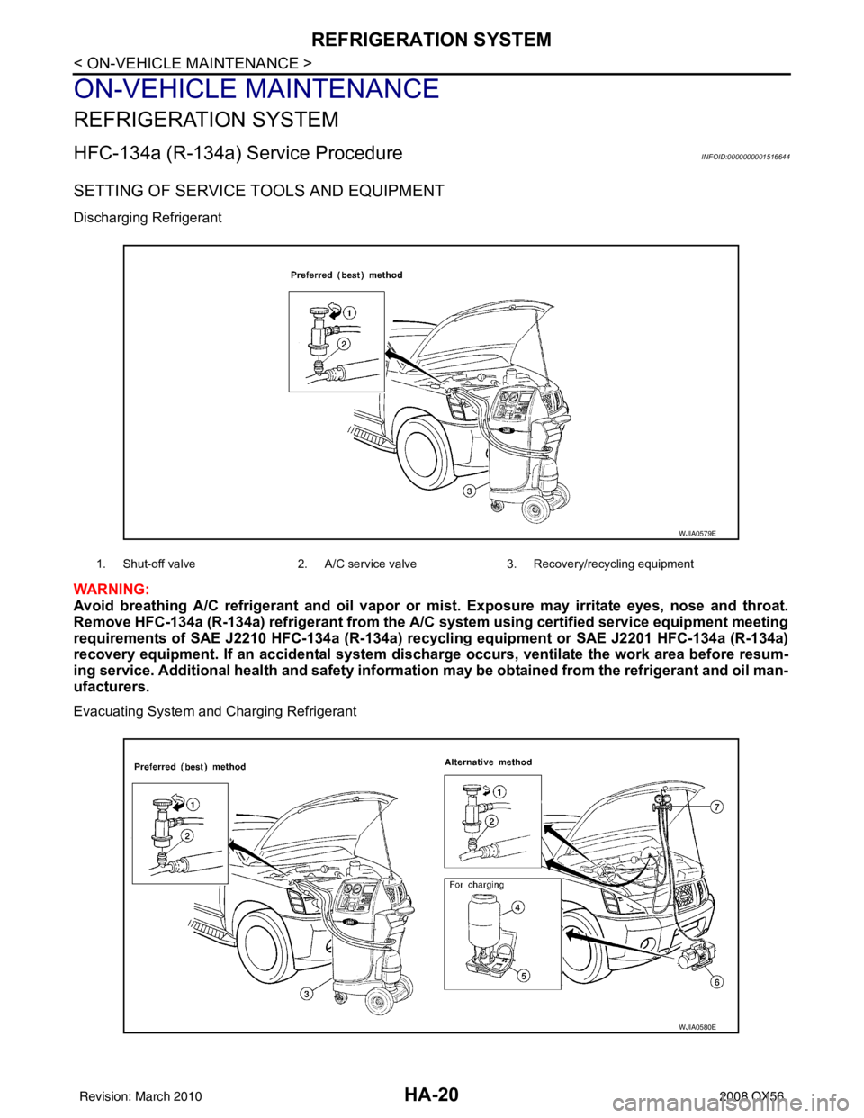
SETTING OF SERVICE TOOLS AND EQUIPMENT
Discharging Refrigerant
WARNING:
Avoid breathing A/C refrigerant and oil vapor or mist. Exposure may irritate eyes, nose and throat.
Remove HFC-134a (R-134a) refrigerant from the A/C system using certified service equipment meeting
requirements of SAE J2210 HFC-134a (R-134a) recycling equipment or SAE J2201 HFC-134a (R-134a)
recovery equipment. If an accident al system discharge occurs, ventilate the work area before resum-
ing service. Additional health and safety information may be obtained from the refrigerant and oil man-
ufacturers.
Evacuating System and Charging Refrigerant
1. Shut-off valve 2. A/C service valve 3. Recovery/recycling equipment
WJIA0579E
WJIA0580E
Revision: March 2010 2008 QX56
Page 2226 of 4083

REFRIGERATION SYSTEMHA-21
< ON-VEHICLE MAINTENANCE >
C
DE
F
G H
J
K L
M A
B
HA
N
O P
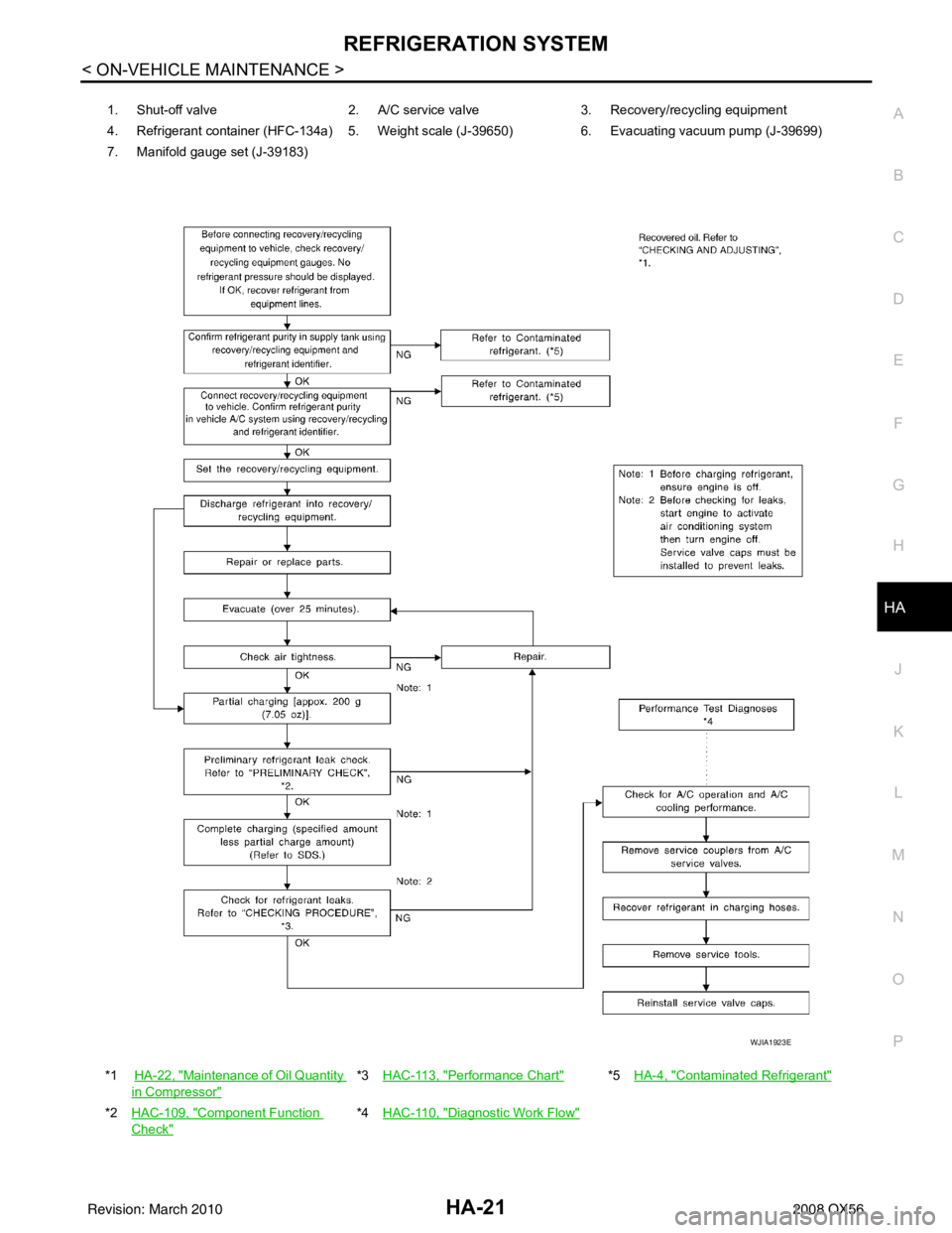
1. Shut-off valve 2. A/C service valve3. Recovery/recycling equipment
4. Refrigerant container (HFC-134a) 5. Weight scale (J-39650) 6. Evacuating vacuum pump (J-39699)
7. Manifold gauge set (J-39183)
*1 HA-22, "
Maintenance of Oil Quantity
in Compressor"
*3HAC-113, "Performance Chart"*5 HA-4, "Contaminated Refrigerant"
*2HAC-109, "Component Function
Check"
*4HAC-110, "Diagnostic Work Flow"
WJIA1923E
Revision: March 2010 2008 QX56