2008 INFINITI QX56 maintenance
[x] Cancel search: maintenancePage 1821 of 4083
EM-18
< ON-VEHICLE MAINTENANCE >
CAMSHAFT VALVE CLEARANCE
CAMSHAFT VALVE CLEARANCE
Valve ClearanceINFOID:0000000001538810
INSPECTION
NOTE:
Perform the following inspection after removal, installation or replacement of camshaft or valve-related parts,
or if there are unusual engine conditions due to changes in valve clearance over time (starting, idling, and/or
noise).
1. Warm up the engine. Then stop the engine.
2. Remove the engine room cover. Refer to EM-24, "
Removal and Installation".
3. Remove the air cleaner and air duct assembly. Refer to EM-25, "
Removal and Installation".
4. Remove the RH bank and LH bank rocker covers using power tool. Refer to EM-38, "
Removal and Instal-
lation".
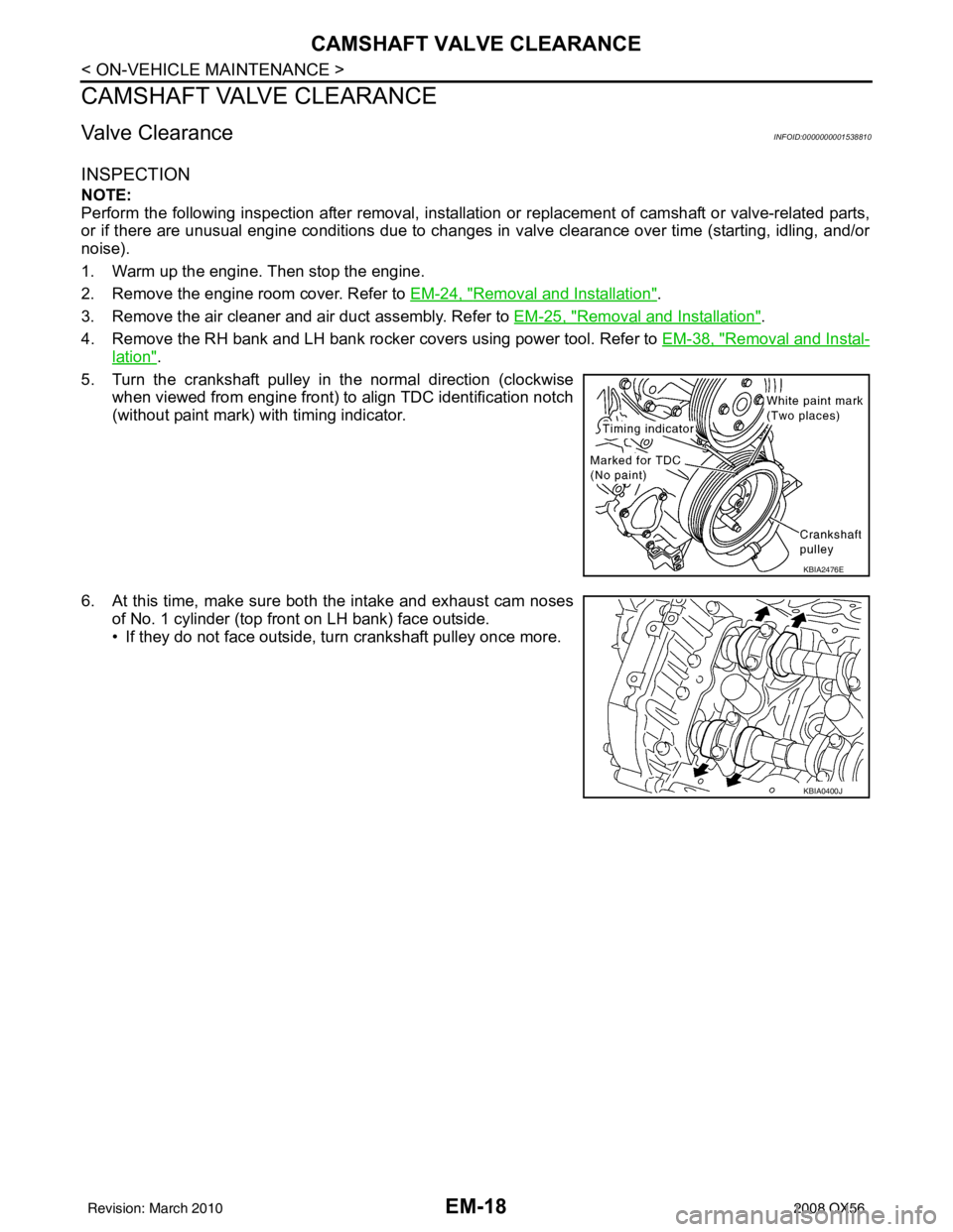
5. Turn the crankshaft pulley in the normal direction (clockwise when viewed from engine front) to align TDC identification notch
(without paint mark) with timing indicator.
6. At this time, make sure both the intake and exhaust cam noses of No. 1 cylinder (top front on LH bank) face outside.
• If they do not face outside, turn crankshaft pulley once more.
KBIA2476E
KBIA0400J
Revision: March 2010 2008 QX56
Page 1822 of 4083
CAMSHAFT VALVE CLEARANCEEM-19
< ON-VEHICLE MAINTENANCE >
C
DE
F
G H
I
J
K L
M A
EM
NP
O
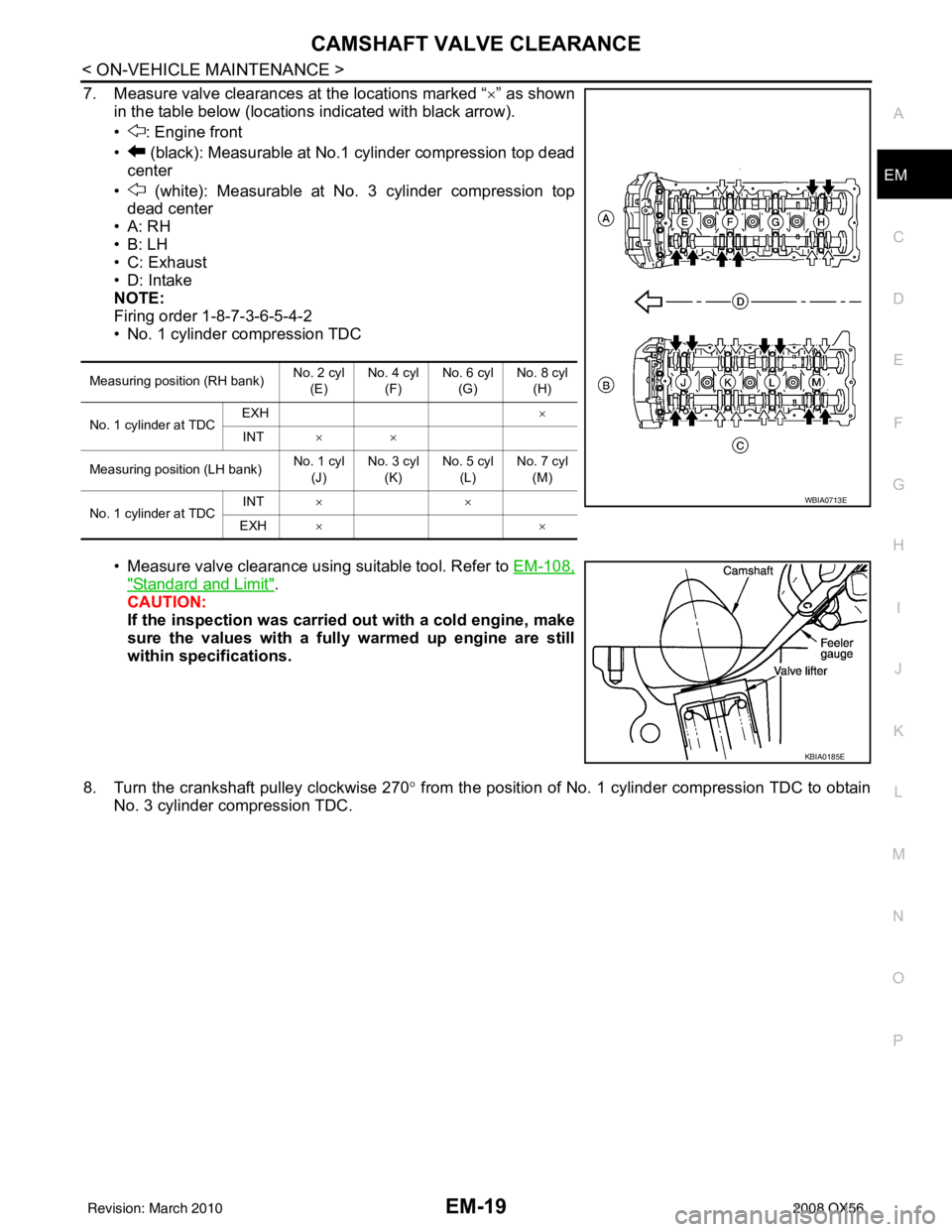
7. Measure valve clearances at the locations marked “×
” as shown
in the table below (locations indicated with black arrow).
• : Engine front
• (black): Measurable at No.1 cylinder compression top dead center
• (white): Measurable at No. 3 cylinder compression top dead center
•A: RH
•B: LH
• C: Exhaust
• D: Intake
NOTE:
Firing order 1-8-7-3-6-5-4-2
• No. 1 cylinder compression TDC
• Measure valve clearance using suitable tool. Refer to EM-108,
"Standard and Limit".
CAUTION:
If the inspection was carried out with a cold engine, make
sure the values with a fully warmed up engine are still
within specifications.
8. Turn the crankshaft pulley clockwise 270 ° from the position of No. 1 cylinder compression TDC to obtain
No. 3 cylinder compression TDC.
Measuring position (RH bank) No. 2 cyl
(E) No. 4 cyl
(F) No. 6 cyl
(G) No. 8 cyl
(H)
No. 1 cylinder at TDC EXH
×
INT ××
Measuring position (LH bank) No. 1 cyl
(J) No. 3 cyl
(K) No. 5 cyl
(L) No. 7 cyl
(M)
No. 1 cylinder at TDC INT
××
EXH ××
WBIA0713E
KBIA0185E
Revision: March 2010 2008 QX56
Page 1823 of 4083
EM-20
< ON-VEHICLE MAINTENANCE >
CAMSHAFT VALVE CLEARANCE
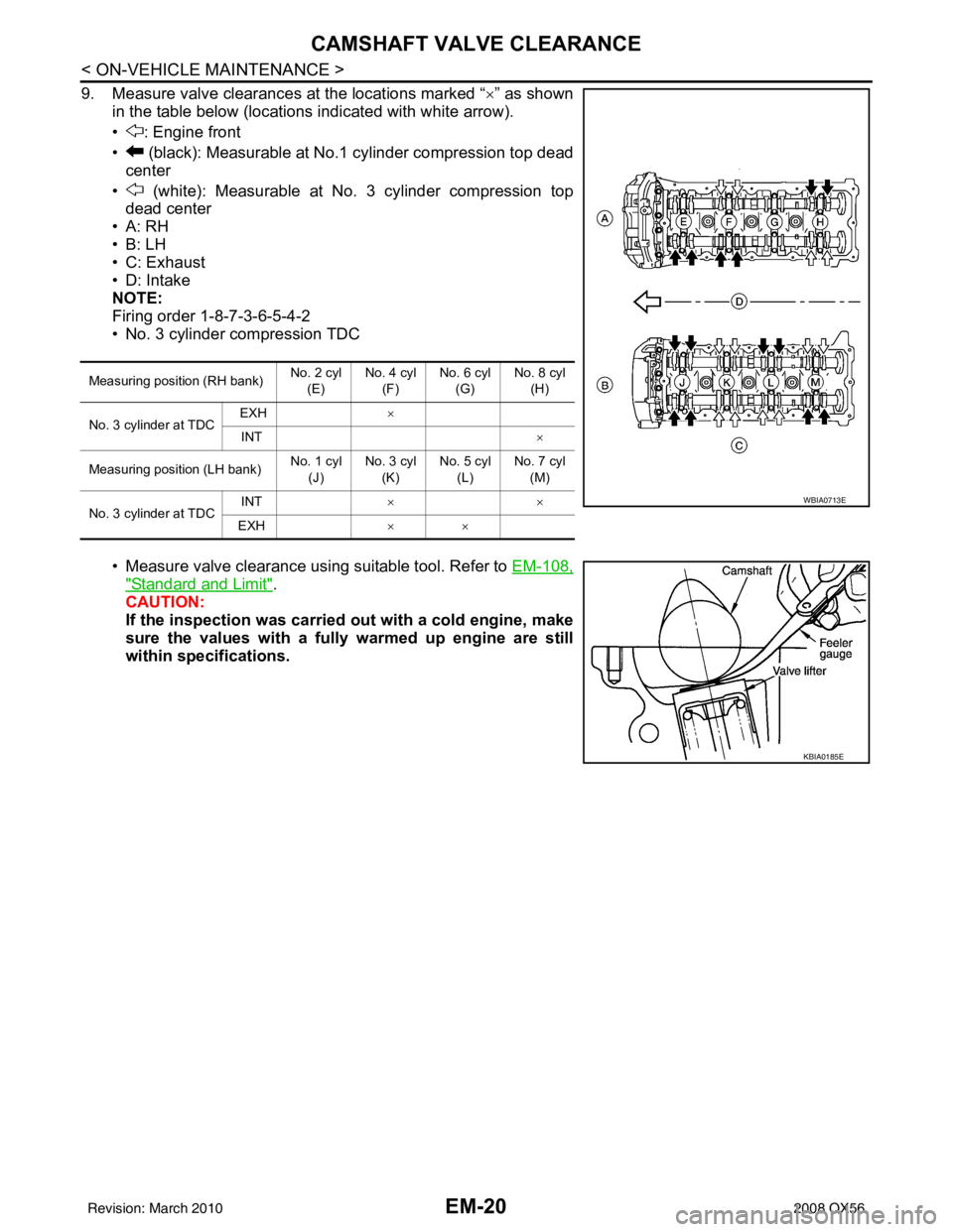
9. Measure valve clearances at the locations marked “×” as shown
in the table below (locations indicated with white arrow).
• : Engine front
• (black): Measurable at No.1 cylinder compression top dead center
• (white): Measurable at No. 3 cylinder compression top dead center
•A: RH
•B: LH
• C: Exhaust
•D: Intake
NOTE:
Firing order 1-8-7-3-6-5-4-2
• No. 3 cylinder compression TDC
• Measure valve clearance using suitable tool. Refer to EM-108,
"Standard and Limit".
CAUTION:
If the inspection was carried out with a cold engine, make
sure the values with a fully warmed up engine are still
within specifications.
Measuring position (RH bank) No. 2 cyl
(E) No. 4 cyl
(F) No. 6 cyl
(G) No. 8 cyl
(H)
No. 3 cylinder at TDC EXH
×
INT ×
Measuring position (LH bank) No. 1 cyl
(J) No. 3 cyl
(K) No. 5 cyl
(L) No. 7 cyl
(M)
No. 3 cylinder at TDC INT
××
EXH ××
WBIA0713E
KBIA0185E
Revision: March 2010 2008 QX56
Page 1824 of 4083
CAMSHAFT VALVE CLEARANCEEM-21
< ON-VEHICLE MAINTENANCE >
C
DE
F
G H
I
J
K L
M A
EM
NP
O
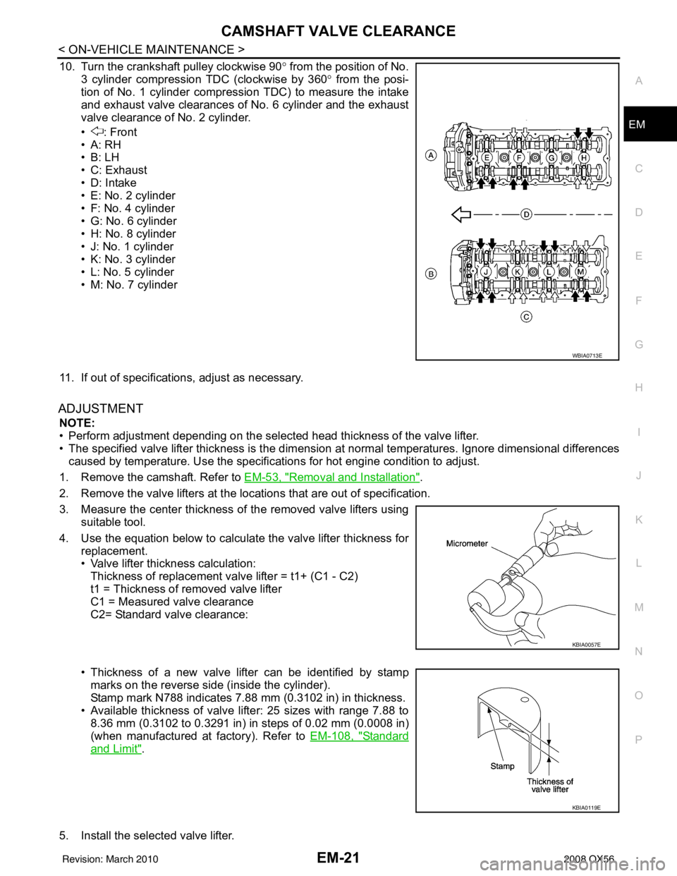
10. Turn the crankshaft pulley clockwise 90°
from the position of No.
3 cylinder compression TDC (clockwise by 360 ° from the posi-
tion of No. 1 cylinder compression TDC) to measure the intake
and exhaust valve clearances of No. 6 cylinder and the exhaust
valve clearance of No. 2 cylinder.
• : Front
•A: RH
•B: LH
• C: Exhaust
• D: Intake
• E: No. 2 cylinder
• F: No. 4 cylinder
• G: No. 6 cylinder
• H: No. 8 cylinder
• J: No. 1 cylinder
• K: No. 3 cylinder
• L: No. 5 cylinder
• M: No. 7 cylinder
11. If out of specifications, adjust as necessary.
ADJUSTMENT
NOTE:
• Perform adjustment depending on the selected head thickness of the valve lifter.
• The specified valve lifter thickness is the dimension at normal temperatures. Ignore dimensional differences
caused by temperature. Us e the specifications for hot engine condition to adjust.
1. Remove the camshaft. Refer to EM-53, "
Removal and Installation".
2. Remove the valve lifters at the locations that are out of specification.
3. Measure the center thickness of the removed valve lifters using suitable tool.
4. Use the equation below to calculate the valve lifter thickness for replacement.
• Valve lifter thickness calculation:Thickness of replacement valve lifter = t1+ (C1 - C2)
t1 = Thickness of removed valve lifter
C1 = Measured valve clearance
C2= Standard valve clearance:
• Thickness of a new valve lifter can be identified by stamp marks on the reverse side (inside the cylinder).
Stamp mark N788 indicates 7.88 mm (0.3102 in) in thickness.
• Available thickness of valve lifter: 25 sizes with range 7.88 to 8.36 mm (0.3102 to 0.3291 in) in steps of 0.02 mm (0.0008 in)
(when manufactured at factory). Refer to EM-108, "
Standard
and Limit".
5. Install the selected valve lifter.
WBIA0713E
KBIA0057E
KBIA0119E
Revision: March 2010 2008 QX56
Page 1825 of 4083

EM-22
< ON-VEHICLE MAINTENANCE >
CAMSHAFT VALVE CLEARANCE
6. Install the camshaft.
7. Manually turn the crankshaft pulley a few turns.
8. Make sure the valve clearances for a cold engine are within specifications. Refer to EM-108, "
Standard
and Limit".
9. After completing the repair, check the valve clearanc es again with the specifications for a warmed engine.
Make sure the values are wit hin specifications. Refer to EM-108, "
Standard and Limit".
Revision: March 2010 2008 QX56
Page 1826 of 4083
COMPRESSION PRESSUREEM-23
< ON-VEHICLE MAINTENANCE >
C
DE
F
G H
I
J
K L
M A
EM
NP
O
COMPRESSION PRESSURE
Checking Compression PressureINFOID:0000000001538811
1. Warm up the engine thoroughly. Then stop the engine.
2. Release the fuel pressure. Refer to EC-494, "
Fuel Pressure Check".
CAUTION:
If CONSULT-III is not used to release fuel pressure leave the fuel pump fuse disconnected until
step 7.
3. Remove the spark plug from each cylinder. Refer to EM-16, "
Removal and Installation".
4. Connect the engine tachometer (not required in use of CONSULT-III).
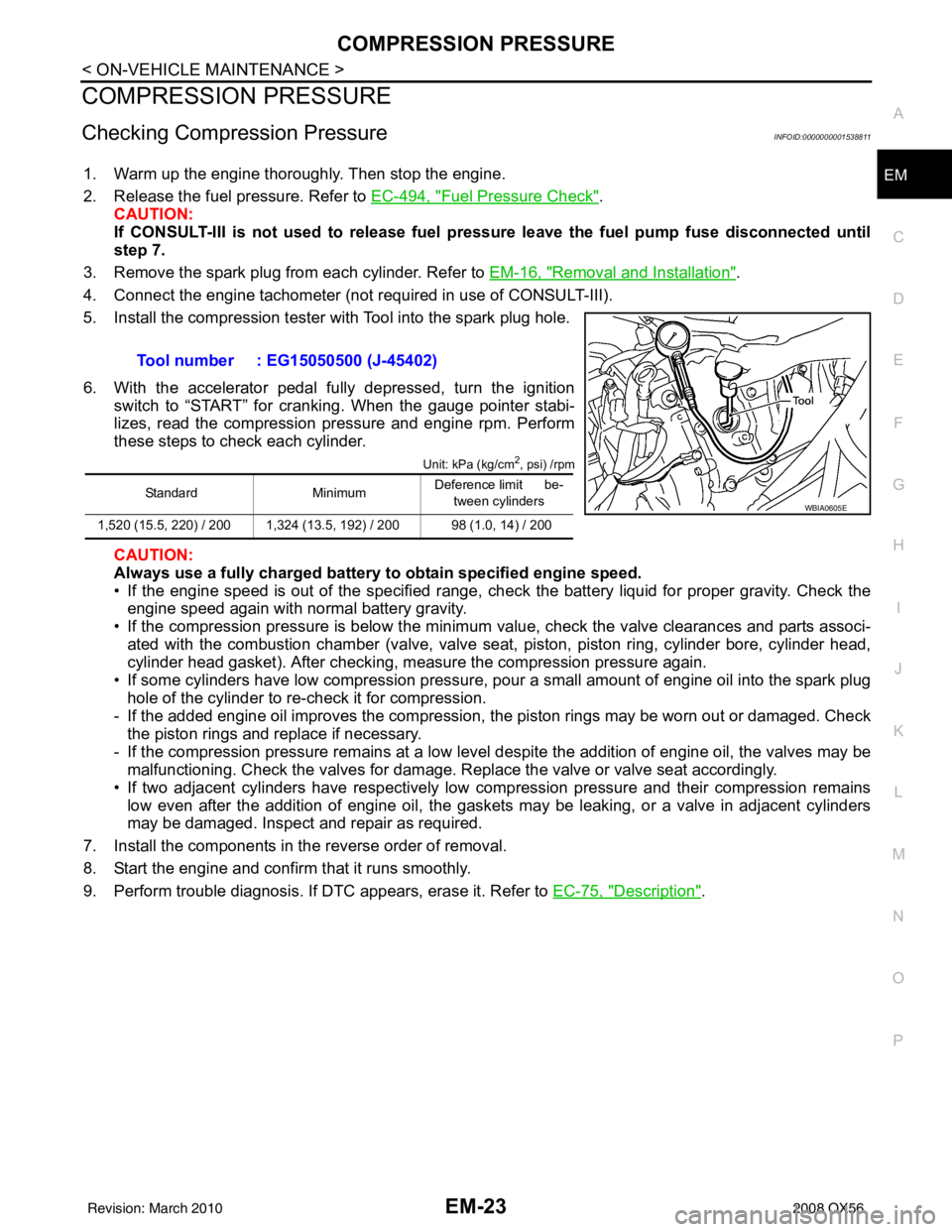
5. Install the compression tester with Tool into the spark plug hole.
6. With the accelerator pedal fully depressed, turn the ignition switch to “START” for cranking. When the gauge pointer stabi-
lizes, read the compression pressure and engine rpm. Perform
these steps to check each cylinder.
Unit: kPa (kg/cm2, psi) /rpm
CAUTION:
Always use a fully charged battery to obtain specified engine speed.
• If the engine speed is out of the specified range, check the battery liquid for proper gravity. Check the engine speed again with normal battery gravity.
• If the compression pressure is below the minimum value, check the valve clearances and parts associ-
ated with the combustion chamber (valve, valve seat , piston, piston ring, cylinder bore, cylinder head,
cylinder head gasket). After checking, measure the compression pressure again.
• If some cylinders have low compression pressure, pour a small amount of engine oil into the spark plug hole of the cylinder to re-check it for compression.
- If the added engine oil improves the compression, t he piston rings may be worn out or damaged. Check
the piston rings and replace if necessary.
- If the compression pressure remains at a low level despite the addition of engine oil, the valves may be malfunctioning. Check the valves for damage. Replace the valve or valve seat accordingly.
• If two adjacent cylinders have respectively low compression pressure and their compression remains low even after the addition of engine oil, the gaskets may be leaking, or a valve in adjacent cylinders
may be damaged. Inspect and repair as required.
7. Install the components in the reverse order of removal.
8. Start the engine and confirm that it runs smoothly.
9. Perform trouble diagnosis. If DTC appears, erase it. Refer to EC-75, "
Description".
Tool number : EG15050500 (J-45402)
Standard
MinimumDeference limit be-
tween cylinders
1,520 (15.5, 220) / 200 1,324 (13.5, 192) / 200 98 (1.0, 14) / 200WBIA0605E
Revision: March 2010 2008 QX56
Page 1922 of 4083

EX-1
ENGINE
C
DE
F
G H
I
J
K L
M
SECTION EX
A
EX
N
O P
CONTENTS
EXHAUST SYSTEM
PRECAUTION ....... ........................................2
PRECAUTIONS .............................................. .....2
Precaution for Supplemental Restraint System
(SRS) "AIR BAG" and "SEAT BELT PRE-TEN-
SIONER" ............................................................. ......
2
Precaution Necessary for Steering Wheel Rota-
tion After Battery Disconnect ............................... ......
2
Precaution for Liquid Gasket .....................................3
PREPARATION ............................................4
PREPARATION ..................................................4
Special Service Tool ............................................ .....4
Commercial Service Tool .........................................4
ON-VEHICLE MAINTENANCE .....................5
EXHAUST SYSTEM ...........................................5
Checking Exhaust System ................................... .....5
ON-VEHICLE REPAIR ..................................6
EXHAUST SYSTEM ...........................................6
Removal and Installation ..................................... .....6
Revision: March 2010 2008 QX56
Page 1923 of 4083
EX-2
< PRECAUTION >
PRECAUTIONS
PRECAUTION
PRECAUTIONS
Precaution for Supplemental Restraint System (SRS) "AIR BAG" and "SEAT BELT
PRE-TENSIONER"
INFOID:0000000004857579
The Supplemental Restraint System such as “A IR BAG” and “SEAT BELT PRE-TENSIONER”, used along
with a front seat belt, helps to reduce the risk or severity of injury to the driver and front passenger for certain
types of collision. This system includes seat belt switch inputs and dual stage front air bag modules. The SRS
system uses the seat belt switches to determine the front air bag deployment, and may only deploy one front
air bag, depending on the severity of a collision and w hether the front occupants are belted or unbelted.
Information necessary to service the system safely is included in the SR and SB section of this Service Man-
ual.
WARNING:
• To avoid rendering the SRS inopera tive, which could increase the risk of personal injury or death in
the event of a collision which would result in air bag inflation, all maintenance must be performed by
an authorized NISSAN/INFINITI dealer.
• Improper maintenance, including in correct removal and installation of the SRS, can lead to personal
injury caused by unintent ional activation of the system. For re moval of Spiral Cable and Air Bag
Module, see the SR section.
• Do not use electrical test equipmen t on any circuit related to the SRS unless instructed to in this
Service Manual. SRS wiring harn esses can be identified by yellow and/or orange harnesses or har-
ness connectors.
PRECAUTIONS WHEN USING POWER TOOLS (AIR OR ELECTRIC) AND HAMMERS
WARNING:
• When working near the Airbag Diagnosis Sensor Unit or other Airbag System sensors with the Igni-
tion ON or engine running, DO NOT use air or electri c power tools or strike near the sensor(s) with a
hammer. Heavy vibration could activate the sensor( s) and deploy the air bag(s), possibly causing
serious injury.
• When using air or electric power tools or hammers , always switch the Ignition OFF, disconnect the
battery, and wait at least 3 minu tes before performing any service.
Precaution Necessary for Steering W heel Rotation After Battery Disconnect
INFOID:0000000004857585
NOTE:
• This Procedure is applied only to models with Intelligent Key system and NATS (NISSAN ANTI-THEFT SYS-
TEM).
• Remove and install all control units after disconnecting both battery cables with the ignition knob in the
″LOCK ″ position.
• Always use CONSULT-III to perform self-diagnosis as a part of each function inspection after finishing work.
If DTC is detected, perform trouble diagnosis according to self-diagnostic results.
For models equipped with the Intelligent Key system and NATS, an electrically controlled steering lock mech-
anism is adopted on the key cylinder.
For this reason, if the battery is disconnected or if the battery is discharged, the steering wheel will lock and
steering wheel rotation will become impossible.
If steering wheel rotation is required when battery pow er is interrupted, follow the procedure below before
starting the repair operation.
OPERATION PROCEDURE
1. Connect both battery cables. NOTE:
Supply power using jumper cables if battery is discharged.
2. Use the Intelligent Key or mechanical key to turn the ignition switch to the ″ACC ″ position. At this time, the
steering lock will be released.
3. Disconnect both battery cables. The steering lock will remain released and the steering wheel can be rotated.
4. Perform the necessary repair operation.
Revision: March 2010 2008 QX56