2008 INFINITI QX56 low oil pressure
[x] Cancel search: low oil pressurePage 2816 of 4083

PG
HARNESSPG-49
< COMPONENT DIAGNOSIS >
C
DE
F
G H
I
J
K L
B A
O P
N
C3 F7 GR/3
: Ignition coil No. 4 (with power
transistor) F1 F60 GR/2 : Neutral-4LO switch
C3 F8 GR/3 : Ignition coil No. 6 (with power
transistor)
D5 F61 G/2: Intake valve timing control solenoid valve
(bank 1)
E2 F9 G/10 : A/T assembly D5 F62 G/2: Intake valve timing control position sensor
(bank 1)
C3 F10 — : Engine ground C4 F63 G/2: Intake valve timing control solenoid valve
(bank 2)
D3 F11 B/3 : Crankshaft position sensor (POS) C4 F64 G/2 : Intake valve timing control position sensor
(bank 2)
E1 F12 G/4 : Heated oxygen sensor 2 (bank2) E3 F65 GR/4 : Air fuel ratio (A/F) sensor 1 (bank1)
F2 F13 G/4 : Heated oxygen sensor 2 (bank1) C2 F68 B/2 : Water valve
B2 F14 W/24 : To E5 C3 F101 B/6 : To F26
D4 F15 L/2 : EVAP canister purge volume control
solenoid valve C3 F102 B/2 : Knock sensor (bank 1)
E5 F16 — : Engine ground C3 F103 GR/2 : Engine coolant temperature sensor
C4 F18 GR/2 : Fuel injector No. 2 C3 F104 B/2 : Knock sensor (bank 2)
D4 F20 GR/2 : Fuel injector No. 4
F4 F21 W/2 : Condenser-1
D3 F22 GR/2 : Fuel injector No. 6
D4 F23 B/3 : Camshaft position sensor (phase)
D4 F26 B/6 : To F101
E3 F27 B/1 : Starter motor
D4 F30 GR/2 : Fuel injector No. 1
D3 F31 GR/2 : Fuel injector No. 8
B2 F32 W/16 : To E2
C2 F33 W/16 : To E19
C2 F34 W/2 : To E39
B3 F39 — : Fusible link (battery)
D4 F41 GR/2 : Fuel injector No. 3
D4 F42 GR/2 : Fuel injector No. 5
D3 F45 GR/2 : Fuel injector No. 7
B4 F46 B/3 : Power steering pressure sensor
E4 F47 GR/3 : Ignition coil No. 1 (with power
transistor)
E4 F48 GR/3 : Ignition coil No. 3 (with power
transistor)
E4 F49 GR/3 : Ignition coil No. 5 (with power
transistor)
D4 F50 B/6 : Electric throttle control actuator
E4 F51 GR/3 : Ignition coil No. 7 (with power
transistor)
D2 F52 GR/3 : Ignition coil No. 8 (with power
transistor)
E5 F53 B/6 : Mass air flow sensor
B2 F54 B/81 : ECM
F1 F55 B/2 : ATP switch
Revision: March 2010 2008 QX56
Page 3051 of 4083
RSU-12
< REMOVAL AND INSTALLATION >
REAR SUSPENSION MEMBER
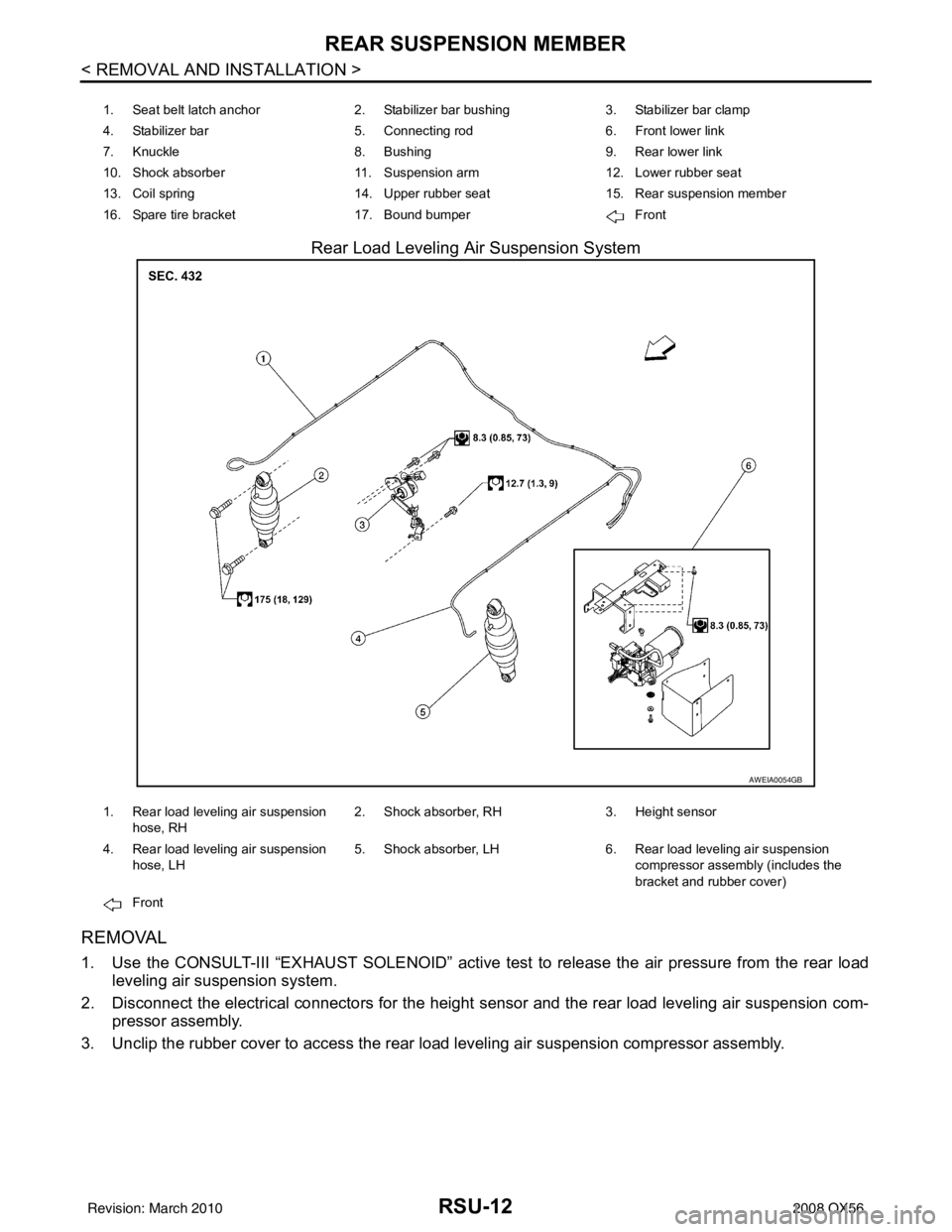
Rear Load Leveling Air Suspension System
REMOVAL
1. Use the CONSULT-III “EXHAUST SOLENOID” active test to release the air pressure from the rear load
leveling air suspension system.
2. Disconnect the electrical connectors for the height sensor and the rear load leveling air suspension com-
pressor assembly.
3. Unclip the rubber cover to access the rear load leveling air suspension compressor assembly.
1. Seat belt latch anchor 2. Stabilizer bar bushing3. Stabilizer bar clamp
4. Stabilizer bar 5. Connecting rod 6. Front lower link
7. Knuckle 8. Bushing9. Rear lower link
10. Shock absorber 11. Suspension arm12. Lower rubber seat
13. Coil spring 14. Upper rubber seat15. Rear suspension member
16. Spare tire bracket 17. Bound bumper Front
AWEIA0054GB
1. Rear load leveling air suspension
hose, RH 2. Shock absorber, RH
3. Height sensor
4. Rear load leveling air suspension hose, LH 5. Shock absorber, LH
6. Rear load leveling air suspension
compressor assembly (includes the
bracket and rubber cover)
Front
Revision: March 2010 2008 QX56
Page 3059 of 4083
RSU-20
< REMOVAL AND INSTALLATION >
REAR LOWER LINK & COIL SPRING
REAR LOWER LINK & COIL SPRING
Removal and InstallationINFOID:0000000004900761
REMOVAL
1. Remove the wheel and tire assembly using power tool. Refer to WT-48, "Rotation" .
2. Use CONSULT-III "EXHAUST SOLENOID" active test to release the air pressure from the rear load level-
ing air suspension system.
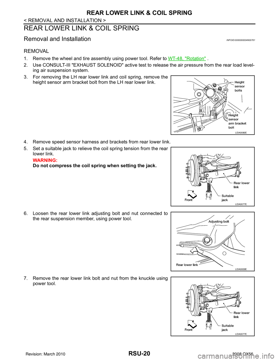
3. For removing the LH rear lower link and coil spring, remove the height sensor arm bracket bolt from the LH rear lower link.
4. Remove speed sensor harness and brackets from rear lower link.
5. Set a suitable jack to relieve the coil spring tension from the rear lower link.
WARNING:
Do not compress the coil sp ring when setting the jack.
6. Loosen the rear lower link adjusting bolt and nut connected to the rear suspension member, using power tool.
7. Remove the rear lower link bolt and nut from the knuckle using power tool.
LEIA0080E
LEIA0077E
LEIA0009E
LEIA0077E
Revision: March 2010 2008 QX56
Page 3093 of 4083
SCS-10
< COMPONENT DIAGNOSIS >
C1802 COMPRESSOR RELAY
C1802 COMPRESSOR RELAY
DescriptionINFOID:0000000001731963
The compressor motor relay is controlled by the suspension control unit. The suspension control unit supplies
voltage to the coil side of the relay to activate it. T he compressor motor relay, when activated, supplies power
to the suspension air compressor.
DTC LogicINFOID:0000000001731964
DTC DETECTION LOGIC
Diagnosis ProcedureINFOID:0000000001731965
1.CHECK COMPRESSOR MOTOR RELAY OPERATION
CAUTION:
The "COMPRESSOR" active test will remain ON until it is turned off using CONSULT-III. Allowing the
compressor to run for an extended period of time may cause damage to the air levelizer system com-
ponents due to excessive air pressure.
CONSULT-III
1. Turn ignition ON.
2. Select "COMPRESSOR" of AIR LEVELIZER active test items.
3. While operating test item, check that the suspension air compressor turns ON.
Does the suspension air compressor operate properly?
YES >> Compressor motor relay and suspension air compressor are operating normally.
NO >> Refer to SCS-20, "
Diagnosis Procedure"
DTCDisplay contents of CON-
SULT-III Diagnostic item is detected when ...
Probable malfunction location
C1802 COMPRESSOR RELAY • Driving transistor for the compressor
relay is
OFF and monitor voltage continues at a high
level for more than 10 seconds.
• Driving transistor for the compressor relay is
ON and monitor voltage continues at a low
level for more than 5 seconds. Compressor motor relay. Refer to
SCS-20,
"Component Function Check"
ON : Compressor turns ON
OFF : Compressor turns OFF
Revision: March 2010 2008 QX56
Page 3095 of 4083
SCS-12
< COMPONENT DIAGNOSIS >
C1804 HEIGHT ADJUSTING MALFUNCTION (COMPRESSOR)
C1804 HEIGHT ADJUSTING MA LFUNCTION (COMPRESSOR)
DescriptionINFOID:0000000001731969
The compressor motor relay is controlled by the sus pension control unit. The suspension control unit supplies
voltage to the coil side of the relay to activate it. T he compressor motor relay, when activated, supplies power
to the suspension air compressor.
DTC LogicINFOID:0000000001731970
DTC DETECTION LOGIC
Diagnosis ProcedureINFOID:0000000001731971
1.CHECK COMPRESSOR MOTOR RELAY OPERATION
CAUTION:
The "COMPRESSOR" active test will remain ON until it is turned off using CONSULT-III. Allowing the
compressor to run for an extended period of time may cause damage to the air levelizer system com-
ponents due to excessive air pressure.
CONSULT-III
1. Turn ignition ON.
2. Select "COMPRESSOR" of AIR LEVELIZER active test items.
3. While operating test item, check that the suspension air compressor turns ON.
Does the suspension air compressor operate properly?
YES >> Compressor motor relay and suspension air compressor are operating normally.
NO >> Refer to SCS-20, "
Diagnosis Procedure"
DTCDisplay contents of CON-
SULT-III Diagnostic item is detected when ...
Probable malfunction location
C1804 VEHICLE HEIGHT AD-
JUSTING MALFUNC-
TION (COMPRESSOR) Continuous compressor relay ON time is more
than 120 seconds.
Compressor motor relay. Refer to
SCS-20,
"Component Function Check"
ON : Compressor turns ON
OFF : Compressor turns OFF
Revision: March 2010 2008 QX56
Page 3311 of 4083
![INFINITI QX56 2008 Factory Service Manual IPDM E/R (INTELLIGENT POWER DISTRIBUTION MODULE ENGINE ROOM)
SEC-103
< ECU DIAGNOSIS > [WITH INTELLIGENT KEY SYSTEM]
C
D
E
F
G H
I
J
L
M A
B
SEC
N
O P
41 Y/B Hood switch Input —Hood closed OFF
0V
Ho INFINITI QX56 2008 Factory Service Manual IPDM E/R (INTELLIGENT POWER DISTRIBUTION MODULE ENGINE ROOM)
SEC-103
< ECU DIAGNOSIS > [WITH INTELLIGENT KEY SYSTEM]
C
D
E
F
G H
I
J
L
M A
B
SEC
N
O P
41 Y/B Hood switch Input —Hood closed OFF
0V
Ho](/manual-img/42/57030/w960_57030-3310.png)
IPDM E/R (INTELLIGENT POWER DISTRIBUTION MODULE ENGINE ROOM)
SEC-103
< ECU DIAGNOSIS > [WITH INTELLIGENT KEY SYSTEM]
C
D
E
F
G H
I
J
L
M A
B
SEC
N
O P
41 Y/B Hood switch Input —Hood closed OFF
0V
Hood open ON Battery voltage
42 GR Oil pressure switch Input — Engine running
Battery voltage
Engine stopped 0V
43 L/Y Wiper auto stop signal Input ON or
START Wiper switch OFF, LO, INT Battery voltage
44 BR Daytime light relay
control Input ONDaytime light system active
0V
Daytime light system inactive Battery voltage
45 G/W Horn relay control Input ON When door locks are operated
using keyfob or Intelligent Key
(OFF
→ ON)* Battery voltage
→ 0V
46 GR Fuel pump relay con-
trol
Input —Ignition switch ON or START
0V
Ignition switch OFF or ACC Battery voltage
47 O Throttle control motor
relay control
Input —Ignition switch ON or START
0V
Ignition switch OFF or ACC Battery voltage
48 B/R Starter relay (trans-
mission range switch) Input
ON or
START A/T shift selector lever in "P"
or "N"
0V
A/T shift selector lever any
other position Battery voltage
49 R/L Trailer tow relay Output ON Lighting
switch must
be in the 1st
positionOFF
0V
ON Battery voltage
50 W/R Front fog lamp (LH) Output ON or
START Lighting
switch must
be in the 2nd
position
(LOW beam
is ON) and
the front fog
lamp switch OFF
0V
ON Battery voltage
51 W/R Front fog lamp (RH) Output ON or
START Lighting
switch must
be in the 2nd
position
(LOW beam
is ON) and
the front fog
lamp switch OFF
0V
ON Battery voltage
52 L LH low beam head-
lamp Output — Lighting switch in 2nd position Battery voltage
54 R/Y RH low beam head-
lamp
Output — Lighting switch in 2nd position Battery voltage
55 G LH high beam head-
lamp
Output —Lighting switch in 2nd position
and placed in HIGH or PASS
position
Battery voltage
56 L/W RH high beam head-
lamp Output —Lighting switch in 2nd position
and placed in HIGH or PASS
position Battery voltage
Te r m i n a l
Wire
col or Si
gn
al nameSignal
input/
output Measuring condition
Reference value(Approx.)
Igni-
tion
switch Operation or condition
Revision: March 2010
2008 QX56
Page 3508 of 4083
POWER STEERING OIL PUMPST-17
< ON-VEHICLE REPAIR >
C
DE
F
H I
J
K L
M A
B
ST
N
O P
POWER STEERING OIL PUMP
On-Vehicle Inspection and ServiceINFOID:0000000004920097
CHECKING RELIEF OIL PRESSURE
CAUTION:
Before starting work, confirm belt tension is proper.
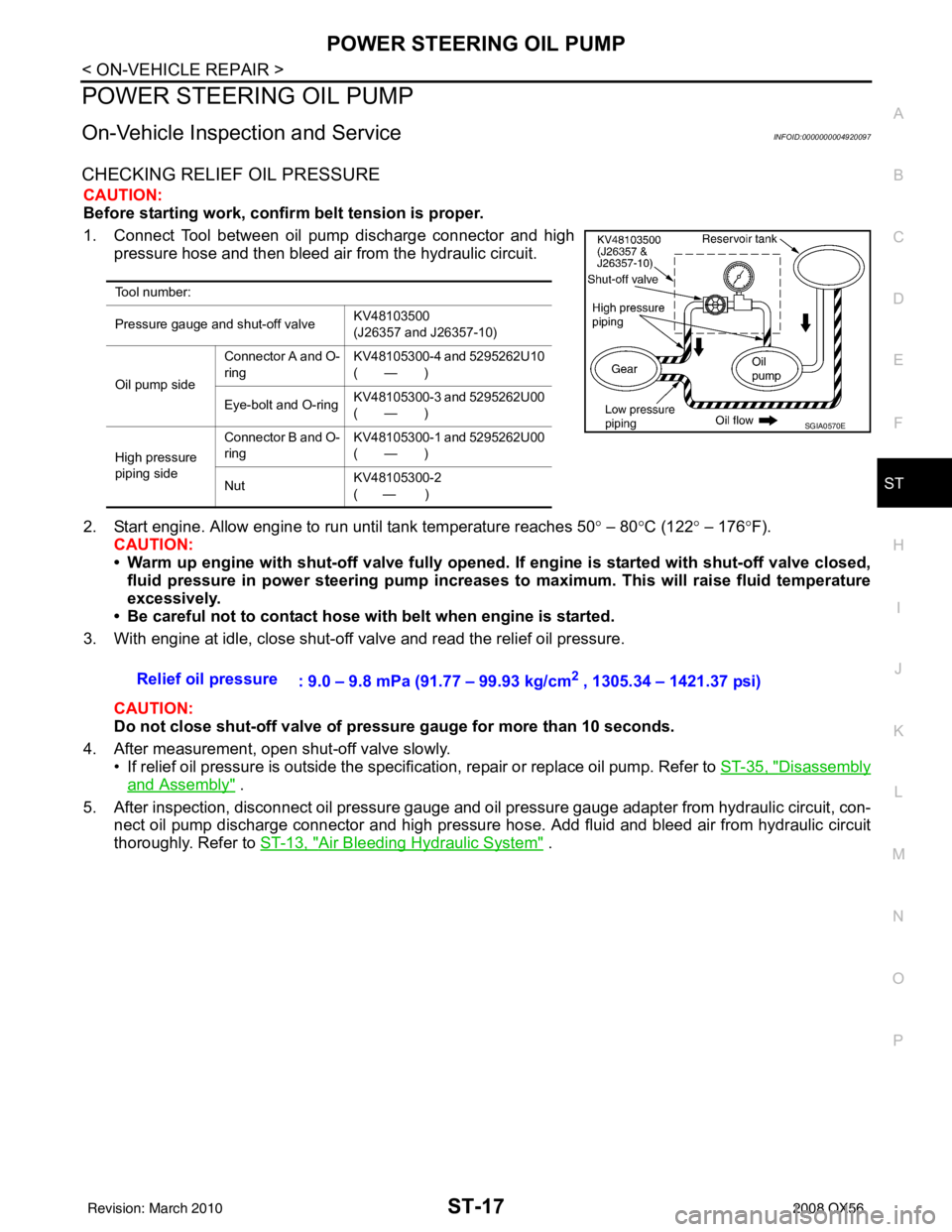
1. Connect Tool between oil pump discharge connector and high pressure hose and then bleed air from the hydraulic circuit.
2. Start engine. Allow engine to run until tank temperature reaches 50 ° – 80 °C (122° – 176°F).
CAUTION:
• Warm up engine with shut-off valve fully opened. If engine is started with shut-off valve closed,
fluid pressure in power steering pump increases to maximum. This will raise fluid temperature
excessively.
• Be careful not to contact hose with belt when engine is started.
3. With engine at idle, close shut-off valve and read the relief oil pressure.
CAUTION:
Do not close shut-off valve of pressure gauge for more than 10 seconds.
4. After measurement, open shut-off valve slowly. • If relief oil pressure is outside the specification, repair or replace oil pump. Refer to ST-35, "
Disassembly
and Assembly" .
5. After inspection, disconnect oil pressure gauge and oil pressure gauge adapter from hydraulic circuit, con-
nect oil pump discharge connector and high pressure hose. Add fluid and bleed air from hydraulic circuit
thoroughly. Refer to ST-13, "
Air Bleeding Hydraulic System" .
Tool number:
Pressure gauge and shut-off valve KV48103500
(J26357 and J26357-10)
Oil pump side Connector A and O-
ring
KV48105300-4 and 5295262U10
(—)
Eye-bolt and O-ring KV48105300-3 and 5295262U00
(—)
High pressure
piping side Connector B and O-
ring
KV48105300-1 and 5295262U00
(—)
Nut KV48105300-2
( — )
SGIA0570E
Relief oil pressure
: 9.0 – 9.8 mPa (91.77 – 99.93 kg/cm2 , 1305.34 – 1421.37 psi)
Revision: March 2010 2008 QX56
Page 3515 of 4083
ST-24
< REMOVAL AND INSTALLATION >
POWER STEERING GEAR AND LINKAGE
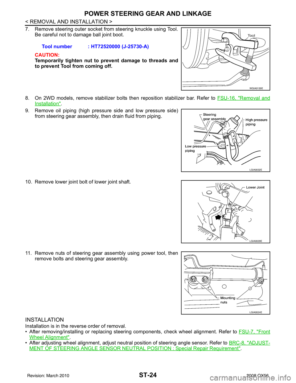
7. Remove steering outer socket from steering knuckle using Tool.Be careful not to damage ball joint boot.
CAUTION:
Temporarily tighten nut to prevent damage to threads and
to prevent Tool from coming off.
8. On 2WD models, remove stabilizer bolts then reposition stabilizer bar. Refer to FSU-16, "
Removal and
Installation".
9. Remove oil piping (high pressure side and low pressure side) from steering gear assembly, then drain fluid from piping.
10. Remove lower joint bolt of lower joint shaft.
11. Remove nuts of steering gear assembly using power tool, then remove bolts and steering gear assembly.
INSTALLATION
Installation is in the reverse order of removal.
• After removing/installing or replacing steering components, check wheel alignment. Refer to FSU-7, "
Front
Wheel Alignment".
• After adjusting wheel alignment, adjust neutral position of steering angle sensor. Refer to BRC-8, "
ADJUST-
MENT OF STEERING ANGLE SENSOR NEUTRAL POSITION : Special Repair Requirement".
Tool number : HT72520000 (J-25730-A)
WGIA0130E
LGIA0032E
LGIA0029E
LGIA0024E
Revision: March 2010
2008 QX56