2008 INFINITI FX35 Wheel nut
[x] Cancel search: Wheel nutPage 3 of 3924

QUICK REFERENCE CHART FX35/FX45
ENGINE TUNE-UP DATA (VK45DE)
FRONT WHEEL ALIGNMENT (Unladen* )
ELS0003X
* : Fuel, engine coolant and engine oil full. Spare tire, jack, hand tools and mats in designated positions.Engine modelVK45DE
Firing order1-8-7-3-6-5-4-2
Idle speed
A/T (In “P” or “N” position) rpm650 ± 50
Ignition timing (BTDC at idle speed)
A/T (In “P” or “N” position)12° ± 5°
Tensions of drive belts Auto adjustment by auto tensioner
Radiater cap relief pressure
kPa (kg/cm
2 , psi)
78 - 98 (0.8-1.0 , 11-14) Standard
Limit 59 (0.6, 9)
Cooling system leakage testing pressure
157 (1.6, 23)
kPa (kg/cm
2 , psi)
Compression pressure
kPa (kg/cm
2 , psi)/rpm
1,320 (13.5, 191) /300 Standard
Minimum 1,130 (11.5, 164) /300
Spark plug Standard type PLFR5A-11
Hot type PLFR4A-11
Cold type PLFR6A-11
Camber Degree minute (Decimal degree) Minimum –1° 29′ (–1.48°)
Nominal –0° 44′ (–0.73°)
Maximum 0° 01′ (0.02°)
Left and right difference 45′ (0.75°) or less
Caster Degree minute (Decimal degree) Minimum 3° 02′ (3.03°)
Nominal 3° 47′ (3.78°)
Maximum 4° 32′ (4.53°)
Left and right difference 45′ (0.75°) or less
Kingpin inclination Degree minute (Decimal degree) Minimum 12° 20′ (12.33°)
Nominal 13° 05′ (13.08°)
Maximum 13° 50′ (13.83°)
Total toe-in Distance Minimum 0.6 mm (0.024 in)
Nominal 1.6 mm (0.063 in)
Maximum 2.6 mm (0.102 in)
Angle (left wheel or right wheel)
Degree minute (Decimal degree)Minimum 0° 01′ (0.02°)
Nominal 0° 04′ (0.06°)
Maximum 0° 06′ (0.10°)
Wheel turning angle (Full turn) Inside Minimum 32° 00 (32.0°)
Degree minute (Decimal degree) Nominal 35° 00 (35.0°)
Maximum 36° 00 (36.0°)
Outside
Nominal 30° 00 (30.0°)
Degree minute (Decimal degree)
2008
Page 4 of 3924

QUICK REFERENCE CHART FX35/FX45
REAR WHEEL ALIGNMENT (Unladen*)
ELS0003Y
* : Fuel, engine coolant and engine oil full. Spare tire, jack, hand tools and mats in designated positions.
BRAKEELS0003Z
* : Under force of 490 N (50 kg, 110 lb) with engine running.
REFILL CAPACITIESELS00040
Camber
Degree minute (Decimal degree)Minimum –1° 18′ (–1.30°)
Nominal –0° 48′ (–0.80°)
Maximum – 0° 18′ (– 0.30°)
Total toe-inDistance Minimum 2.4 mm (0.09 in)
Nominal 4.7 mm (0.19 in)
Maximum 7.0 mm (0.28 in)
Angle (left wheel or right wheel)
Degree minute (Decimal degree)Minimum 0° 05′ (0.08°)
Nominal 0° 10′ (0.17°)
Maximum 0° 15′ (0.25°)
Front brake Pad repair limit 2.0 mm (0.079 in)
Rotor wear limit 32.0 mm (1.260 in)
Rear brake Pad repair limit 2.0 mm (0.079 in)
Rotor wear limit 14.0 mm (0.551 in)
Pedal free height 161.5 - 171.5 mm (6.358 - 6.752 in)
Pedal depressed height* More than 95 mm (3.74 in)
UNITLiter US measure
Fuel tank90 23 - 3/4 gal
Coolant (With reservoir tank)VQ35DE 8.6 9 - 1/8 qt
VK45DE 10.0 10 - 5/8 qt
Engine (VQ35DE)Drain and refill
With oil filter change 4.7 5 qt
Without oil filter change 4.4 4 - 5/8 qt
Dry engine (Overhaul) 5.4 5 - 3/4 qt
Engine (VK45DE)Drain and refill
With oil filter change 5.8 6 - 1/8 qt
Without oil filter change 5.2 5 - 1/2 qt
Dry engine (Overhaul) 7.0 7 - 3/8 qt
Transmission A/T 10.3 10 - 7/8 qt
Transfer1.25 2 - 5/8 pt
Differential carrierFront 0.65 1 - 3/8 pt
Rear 1.4 3 pt
Power steering system 1.0 1 - 1/8 qt
Air conditioning systemCompressor oil 0.18 6.0 fl oz
Refrigerant 0.55 kg 1.21 lb
2008
Page 661 of 3924

AV-114
< SERVICE INFORMATION >
NAVIGATION SYSTEM
Self-Diagnosis Mode (DCU)
INFOID:0000000001328753
OPERATION PROCEDURE
1. Start the engine.
2. Turn the audio system OFF.
3. While pressing the “4” button, turn the volume control dial clock- wise or counterclockwise for 30 clicks or more. (When the self-
diagnosis mode is started, a short beep will be heard.)
Shifting from current screen to previous screen is performed
by pressing “BACK” button.
Mode Description
Self Diagnosis (DCU) Display control unit diagnosis
Analyzes connection between the display control unit and each unit, and
operation of each unit.
Self Diagnosis (NAVI) NAVI control unit diagnosis (DVD-ROM drive will not be diagnosed when
no DVD-ROM is in it.).
Analyzes connection between the NAVI control unit and the GPS anten-
na.
Confirmation/
Adjustment Display Diagnosis
Color tone and shading of the display control unit-generated image can be
checked by the display of a color bar and a gray scale.
Vehicle Signals Diagnosis of signals that are input to display control unit can be performed
for Vehicle Speed, IGN, Reverse and Light.
Auto Climate Control Refer to AT C - 4 3 , "
Self-Diagnosis Function".
Navigation Display Diagnosis
Color tone and shading of the NAVI control unit-generated image can be
checked by the display of a color bar and a gray scale.
Vehicle Signals Diagnosis of signals that are input to NAVI control unit can be performed for
Vehicle speed, Lights, Ignition and Reverse.
Navigation Steering An-
gle
Adjustment
This mode is used to correct difference between actual turning angle of a
vehicle and turning angle of the vehicle mark on the display.
Speed
Calibration Under ordinary conditions, the navigation system distance measuring func-
tion will automatically compensate for minute decreases in wheel and tire
diameter caused by tire wear or low-pressure. Speed Calibration can im-
mediately restore system accuracy in cases such as when distance calibra-
tion is needed because of the use of tire chains.
Error History Malfunctions that occurred in the past are displayed, along with the number
of times each has occurred. Time and location when/where the errors oc-
curred are also displayed.
Delete Unit Connection Log Erase the connection history of unit and error history.
CAN DIAG SUPPOPT MONITOR The transmitting/recei ving of CAN communication can be monitored.
SKIB8642E
3AA93ABC3ACD3AC03ACA3AC03AC63AC53A913A773A893A873A873A8E3A773A983AC73AC93AC03AC3
3A893A873A873A8F3A773A9D3AAF3A8A3A8C3A863A9D3AAF3A8B3A8C
Page 986 of 3924

BR-2
< SERVICE INFORMATION >
PRECAUTIONS
SERVICE INFORMATION
PRECAUTIONS
Precaution for Supplemental Restraint System (SRS) "AIR BAG" and "SEAT BELT
PRE-TENSIONER"
INFOID:0000000001612918
The Supplemental Restraint System such as “A IR BAG” and “SEAT BELT PRE-TENSIONER”, used along
with a front seat belt, helps to reduce the risk or severi ty of injury to the driver and front passenger for certain
types of collision. This system includes seat belt switch inputs and dual stage front air bag modules. The SRS
system uses the seat belt switches to determine the front air bag deployment, and may only deploy one front
air bag, depending on the severity of a collision and w hether the front occupants are belted or unbelted.
Information necessary to service the system safely is included in the “SUPPLEMENTAL RESTRAINT SYS-
TEM” and “SEAT BELTS” of this Service Manual.
WARNING:
• To avoid rendering the SRS inopera tive, which could increase the risk of personal injury or death in
the event of a collision which would result in air bag inflation, all maintenance must be performed by
an authorized NISS AN/INFINITI dealer.
Improper maintenance, including in correct removal and installation of the SRS, can lead to personal
injury caused by unintent ional activation of the system. For re moval of Spiral Cable and Air Bag
Module, see the “SUPPLEMEN TAL RESTRAINT SYSTEM”.
Do not use electrical test equipmen t on any circuit related to the SRS unless instructed to in this
Service Manual. SRS wiring harnesses can be identi fied by yellow and/or orange harnesses or har-
ness connectors.
Precaution for Procedure without Cowl Top CoverINFOID:0000000001612920
When performing the procedure after removing cowl top cover, cover
the lower end of windshield with urethane, etc.
Precaution for Brake SystemINFOID:0000000001327604
Clean dust on front brake and rear brake with a vacuum dust collector. Do not blow with compressed air.
Recommended fluid is brake fluid “DOT 3”. MA-9, "
Fluids and Lubricants".
Do not reuse drained brake fluid.
Be careful not to splash brake fluid on painted areas.
To clean or wash all parts of master cylinder, disc brake caliper and wheel cylinder, use new brake fluid.
Do not use mineral oils such as gasoline or kerosene. They will ruin rubber parts of the hydraulic system.
Use a flare nut crowfoot and torque wrench when installing brake
tube.
When installing brake piping, be sure to check torque.
Before working, turn ignition switch OFF and disconnect connec- tors for ABS actuator and electric unit (control unit) or battery neg-
ative terminal.
Burnish the brake contact surfaces after refinishing or replacing drums or rotors, after replacing pads or linings, or if a soft pedal
occurs at very low mileage.
Refer to BR-23, "
Brake Burnishing Procedure" (Front disc brake),
BR-29, "
Brake Burnishing Procedure" (Rear disc brake).
WARNING:
Clean brake pads and shoes with a waste cl oth, then clean with a dust collector.
PIIB3706J
SBR686C
3AA93ABC3ACD3AC03ACA3AC03AC63AC53A913A773A893A873A873A8E3A773A983AC73AC93AC03AC3
3A893A873A873A8F3A773A9D3AAF3A8A3A8C3A863A9D3AAF3A8B3A8C
Page 1003 of 3924
FRONT DISC BRAKEBR-19
< SERVICE INFORMATION >
C
DE
G H
I
J
K L
M A
B
BR
N
O P
While removing cylinder body, never depr ess brake pedal because piston will pop out.
It is not necessary to remove bolts on torq ue member and brake hose except for disassembly or
replacement of caliper assembly. In this case, suspe nd cylinder body with wire so as not to stretch
brake hose.
Do not damage piston boot.
If any shim is subject to serious corrosion, replace it with a new one.
Always replace shims and shim covers as a set when replacing brake pads.
Keep rotor clean, from brake fluid.
Burnish brake contact surface after refinishing or replacing rotors, after replacing pads, or it a soft
pedal occurs at very low mileage. Refer to BR-23, "
Brake Burnishing Procedure".
Removal and Installation of Brake PadINFOID:0000000001327629
REMOVAL
1. Remove tires from vehicle with power tool.
2. Remove lower sliding pin bolt.
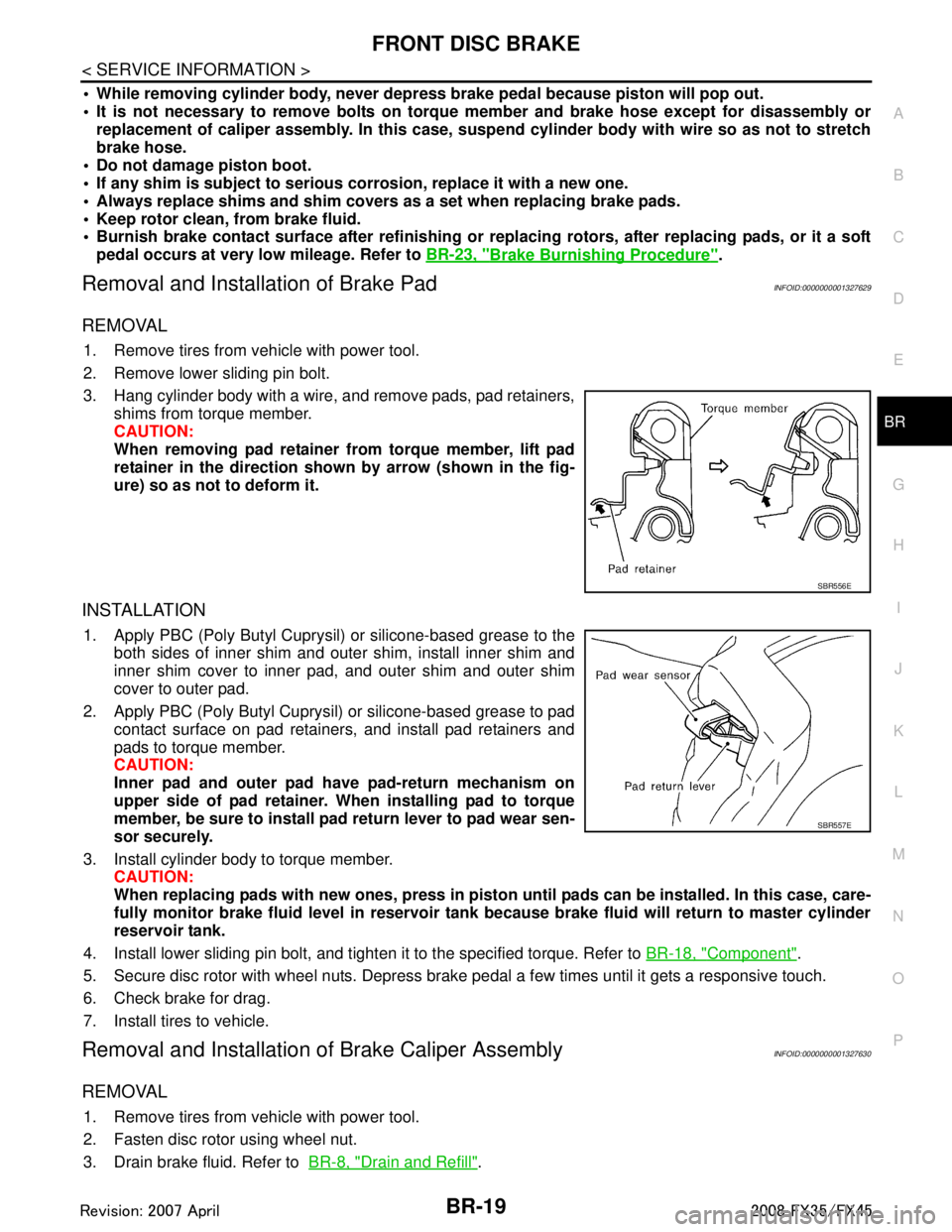
3. Hang cylinder body with a wire, and remove pads, pad retainers,
shims from torque member.
CAUTION:
When removing pad retainer from torque member, lift pad
retainer in the direction show n by arrow (shown in the fig-
ure) so as not to deform it.
INSTALLATION
1. Apply PBC (Poly Butyl Cuprysil) or silicone-based grease to the both sides of inner shim and outer shim, install inner shim and
inner shim cover to inner pad, and outer shim and outer shim
cover to outer pad.
2. Apply PBC (Poly Butyl Cuprysil) or silicone-based grease to pad contact surface on pad retainers, and install pad retainers and
pads to torque member.
CAUTION:
Inner pad and outer pad have pad-return mechanism on
upper side of pad retainer. When installing pad to torque
member, be sure to install pad return lever to pad wear sen-
sor securely.
3. Install cylinder body to torque member. CAUTION:
When replacing pads with new ones, press in piston until pads can be installed. In this case, care-
fully monitor brake fluid level in reservoir tank because brake fluid will return to master cylinder
reservoir tank.
4. Install lower sliding pin bolt, and tighten it to the specified torque. Refer to BR-18, "
Component".
5. Secure disc rotor with wheel nuts. Depress brake pedal a few times until it gets a responsive touch.
6. Check brake for drag.
7. Install tires to vehicle.
Removal and Installation of Brake Caliper AssemblyINFOID:0000000001327630
REMOVAL
1. Remove tires from vehicle with power tool.
2. Fasten disc rotor using wheel nut.
3. Drain brake fluid. Refer to BR-8, "
Drain and Refill".
SBR556E
SBR557E
3AA93ABC3ACD3AC03ACA3AC03AC63AC53A913A773A893A873A873A8E3A773A983AC73AC93AC03AC3
3A893A873A873A8F3A773A9D3AAF3A8A3A8C3A863A9D3AAF3A8B3A8C
Page 1006 of 3924
BR-22
< SERVICE INFORMATION >
FRONT DISC BRAKE
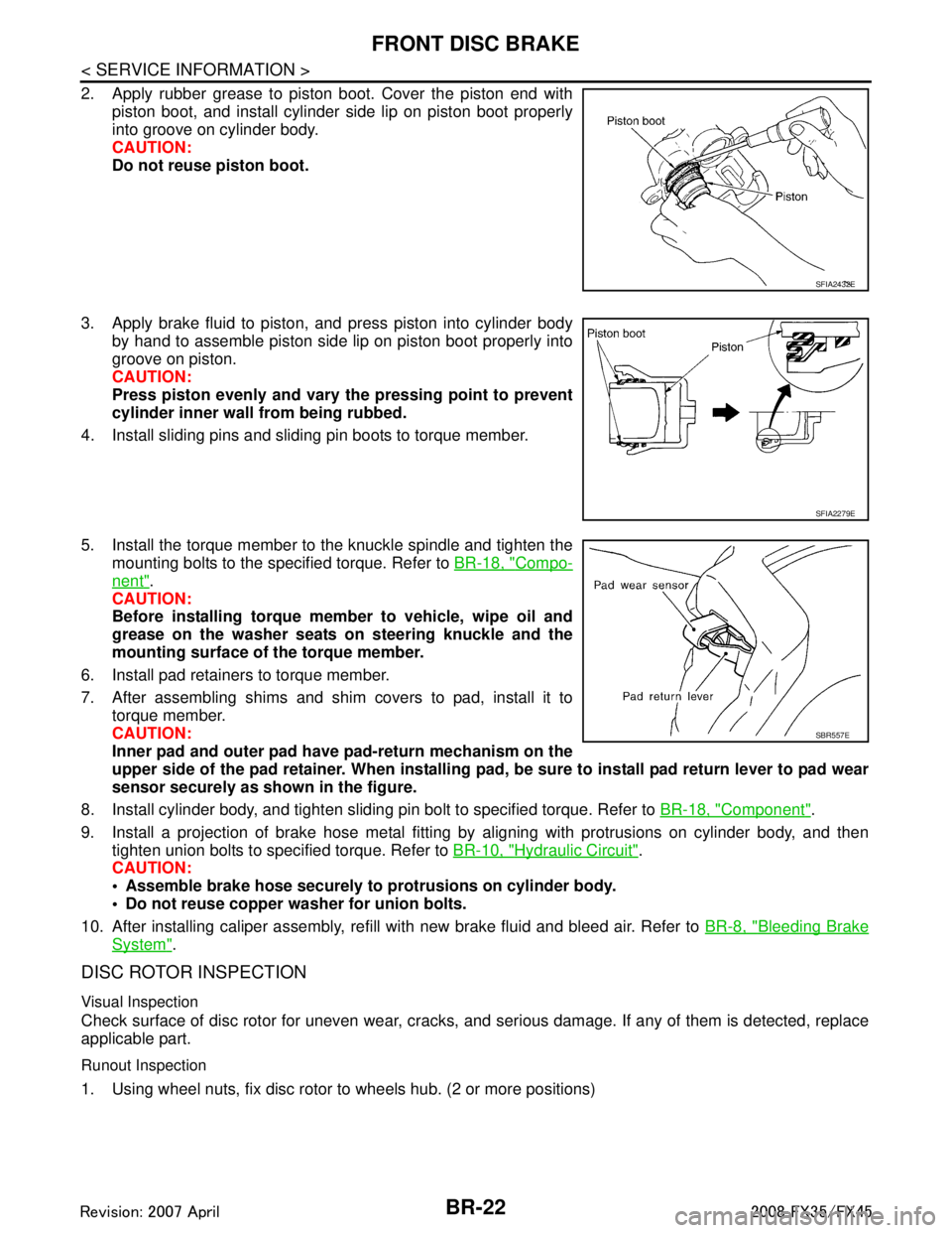
2. Apply rubber grease to piston boot. Cover the piston end withpiston boot, and install cylinder side lip on piston boot properly
into groove on cylinder body.
CAUTION:
Do not reuse piston boot.
3. Apply brake fluid to piston, and press piston into cylinder body by hand to assemble piston side lip on piston boot properly into
groove on piston.
CAUTION:
Press piston evenly and vary the pressing point to prevent
cylinder inner wall from being rubbed.
4. Install sliding pins and sliding pin boots to torque member.
5. Install the torque member to the knuckle spindle and tighten the mounting bolts to the specified torque. Refer to BR-18, "
Compo-
nent".
CAUTION:
Before installing torque member to vehicle, wipe oil and
grease on the washer seats on steering knuckle and the
mounting surface of the torque member.
6. Install pad retainers to torque member.
7. After assembling shims and shim covers to pad, install it to torque member.
CAUTION:
Inner pad and outer pad have pad-return mechanism on the
upper side of the pad retainer. When installing pad, be sure to install pad return lever to pad wear
sensor securely as shown in the figure.
8. Install cylinder body, and tighten sliding pin bolt to specified torque. Refer to BR-18, "
Component".
9. Install a projection of brake hose metal fitting by aligning with protrusions on cylinder body, and then tighten union bolts to specified torque. Refer to BR-10, "
Hydraulic Circuit".
CAUTION:
Assemble brake hose securely to protrusions on cylinder body.
Do not reuse copper washer for union bolts.
10. After installing caliper assembly, refill with new brake fluid and bleed air. Refer to BR-8, "
Bleeding Brake
System".
DISC ROTOR INSPECTION
Visual Inspection
Check surface of disc rotor for uneven wear, cracks, and serious damage. If any of them is detected, replace
applicable part.
Runout Inspection
1. Using wheel nuts, fix disc rotor to wheels hub. (2 or more positions)
SFIA2432E
SFIA2279E
SBR557E
3AA93ABC3ACD3AC03ACA3AC03AC63AC53A913A773A893A873A873A8E3A773A983AC73AC93AC03AC3
3A893A873A873A8F3A773A9D3AAF3A8A3A8C3A863A9D3AAF3A8B3A8C
Page 1007 of 3924
FRONT DISC BRAKEBR-23
< SERVICE INFORMATION >
C
DE
G H
I
J
K L
M A
B
BR
N
O P
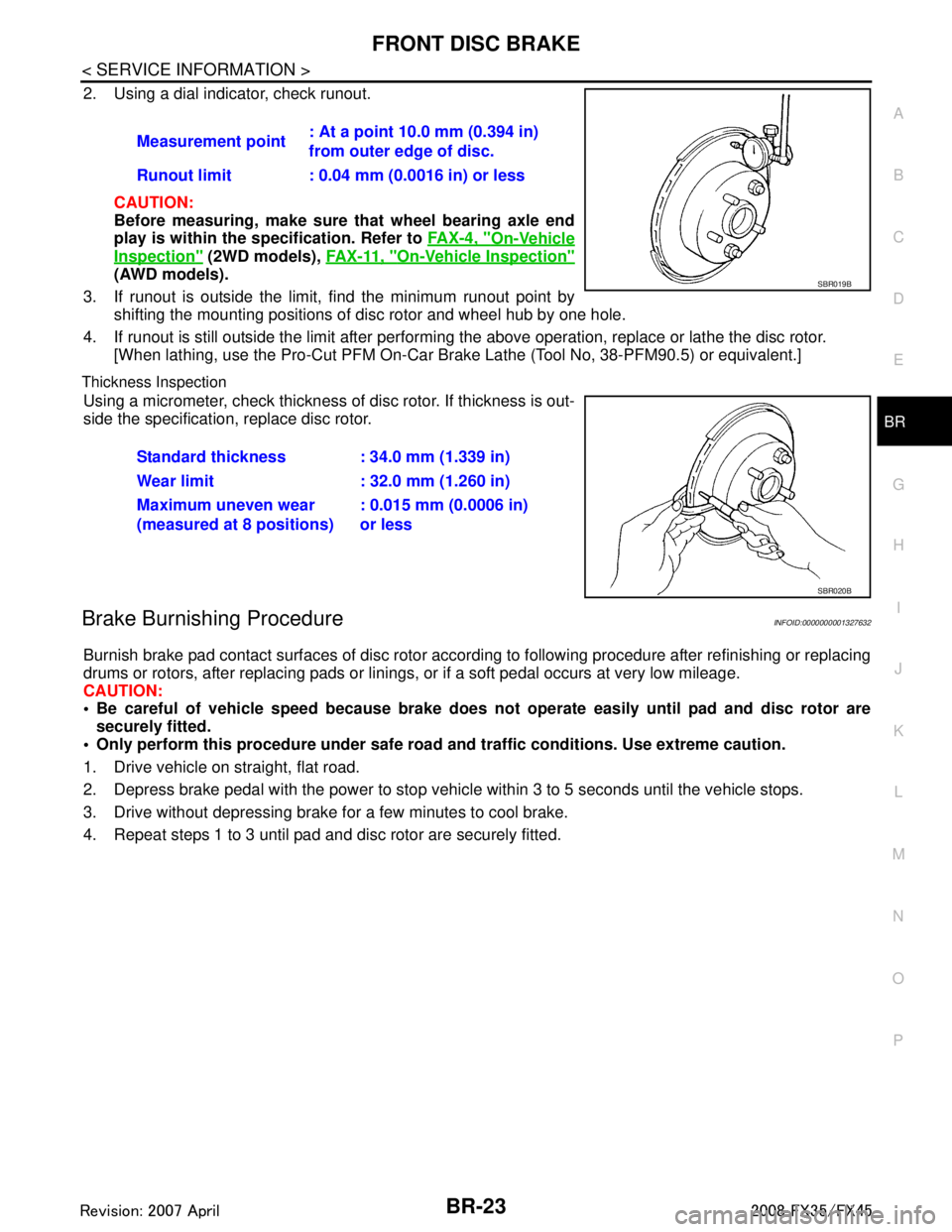
2. Using a dial indicator, check runout.
CAUTION:
Before measuring, make sure that wheel bearing axle end
play is within the sp ecification. Refer to FA X - 4 , "
On-Vehicle
Inspection" (2WD models), FA X - 11 , "On-Vehicle Inspection"
(AWD models).
3. If runout is outside the limit, find the minimum runout point by shifting the mounting positions of disc rotor and wheel hub by one hole.
4. If runout is still outside the limit after performing the above operation, replace or lathe the disc rotor.
[When lathing, use the Pro-Cut PFM On-Car Br ake Lathe (Tool No, 38-PFM90.5) or equivalent.]
Thickness Inspection
Using a micrometer, check thickness of disc rotor. If thickness is out-
side the specification, replace disc rotor.
Brake Burnishing ProcedureINFOID:0000000001327632
Burnish brake pad contact surfaces of disc rotor according to following procedure after refinishing or replacing
drums or rotors, after replacing pads or linings, or if a soft pedal occurs at very low mileage.
CAUTION:
Be careful of vehicle speed because brake does no t operate easily until pad and disc rotor are
securely fitted.
Only perform this procedure under safe road and traffic conditions. Use extreme caution.
1. Drive vehicle on straight, flat road.
2. Depress brake pedal with the power to stop vehicl e within 3 to 5 seconds until the vehicle stops.
3. Drive without depressing brake for a few minutes to cool brake.
4. Repeat steps 1 to 3 until pad and disc rotor are securely fitted. Measurement point
: At a point 10.0 mm (0.394 in)
from outer edge of disc.
Runout limit : 0.04 mm (0.0016 in) or less
SBR019B
Standard thickness : 34.0 mm (1.339 in)
Wear limit : 32.0 mm (1.260 in)
Maximum uneven wear
(measured at 8 positions) : 0.015 mm (0.0006 in)
or less
SBR020B
3AA93ABC3ACD3AC03ACA3AC03AC63AC53A913A773A893A873A873A8E3A773A983AC73AC93AC03AC3
3A893A873A873A8F3A773A9D3AAF3A8A3A8C3A863A9D3AAF3A8B3A8C
Page 1009 of 3924
REAR DISC BRAKEBR-25
< SERVICE INFORMATION >
C
DE
G H
I
J
K L
M A
B
BR
N
O P
WARNING:
Clean dust on caliper and brake pad with a vacuum du st collector to minimize the hazard of airborne
particles or other materials.
CAUTION:
While removing cylinder body, never depr ess brake pedal because piston will pop out.
It is not necessary to remove bolts on torq ue member and brake hose except for disassembly or
replacement of caliper assembly. In this case, hang cylinder body with a wire so as not to stretch
brake hose.
Do not damage piston boot.
If any shim is subject to serious corrosion, replace it with a new one.
Always replace shims and shim covers as a set when replacing brake pads.
Keep rotor clean, from brake fluid.
Burnish brake contact surface after refinishing or replacing rotors, after replacing pads, or if a soft
pedal occurs at very low mileage. Refer to BR-29, "
Brake Burnishing Procedure".
Removal and Installation of Brake PadINFOID:0000000001327635
REMOVAL
1. Remove tires from vehicle with power tool.
2. Remove sliding pin bolt (one on top).
3. Suspend cylinder body with a wire, and remove pads, pad retainers, shim from torque member.
INSTALLATION
1. Apply PBC (Poly Butyl Cuprysil) grease or silic one-based grease to the backside of pad and to both sides
of shim, and install inner shim and shim cover to inner pad, and install the outer shim to outer pad.
2. Install pad retainer and mount pad assemblies to torque member.
3. Push piston in so that pad is firmly installed and mount cylinder body to torque member. CAUTION:
When replacing pads with new ones, press in piston until pads can be installed. In this case, care-
fully monitor brake fluid level in reservoir tank because brake fluid will return to master cylinder
reservoir tank.
4. Install sliding pin bolt (one on top) and tighten to the specified torque. Refer to BR-24, "
Component".
5. Check brake for drag.
6. Install tires to the vehicle.
Removal and Installation of Brake Caliper AssemblyINFOID:0000000001327636
REMOVAL
1. Remove tires from vehicle with power tool.
2. Fasten disc rotor using wheel nut.
3. Drain brake fluid. Refer to BR-8, "
Drain and Refill".
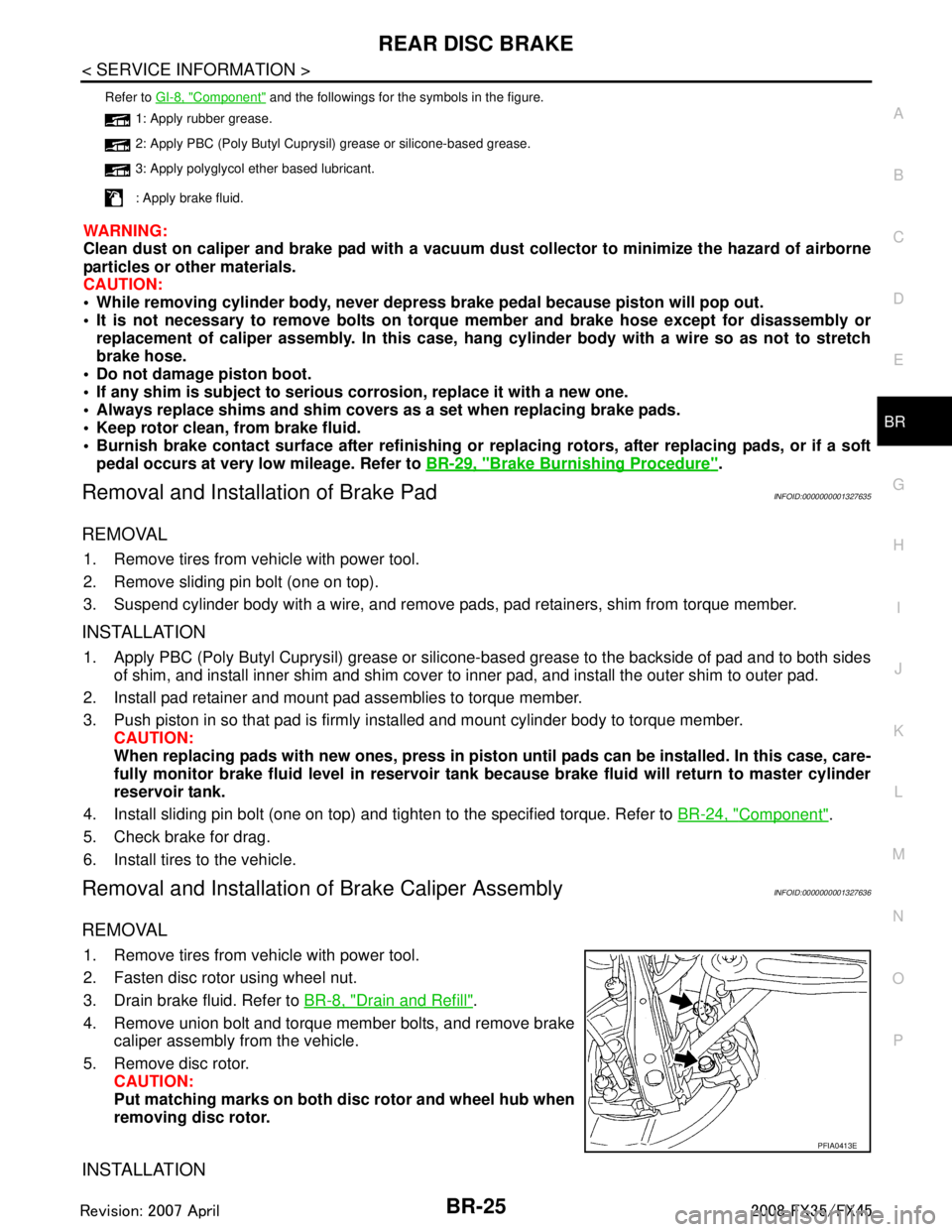
4. Remove union bolt and torque member bolts, and remove brake caliper assembly from the vehicle.
5. Remove disc rotor. CAUTION:
Put matching marks on both disc rotor and wheel hub when
removing disc rotor.
INSTALLATION
Refer to GI-8, "Component" and the followings for the symbols in the figure.
1: Apply rubber grease.
2: Apply PBC (Poly Butyl Cuprysil) grease or silicone-based grease.
3: Apply polyglycol ether based lubricant.
: Apply brake fluid.
PFIA0413E
3AA93ABC3ACD3AC03ACA3AC03AC63AC53A913A773A893A873A873A8E3A773A983AC73AC93AC03AC3
3A893A873A873A8F3A773A9D3AAF3A8A3A8C3A863A9D3AAF3A8B3A8C