2008 INFINITI FX35 Runout limit
[x] Cancel search: Runout limitPage 1007 of 3924
FRONT DISC BRAKEBR-23
< SERVICE INFORMATION >
C
DE
G H
I
J
K L
M A
B
BR
N
O P
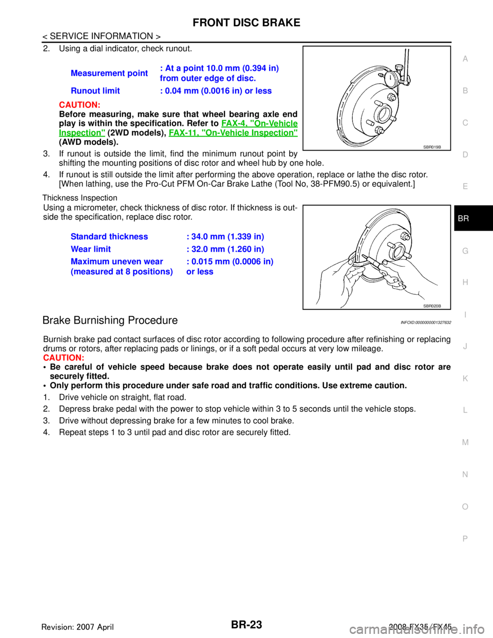
2. Using a dial indicator, check runout.
CAUTION:
Before measuring, make sure that wheel bearing axle end
play is within the sp ecification. Refer to FA X - 4 , "
On-Vehicle
Inspection" (2WD models), FA X - 11 , "On-Vehicle Inspection"
(AWD models).
3. If runout is outside the limit, find the minimum runout point by shifting the mounting positions of disc rotor and wheel hub by one hole.
4. If runout is still outside the limit after performing the above operation, replace or lathe the disc rotor.
[When lathing, use the Pro-Cut PFM On-Car Br ake Lathe (Tool No, 38-PFM90.5) or equivalent.]
Thickness Inspection
Using a micrometer, check thickness of disc rotor. If thickness is out-
side the specification, replace disc rotor.
Brake Burnishing ProcedureINFOID:0000000001327632
Burnish brake pad contact surfaces of disc rotor according to following procedure after refinishing or replacing
drums or rotors, after replacing pads or linings, or if a soft pedal occurs at very low mileage.
CAUTION:
Be careful of vehicle speed because brake does no t operate easily until pad and disc rotor are
securely fitted.
Only perform this procedure under safe road and traffic conditions. Use extreme caution.
1. Drive vehicle on straight, flat road.
2. Depress brake pedal with the power to stop vehicl e within 3 to 5 seconds until the vehicle stops.
3. Drive without depressing brake for a few minutes to cool brake.
4. Repeat steps 1 to 3 until pad and disc rotor are securely fitted. Measurement point
: At a point 10.0 mm (0.394 in)
from outer edge of disc.
Runout limit : 0.04 mm (0.0016 in) or less
SBR019B
Standard thickness : 34.0 mm (1.339 in)
Wear limit : 32.0 mm (1.260 in)
Maximum uneven wear
(measured at 8 positions) : 0.015 mm (0.0006 in)
or less
SBR020B
3AA93ABC3ACD3AC03ACA3AC03AC63AC53A913A773A893A873A873A8E3A773A983AC73AC93AC03AC3
3A893A873A873A8F3A773A9D3AAF3A8A3A8C3A863A9D3AAF3A8B3A8C
Page 1012 of 3924
BR-28
< SERVICE INFORMATION >
REAR DISC BRAKE
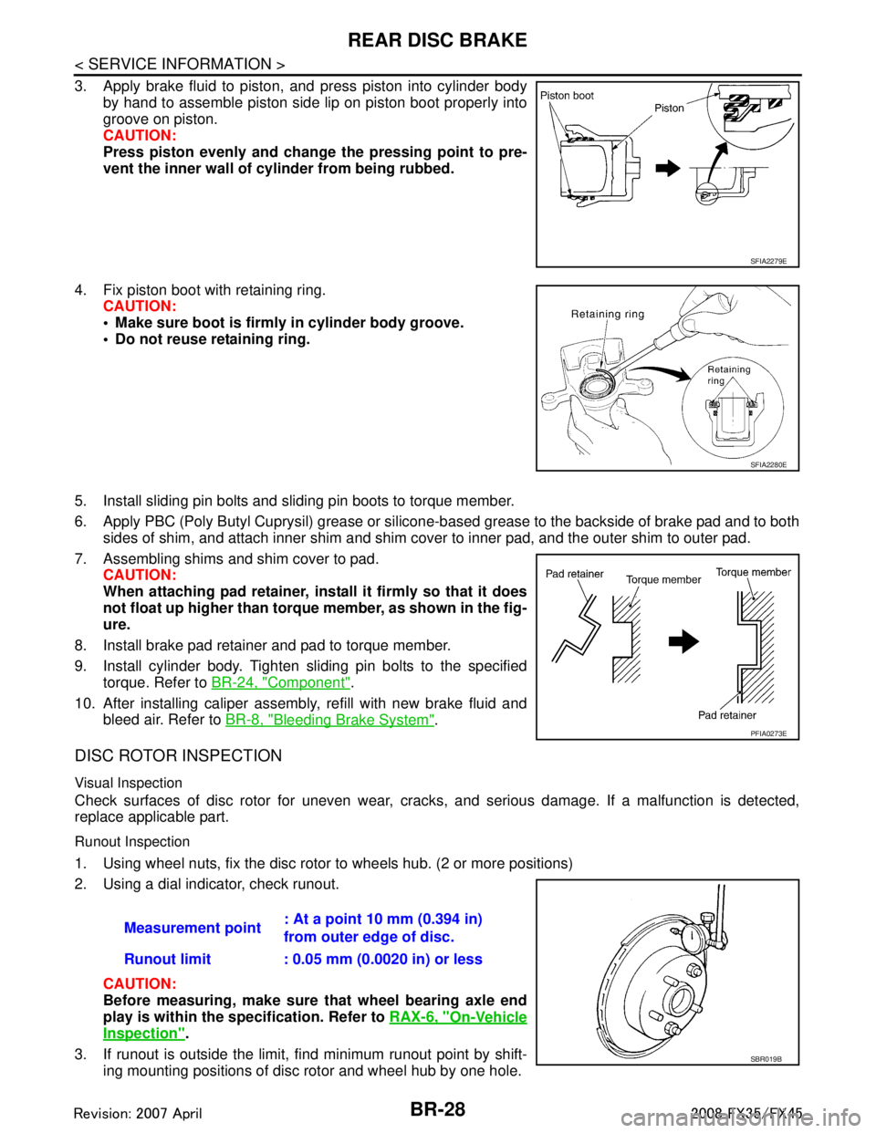
3. Apply brake fluid to piston, and press piston into cylinder bodyby hand to assemble piston side lip on piston boot properly into
groove on piston.
CAUTION:
Press piston evenly and change the pressing point to pre-
vent the inner wall of cylinder from being rubbed.
4. Fix piston boot with retaining ring. CAUTION:
Make sure boot is firmly in cylinder body groove.
Do not reuse retaining ring.
5. Install sliding pin bolts and sliding pin boots to torque member.
6. Apply PBC (Poly Butyl Cuprysil) grease or silicone- based grease to the backside of brake pad and to both
sides of shim, and attach inner shim and shim cover to inner pad, and the outer shim to outer pad.
7. Assembling shims and shim cover to pad. CAUTION:
When attaching pad retainer, inst all it firmly so that it does
not float up higher than torque member, as shown in the fig-
ure.
8. Install brake pad retainer and pad to torque member.
9. Install cylinder body. Tighten sliding pin bolts to the specified torque. Refer to BR-24, "
Component".
10. After installing caliper assembly, refill with new brake fluid and bleed air. Refer to BR-8, "
Bleeding Brake System".
DISC ROTOR INSPECTION
Visual Inspection
Check surfaces of disc rotor for uneven wear, cra cks, and serious damage. If a malfunction is detected,
replace applicable part.
Runout Inspection
1. Using wheel nuts, fix the disc rotor to wheels hub. (2 or more positions)
2. Using a dial indicator, check runout.
CAUTION:
Before measuring, make sure that wheel bearing axle end
play is within the specification. Refer to RAX-6, "
On-Vehicle
Inspection".
3. If runout is outside the limit, find minimum runout point by shift- ing mounting positions of disc rotor and wheel hub by one hole.
SFIA2279E
SFIA2280E
PFIA0273E
Measurement point : At a point 10 mm (0.394 in)
from outer edge of disc.
Runout limit : 0.05 mm (0.0020 in) or less
SBR019B
3AA93ABC3ACD3AC03ACA3AC03AC63AC53A913A773A893A873A873A8E3A773A983AC73AC93AC03AC3
3A893A873A873A8F3A773A9D3AAF3A8A3A8C3A863A9D3AAF3A8B3A8C
Page 1013 of 3924
REAR DISC BRAKEBR-29
< SERVICE INFORMATION >
C
DE
G H
I
J
K L
M A
B
BR
N
O P
4. If runout is still outside the limit after performing the above operation, replace or lathe the disc rotor.
[When lathing, use the Pro-Cut PFM On-Car Br ake Lathe (Tool No, 38-PFM90.5) or equivalent.]
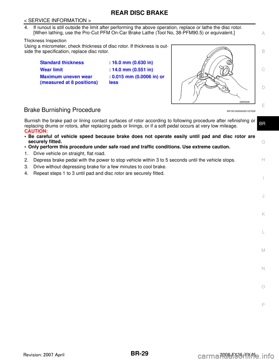
Thickness Inspection
Using a micrometer, check thickness of disc rotor. If thickness is out-
side the specification, replace disc rotor.
Brake Burnishing ProcedureINFOID:0000000001327638
Burnish the brake pad or lining contact surfaces of rotor according to following procedure after refinishing or
replacing drums or rotors, after replacing pads or li nings, or if a soft pedal occurs at very low mileage.
CAUTION:
Be careful of vehicle speed because brake does no t operate easily until pad and disc rotor are
securely fitted.
Only perform this procedure under safe road and traffic conditions. Use extreme caution.
1. Drive vehicle on straight, flat road.
2. Depress brake pedal with the power to stop vehicl e within 3 to 5 seconds until the vehicle stops.
3. Drive without depressing brake for a few minutes to cool brake.
4. Repeat steps 1 to 3 until pad and disc rotor are securely fitted. Standard thickness : 16.0 mm (0.630 in)
Wear limit : 14.0 mm (0.551 in)
Maximum uneven wear
(measured at 8 positions)
: 0.015 mm (0.0006 in) or
less
SBR020B
3AA93ABC3ACD3AC03ACA3AC03AC63AC53A913A773A893A873A873A8E3A773A983AC73AC93AC03AC3
3A893A873A873A8F3A773A9D3AAF3A8A3A8C3A863A9D3AAF3A8B3A8C
Page 1014 of 3924

BR-30
< SERVICE INFORMATION >
SERVICE DATA AND SPECIFICATIONS (SDS)
SERVICE DATA AND SPECIFICATIONS (SDS)
General SpecificationINFOID:0000000001327639
Unit: mm (in)
Brake PedalINFOID:0000000001327640
Brake BoosterINFOID:0000000001327641
Vacuum type
Check ValveINFOID:0000000001327642
Front Disc BrakeINFOID:0000000001327643
Rear Disc BrakeINFOID:0000000001327644
Front brakeRotor outer diameter
× thickness 320 × 34 (12.598 × 1.339)
Pad length × width × thickness 130.0 × 50.0 × 11.0 (5.118 × 1.969 × 0.433)
Cylinder bore diameter 45.0 (1.772) × 2
Rear brake Rotor outer diameter
× thickness 308 × 16 (12.13 × 0.63)
Pad length × width × thickness 83.0 × 33.0 × 8.5 (3.268 × 1.299 × 0.335)
Cylinder bore diameter 42.86 (1.6874)
Master cylinder Cylinder bore diameter 25.4 (1.00)
Control valve Valve model Electric brake force distribution
Brake booster Diaphragm diameter Primary 228.5 (9.0)
Secondary 203.0 (8.0)
Recommended brake fluid DOT 3
Brake pedal height (from dash lower panel top surface) 161.5 − 171.5 mm (6.358 − 6.752 in)
Depressed pedal height
[under a force of 490 N (50 kg, 110 lb) with engine running] More than 95 mm (3.74 in)
Clearance between stopper rubber and the threaded end of stop lamp
switch and ASCD cancel switch (or brake switch) 0.74
− 1.96 mm (0.0291 − 0.0772 in)
Pedal play 3 − 11 mm (0.12 − 0.43 in)
Output rod length 15.6 − 15.9 mm (0.614 − 0.626 in)
Input rod length 126.5 mm (4.98 in)
Vacuum leakage
[at a vacuum of –66.7 kPa (–500 mmHg, –19.69 inHg)]Within vacuum of 1.3 kPa (10 mmHg, 0.39 inHg) for 15
seconds
Brake padStandard thickness 11.0 mm (0.433 in)
Repair limit thickness 2.0 mm (0.079 in)
Disc rotor Standard thickness 34.0 mm (1.339 in)
Wear limit 32.0 mm (1.260 in)
Maximum uneven wear (measured at 8 positions) 0.015mm (0.0006 in) or less
Runout limit (with the disc rotor attached to the vehicle) 0.04 mm (0.0016 in) or less
Brake pad
Standard thickness 8.5 mm (0.335 in)
Repair limit thickness 2.0 mm (0.079 in)
3AA93ABC3ACD3AC03ACA3AC03AC63AC53A913A773A893A873A873A8E3A773A983AC73AC93AC03AC3
3A893A873A873A8F3A773A9D3AAF3A8A3A8C3A863A9D3AAF3A8B3A8C
Page 1015 of 3924

SERVICE DATA AND SPECIFICATIONS (SDS)
BR-31
< SERVICE INFORMATION >
C
D E
G H
I
J
K L
M A
B
BR
N
O P
Disc rotor Standard thickness 16.0 mm (0.630 in)
Wear limit 14.0 mm (0.551 in)
Maximum uneven wear (measured at 8 positions) 0.015 mm (0.0006 in) or less
Runout limit (with the disc rotor attached to the vehicle) 0.05 mm (0.0020 in) or less
3AA93ABC3ACD3AC03ACA3AC03AC63AC53A913A773A893A873A873A8E3A773A983AC73AC93AC03AC3
3A893A873A873A8F3A773A9D3AAF3A8A3A8C3A863A9D3AAF3A8B3A8C
Page 2569 of 3924
![INFINITI FX35 2008 Service Manual
CAMSHAFTEM-85
< SERVICE INFORMATION > [VQ35DE]
C
D
E
F
G H
I
J
K L
M A
EM
NP
O
6. Remove valve lifter.
Identify installation positions, and store them without mixing them up.
7. Remove timing chain](/manual-img/42/57017/w960_57017-2568.png "INFINITI FX35 2008 Service Manual
CAMSHAFTEM-85
< SERVICE INFORMATION > [VQ35DE]
C
D
E
F
G H
I
J
K L
M A
EM
NP
O
6. Remove valve lifter.
Identify installation positions, and store them without mixing them up.
7. Remove timing chain")
CAMSHAFTEM-85
< SERVICE INFORMATION > [VQ35DE]
C
D
E
F
G H
I
J
K L
M A
EM
NP
O
6. Remove valve lifter.
Identify installation positions, and store them without mixing them up.
7. Remove timing chain tensioner (secondary) from cylinder head. Remove timing chain tensioner (secondary) with its stopperpin attached.
NOTE:
Stopper pin was attached when timing chain (secondary) was
removed.
INSPECTION AFTER REMOVAL
Camshaft Runout
1. Put V-block on precise flat table, and support No. 2 and 4 jour- nals of camshaft.
CAUTION:
Do not support No. 1 journal (on the side of camshaft
sprocket) because it has a different diameter from the other
three locations.
2. Set a dial indicator vertically to No. 3 journal.
3. Turn camshaft to one direction with hands, and measure the camshaft runout on a dial indicator. (Total indicator reading)
4. If it exceeds the limit, replace camshaft.
Camshaft Cam Height
1. Measure the camshaft cam height with a micrometer.
2. If wear exceeds the limit, replace camshaft.
Camshaft Journa l Oil Clearance
CAMSHAFT JOURNAL DIAMETER
Measure the outer diameter of camshaft journal with a micrometer.
PBIC2111E
Standard : Less than 0.02 mm (0.0008 in)
Limit : 0.05 mm (0.0020 in)PBIC0929E
Standard cam height (intake and exhaust)
: 44.865 - 45.055 mm (1.7663 - 1.7738 in)
Cam wear limit : 0.2 mm (0.008 in)
EMQ0072D
Standard:No. 1 : 25.935 - 25.955 mm (1.0211 - 1.0218 in)
No. 2, 3, 4 : 23.445 - 23.465 mm (0.9230 - 0.9238 in)
PBIC0040E
3AA93ABC3ACD3AC03ACA3AC03AC63AC53A913A773A893A873A873A8E3A773A983AC73AC93AC03AC3
3A893A873A873A8F3A773A9D3AAF3A8A3A8C3A863A9D3AAF3A8B3A8C
Page 2570 of 3924
![INFINITI FX35 2008 Service Manual
EM-86
< SERVICE INFORMATION >[VQ35DE]
CAMSHAFT
CAMSHAFT BRACKET INNER DIAMETER
Tighten camshaft bracket bolt with the specified tor que. Refer to "INSTALLATION" for the tightening proce-
dure.
M](/manual-img/42/57017/w960_57017-2569.png "INFINITI FX35 2008 Service Manual
EM-86
< SERVICE INFORMATION >[VQ35DE]
CAMSHAFT
CAMSHAFT BRACKET INNER DIAMETER
Tighten camshaft bracket bolt with the specified tor que. Refer to \"INSTALLATION\" for the tightening proce-
dure.
M")
EM-86
< SERVICE INFORMATION >[VQ35DE]
CAMSHAFT
CAMSHAFT BRACKET INNER DIAMETER
Tighten camshaft bracket bolt with the specified tor que. Refer to "INSTALLATION" for the tightening proce-
dure.
Measure inner diameter “A” of camshaft bracket with a bore gauge.
CAMSHAFT JOURNA L OIL CLEARANCE (Oil clearance) = (Camshaft bracket inner diameter) – (Camshaft journal diameter).
If the calculated value exceeds the limit, replace either or both camshaft and cylinder head.
NOTE:
Camshaft brackets cannot be replaced as single part s, because there are machined together with cylinder
head. Replace whole cylinder head assembly.
Camshaft End Play
Install a dial indicator in thrust direction on front end of camshaft. Measure the end play of a dial indicator when camshaft is moved
forward/backward (in direction to axis).
Measure the following parts if out of the limit.
- Dimension “A” for camshaft No. 1 journal
- Dimension “B” for cylinder head No. 1 journal bearing
Refer to the standards above, and then replace camshaft and/or cylinder head.
Camshaft Sprocket Runout
1. Put V-block on precise flat table, and support No. 2 and 4 journals of camshaft. CAUTION:
Do not support No. 1 journal (on the side of cam shaft sprocket) because it has a different diameter
from the other three locations. Standard:
No. 1 : 26.000 - 26.021 mm (1.0236 - 1.0244 in)
No. 2, 3, 4 : 23.500 - 23.521 mm (0.9252 - 0.9260 in)
PBIC1645E
Standard:No. 1 : 0.045 - 0.086 mm (0.0018 - 0.0034 in)
No. 2, 3, 4 : 0.035 - 0.076 mm (0.0014 - 0.0030 in)
Limit : 0.15 mm (0.0059 in)
Standard : 0.115 - 0.188 mm (0.0045 - 0.0074 in)
Limit : 0.24 mm (0.0094 in)
SEM864E
Standard : 27.500 - 27.548 mm (1.0827 - 1.0846 in)
Standard : 27.360 - 27.385 mm (1.0772 - 1.0781 in)
KBIA2404J
3AA93ABC3ACD3AC03ACA3AC03AC63AC53A913A773A893A873A873A8E3A773A983AC73AC93AC03AC3
3A893A873A873A8F3A773A9D3AAF3A8A3A8C3A863A9D3AAF3A8B3A8C
Page 2571 of 3924
![INFINITI FX35 2008 Service Manual
CAMSHAFTEM-87
< SERVICE INFORMATION > [VQ35DE]
C
D
E
F
G H
I
J
K L
M A
EM
NP
O
2. Measure the camshaft sprocket runout with a dial indicator.
(Total indicator reading)
If it exceeds the limit, repl](/manual-img/42/57017/w960_57017-2570.png "INFINITI FX35 2008 Service Manual
CAMSHAFTEM-87
< SERVICE INFORMATION > [VQ35DE]
C
D
E
F
G H
I
J
K L
M A
EM
NP
O
2. Measure the camshaft sprocket runout with a dial indicator.
(Total indicator reading)
If it exceeds the limit, repl")
CAMSHAFTEM-87
< SERVICE INFORMATION > [VQ35DE]
C
D
E
F
G H
I
J
K L
M A
EM
NP
O
2. Measure the camshaft sprocket runout with a dial indicator.
(Total indicator reading)
If it exceeds the limit, replace camshaft sprocket.
Valve Lifter
Check if surface of valve lifter has any wear or cracks.
If anything above is found, replace valve lifter. Refer to EM-149,
"Standard and Limit".
Valve Lifter Clearance
VALVE LIFTER OUTER DIAMETER Measure the outer diameter at 1/2 height of valve lifter with a
micrometer since valve lifter is in barrel shape.
VALVE LIFTER HOLE DIAMETER Measure the inner diameter of va lve lifter hole of cylinder head with
an inside micrometer.
VALVE LIFTER CLEARANCE (Valve lifter clearance) = (Valve lifter hole diameter) – (Valve lifter outer diameter) Limit : 0.15 mm (0.0059 in)
PBIC0930E
KBIA0182E
Standard
Identification (stamped) mark “R” or “U” : 33.977 - 33.987 mm (1.3377 - 1.3381 in)
Identification (stamped) mark “V” : 33.980 - 33.990 mm (1.3378 - 1.3382 in)
JEM798G
Standard (Intake and exhaust): 34.000 - 34.016 mm (1.3386 - 1.3392 in)
SEM867E
StandardIdentification (stamped) mark “R” or “U” : 0.013 - 0.039 mm (0.0005 - 0.0015 in)
3AA93ABC3ACD3AC03ACA3AC03AC63AC53A913A773A893A873A873A8E3A773A983AC73AC93AC03AC3
3A893A873A873A8F3A773A9D3AAF3A8A3A8C3A863A9D3AAF3A8B3A8C