2008 INFINITI FX35 tire pressure
[x] Cancel search: tire pressurePage 3807 of 3924

TROUBLE DIAGNOSISTF-21
< SERVICE INFORMATION >
CEF
G H
I
J
K L
M A
B
TF
N
O P
*: The values are changed by throttle opening and engine speed.
CONSULT-III Function (ALL MODE AWD/4WD)INFOID:0000000001327442
FUNCTION
CONSULT-III can display each diagnostic item using the diagnostic test modes shown following.
FR LH SENSOR [km/h] or [mph] Wheel speed (Front wheel
left)Vehicle stopped 0.00 km/h (0.00 mph)
Vehicle running
CAUTION:
Check air pressure of tire under
standard condition.
Approximately equal to
the indication on speed-
ometer (Inside of
±10%)
RR RH SENSOR [km/h] or [mph] Wheel speed (Rear wheel
right)Vehicle stopped 0.00 km/h (0.00 mph)
Vehicle running
CAUTION:
Check air pressure of tire under
standard condition.
Approximately equal to
the indication on speed-
ometer (Inside of
±10%)
RR LH SENSOR [km/h] or [mph] Wheel speed (Rear wheel left) Vehicle stopped 0.00 km/h (0.00 mph)
Vehicle running
CAUTION:
Check air pressure of tire under
standard condition.Approximately equal to
the indication on speed-
ometer (Inside of
±10%)
BATTERY VOLT [V] Power supply voltage for AWD
control unitIgnition switch: ON Battery voltage
THRTL POS SEN [%] Throttle opening condition When depressing accelerator pedal
(Value rises gradually in response to
throttle position.)0 - 100%
ETS SOLENOID [A] Monitored value of current at
AWD solenoidEngine running
At idle speed
Approx. 0.000A
Engine running
When depressing accelerator ped- al Approx. 0.000 - 2.400A*
STOP LAMP SW [ON/OFF] Condition of brake pedal oper-
ationBrake pedal: Depressed ON
Brake pedal: Released OFF
ENG SPEED SIG [RUN/STOP] Condi tion of engine runningEngine stopped
(Engine speed: Less than 400 rpm)
STOP
Engine running
(Engine speed: 400 rpm or more) RUN
ETS ACTUATOR [ON/OFF] Operating condition of AWD
actuator relay (integrated in
AWD control unit)Engine stopped (Ignition
switch: ON)
OFF
Engine running ON
4WD WARN LAMP [ON/OFF] AWD warning lamp conditionAWD warning lamp: ON ON
AWD warning lamp: OFF OFF
4WD MODE MON [AUTO] Control status of AWD Engine running AUTO
DIS-TIRE MONI [mm] Improper size tire installed
conditionVehicle running with normal size tire
installed
0-4 mm
Vehicle running with improper size
tire installed (Front /rear tire size dif-
ference, wear condition) 4-8 mm, 8- mm
P BRAKE SW [ON/OFF] Condition of parking brake Parking brake operated ON
Parking brake not operated OFF
Monitored item [Unit] Content Condition Display value
3AA93ABC3ACD3AC03ACA3AC03AC63AC53A913A773A893A873A873A8E3A773A983AC73AC93AC03AC3
3A893A873A873A8F3A773A9D3AAF3A8A3A8C3A863A9D3AAF3A8B3A8C
Page 3820 of 3924
TF-34
< SERVICE INFORMATION >
TROUBLE DIAGNOSIS FOR SYMPTOMS
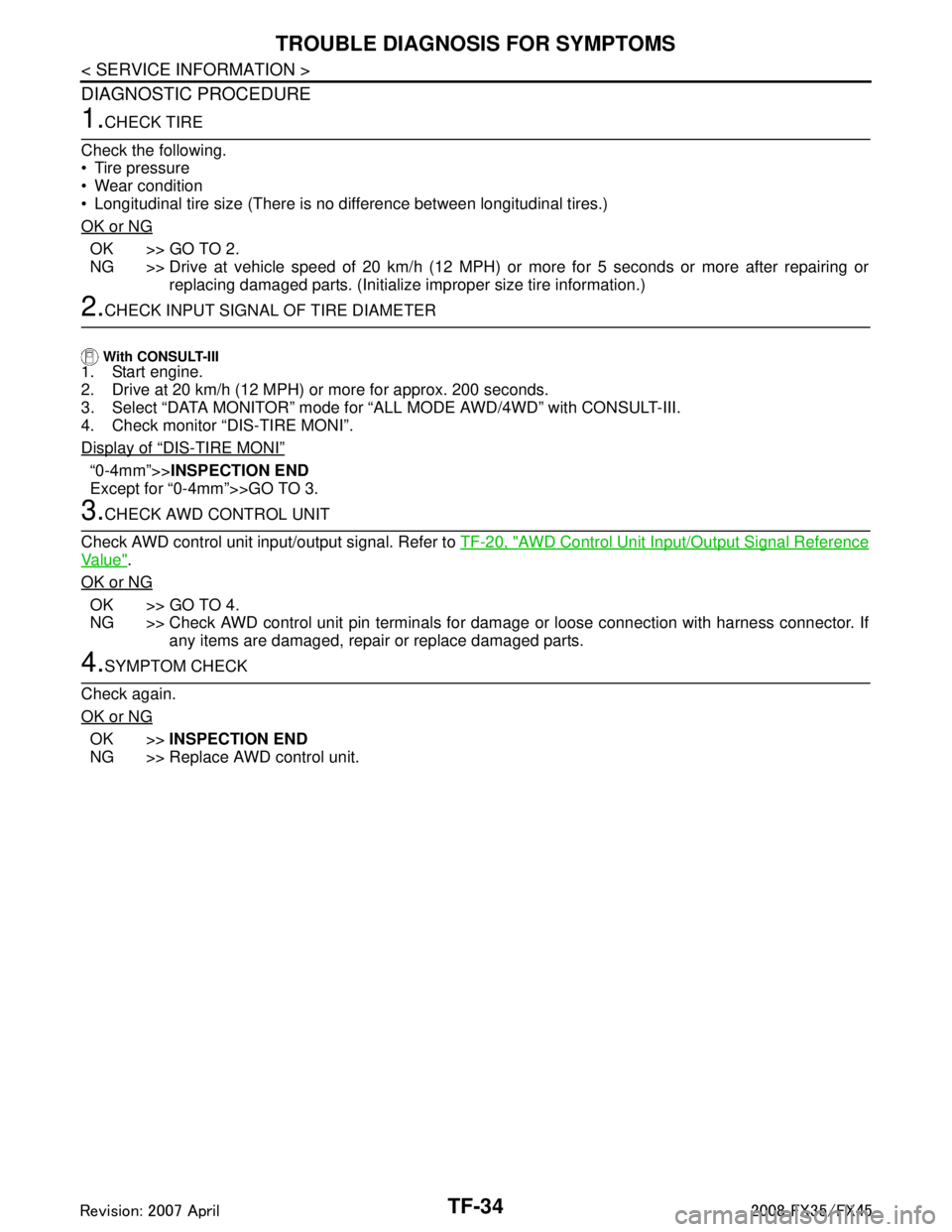
DIAGNOSTIC PROCEDURE
1.CHECK TIRE
Check the following.
Tire pressure
Wear condition
Longitudinal tire size (There is no difference between longitudinal tires.)
OK or NG
OK >> GO TO 2.
NG >> Drive at vehicle speed of 20 km/h (12 MPH) or more for 5 seconds or more after repairing or replacing damaged parts. (Initialize improper size tire information.)
2.CHECK INPUT SIGNAL OF TIRE DIAMETER
With CONSULT-III
1. Start engine.
2. Drive at 20 km/h (12 MPH) or more for approx. 200 seconds.
3. Select “DATA MONITOR” mode for “ALL MODE AWD/4WD” with CONSULT-III.
4. Check monitor “DIS-TIRE MONI”.
Display of
“DIS-TIRE MONI”
“0-4mm”>> INSPECTION END
Except for “0-4mm”>>GO TO 3.
3.CHECK AWD CONTROL UNIT
Check AWD control unit input/output signal. Refer to TF-20, "
AWD Control Unit Input/Output Signal Reference
Va l u e".
OK or NG
OK >> GO TO 4.
NG >> Check AWD control unit pin terminals for dam age or loose connection with harness connector. If
any items are damaged, repair or replace damaged parts.
4.SYMPTOM CHECK
Check again.
OK or NG
OK >> INSPECTION END
NG >> Replace AWD control unit.
3AA93ABC3ACD3AC03ACA3AC03AC63AC53A913A773A893A873A873A8E3A773A983AC73AC93AC03AC3
3A893A873A873A8F3A773A9D3AAF3A8A3A8C3A863A9D3AAF3A8B3A8C
Page 3841 of 3924

WT-1
SUSPENSION
C
DF
G H
I
J
K L
M
SECTION WT
A
B
WT
N
O PCONTENTS
ROAD WHEELS & TIRES
SERVICE INFORMATION .. ..........................2
INDEX FOR DTC ............................................ .....2
DTC No. Index .................................................... ......2
PRECAUTIONS ...................................................3
Precaution for Supplemental Restraint System
(SRS) "AIR BAG" and "SEAT BELT PRE-TEN-
SIONER" ............................................................. ......
3
Precaution .................................................................3
Service Notice or Precaution .....................................4
PREPARATION ...................................................5
Special Service Tool ........................................... ......5
Commercial Service Tool ..........................................5
NOISE, VIBRATION AND HARSHNESS
(NVH) TROUBLESHOOTING .............................
6
NVH Troubleshooting Chart ................................ ......6
ROAD WHEEL ....................................................7
Inspection ............................................................ ......7
ROAD WHEEL TIRE ASSEMBLY ......................8
Balancing Wheels (Bonding Weight Type) .......... ......8
Tire Rotation ..............................................................9
TIRE PRESSURE MONITORING SYSTEM .......10
System Component ............................................. ....10
System Description .................................................10
CAN COMMUNICATION ....................................13
System Description ............................................. ....13
TROUBLE DIAGNOSES ....................................14
Schematic ........................................................... ....14
Wiring Diagram- T/WARN - .....................................15
Control Unit Input/Output Signal Standard ..............17
ID Registration Procedure ................................... ....19
Transmitter Wake Up Operation ..............................20
Self-Diagnosis .........................................................20
CONSULT-III Function (BCM) .................................22
How to Perform Trouble Diagnosis for Quick and
Accurate Repair .......................................................
24
Preliminary Check ...................................................25
Malfunction Code/Symptom Chart ...........................26
TROUBLE DIAGNOSIS FOR SELF-DIAG-
NOSTIC ITEMS .................................................
28
Transmitter or Control Unit (BCM) ...........................28
Transmitter - 1 .........................................................28
Transmitter - 2 .........................................................29
Vehicle Speed Signal ..............................................29
TROUBLE DIAGNOSIS FOR SYMPTOMS ......30
Low Tire Pressure Warning Lamp Does Not Come
On When Ignition Switch Is Turned On ...................
30
Low Tire Pressure Warning Lamp Stays On When
Ignition Switch Is Turned On ............................... ....
30
Low Tire Pressure Warning Lamp Blinks When Ig-
nition Switch Is Turned On ......................................
31
Run-Flat Tire Warning Lamp Stays On When Igni-
tion Switch Is Turned On .........................................
32
Turn Signal Lamp Blinks When Ignition Switch Is
Turned On ...............................................................
32
ID Registration Cannot Be Completed ....................32
REMOVAL AND INSTALLATION .....................33
Transmitter ..............................................................33
SERVICE DATA AND SPECIFICATIONS
(SDS) .................................................................
35
Road Wheel .............................................................35
Tire ..........................................................................35
3AA93ABC3ACD3AC03ACA3AC03AC63AC53A913A773A893A873A873A8E3A773A983AC73AC93AC03AC3
3A893A873A873A8F3A773A9D3AAF3A8A3A8C3A863A9D3AAF3A8B3A8C
Page 3842 of 3924
WT-2
< SERVICE INFORMATION >
INDEX FOR DTC
SERVICE INFORMATION
INDEX FOR DTC
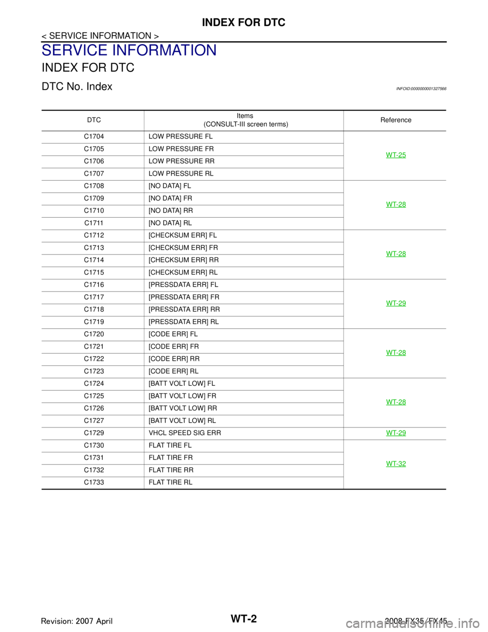
DTC No. IndexINFOID:0000000001327566
DTCItems
(CONSULT-III screen terms) Reference
C1704 LOW PRESSURE FL
WT-25
C1705 LOW PRESSURE FR
C1706 LOW PRESSURE RR
C1707 LOW PRESSURE RL
C1708 [NO DATA] FLWT-28
C1709 [NO DATA] FR
C1710 [NO DATA] RRC1711 [NO DATA] RL
C1712 [CHECKSUM ERR] FL
WT-28
C1713 [CHECKSUM ERR] FR
C1714 [CHECKSUM ERR] RR
C1715 [CHECKSUM ERR] RL
C1716 [PRESSDATA ERR] FLWT-29
C1717 [PRESSDATA ERR] FR
C1718 [PRESSDATA ERR] RR
C1719 [PRESSDATA ERR] RL
C1720 [CODE ERR] FLWT-28
C1721 [CODE ERR] FR
C1722 [CODE ERR] RR
C1723 [CODE ERR] RL
C1724 [BATT VOLT LOW] FLWT-28
C1725 [BATT VOLT LOW] FR
C1726 [BATT VOLT LOW] RR
C1727 [BATT VOLT LOW] RL
C1729 VHCL SPEED SIG ERRWT-29
C1730 FLAT TIRE FL
WT-32
C1731 FLAT TIRE FR
C1732 FLAT TIRE RR
C1733 FLAT TIRE RL
3AA93ABC3ACD3AC03ACA3AC03AC63AC53A913A773A893A873A873A8E3A773A983AC73AC93AC03AC3
3A893A873A873A8F3A773A9D3AAF3A8A3A8C3A863A9D3AAF3A8B3A8C
Page 3844 of 3924
WT-4
< SERVICE INFORMATION >
PRECAUTIONS
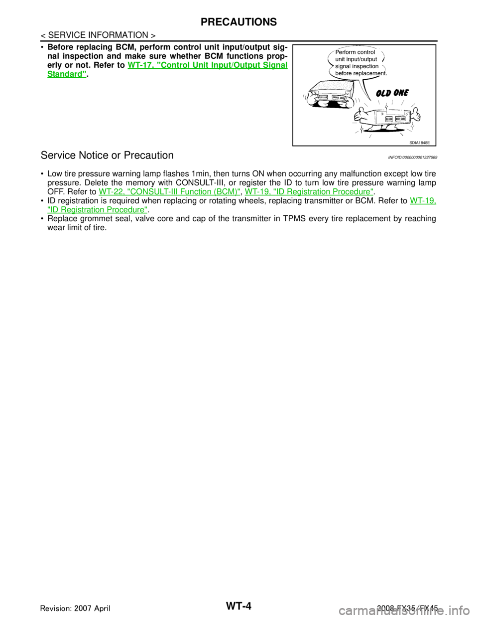
Before replacing BCM, perform c ontrol unit input/output sig-
nal inspection and make sure whether BCM functions prop-
erly or not. Refer to WT-17, "
Control Unit Input/Output Signal
Standard".
Service Notice or PrecautionINFOID:0000000001327569
Low tire pressure warning lamp flashes 1min, then turns ON when occurring any malfunction except low tire
pressure. Delete the memory with CONSULT-III, or regi ster the ID to turn low tire pressure warning lamp
OFF. Refer to WT-22, "
CONSULT-III Function (BCM)", WT-19, "ID Registration Procedure".
ID registration is required when replacing or rotati ng wheels, replacing transmitter or BCM. Refer to WT-19,
"ID Registration Procedure".
Replace grommet seal, valve core and cap of the transmi tter in TPMS every tire replacement by reaching
wear limit of tire.
SDIA1848E
3AA93ABC3ACD3AC03ACA3AC03AC63AC53A913A773A893A873A873A8E3A773A983AC73AC93AC03AC3
3A893A873A873A8F3A773A9D3AAF3A8A3A8C3A863A9D3AAF3A8B3A8C
Page 3846 of 3924

WT-6
< SERVICE INFORMATION >
NOISE, VIBRATION AND HARSHNESS (NVH) TROUBLESHOOTING
NOISE, VIBRATION AND HARSHNESS (NVH) TROUBLESHOOTING
NVH Troubleshooting ChartINFOID:0000000001327572
Use the chart below to help you find the cause of the sy mptom. If necessary, repair or replace these parts.
×: Applicable
Reference
FAX-4
,
FAX-11
, FSU-5
WT-7WT-8WT-35WT-9—
—
WT-35
NVH in PR section
NVH in RFD section
NVH in FAX and FSU section
NVH in RAX and RSU section Refer to TIRE in this chart.
Refer to ROAD WHEEL in this chart. NVH in FAX, RAX sectionNVH in BR section
NVH in PS section
Possible cause an d SUSPECTED PARTS
Improper installation, looseness
Out-of-round
Unbalance
Incorrect tire pressure
Uneven tire wear
Deformation or damage
Non-uniformity
Incorrect tire size
PROPELLER SHAFT
DIFFERENTIAL
FRONT AXLE AND FRONT SUSPENSION
REAR AXLE AND REAR SUSPENSION
TIRE
ROAD WHEEL
DRIVE SHAFT
BRAKE
STEERING
SymptomTIRE Noise
× ×××××× ×××× ××××
Shake ××××××××××××××
Vibration ×××××××
Shimmy × ××××××× ×× × ××
Judder ××××××× ×××××
Poor quality ride
or handling × ××××× × ×× ×
ROAD WHEEL Noise
× ×× × ××××× ×××
Shake × ×× × × ××× ×××
Shimmy, Judder ×××× ×××××
Poor quality ride
or handling ××× × ×××
3AA93ABC3ACD3AC03ACA3AC03AC63AC53A913A773A893A873A873A8E3A773A983AC73AC93AC03AC3
3A893A873A873A8F3A773A9D3AAF3A8A3A8C3A863A9D3AAF3A8B3A8C
Page 3850 of 3924
WT-10
< SERVICE INFORMATION >
TIRE PRESSURE MONITORING SYSTEM
TIRE PRESSURE MONITORING SYSTEM
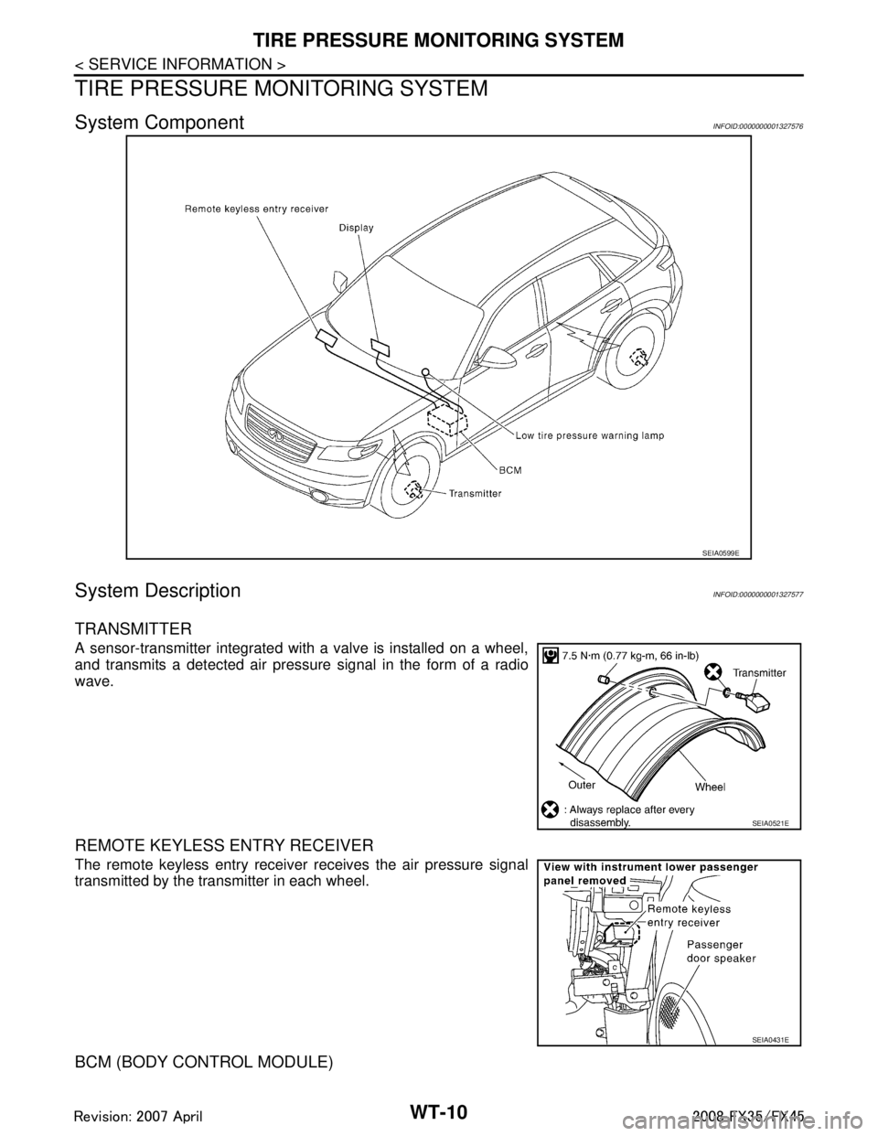
System ComponentINFOID:0000000001327576
System DescriptionINFOID:0000000001327577
TRANSMITTER
A sensor-transmitter integrated with a valve is installed on a wheel,
and transmits a detected air pressure signal in the form of a radio
wave.
REMOTE KEYLESS ENTRY RECEIVER
The remote keyless entry receiver receives the air pressure signal
transmitted by the transmitter in each wheel.
BCM (BODY CONTROL MODULE)
SEIA0599E
SEIA0521E
SEIA0431E
3AA93ABC3ACD3AC03ACA3AC03AC63AC53A913A773A893A873A873A8E3A773A983AC73AC93AC03AC3
3A893A873A873A8F3A773A9D3AAF3A8A3A8C3A863A9D3AAF3A8B3A8C
Page 3851 of 3924
TIRE PRESSURE MONITORING SYSTEMWT-11
< SERVICE INFORMATION >
C
DF
G H
I
J
K L
M A
B
WT
N
O P
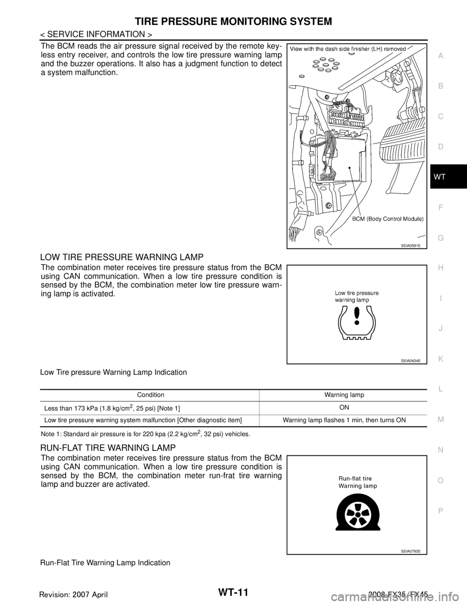
The BCM reads the air pressure signal received by the remote key-
less entry receiver, and controls the low tire pressure warning lamp
and the buzzer operations. It also has a judgment function to detect
a system malfunction.
LOW TIRE PRESSURE WARNING LAMP
The combination meter receives tire pressure status from the BCM
using CAN communication. When a low tire pressure condition is
sensed by the BCM, the combination meter low tire pressure warn-
ing lamp is activated.
Low Tire pressure Warning Lamp Indication
Note 1: Standard air pressure is for 220 kpa (2.2 kg/cm2, 32 psi) vehicles.
RUN-FLAT TIRE WARNING LAMP
The combination meter receives tire pressure status from the BCM
using CAN communication. When a low tire pressure condition is
sensed by the BCM, the combination meter run-frat tire warning
lamp and buzzer are activated.
Run-Flat Tire Warning Lamp Indication
SEIA0591E
SEIA0434E
Condition Warning lamp
Less than 173 kPa (1.8 kg/cm
2, 25 psi) [Note 1] ON
Low tire pressure warning system malfunction [Other diagnostic item] Warning lamp flashes 1 min, then turns ON
SEIA0792E
3AA93ABC3ACD3AC03ACA3AC03AC63AC53A913A773A893A873A873A8E3A773A983AC73AC93AC03AC3
3A893A873A873A8F3A773A9D3AAF3A8A3A8C3A863A9D3AAF3A8B3A8C