2008 INFINITI FX35 diagram
[x] Cancel search: diagramPage 3860 of 3924
WT-20
< SERVICE INFORMATION >
TROUBLE DIAGNOSES
4. Inflate all tires to proper pressure. Refer to WT-35, "Tire".
Transmitter Wake Up OperationINFOID:0000000001327583
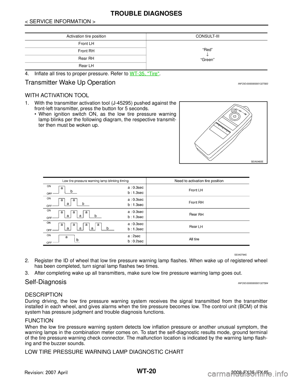
W I T H A C T I VAT I O N T O O L
1. With the transmitter activation tool (J-45295) pushed against the
front-left transmitter, press the button for 5 seconds.
When ignition switch ON, as the low tire pressure warninglamp blinks per the following diagram, the respective transmit-
ter then must be woken up.
2. Register the ID of wheel that low tire pressure warning lamp flashes. When wake up of registered wheel
has been completed, turn signal lamp flashes two times.
3. After completing wake up all transmitters, make sure low tire pressure warning lamp goes out.
Self-DiagnosisINFOID:0000000001327584
DESCRIPTION
During driving, the low tire pressure warning syste m receives the signal transmitted from the transmitter
installed in each wheel, and gives alarms when the tire pressure becomes low. The control unit (BCM) of this
system has pressure judgment and trouble diagnosis functions.
FUNCTION
When the low tire pressure warning system detects low inflation pressure or another unusual symptom, the
warning lamps in the combination meter comes on. To start the self-diagnostic results mode, ground terminal
of the tire pressure warning check connector. The malf unction location is indicated by the warning lamp flash-
ing and the buzzer sounds.
LOW TIRE PRESSURE WARNING LAMP DIAGNOSTIC CHART
Activation tire position CONSULT-III
Front LH “Red”↓
“Green”
Front RH
Rear RHRear LH
SEIA0460E
SEIA0794E
3AA93ABC3ACD3AC03ACA3AC03AC63AC53A913A773A893A873A873A8E3A773A983AC73AC93AC03AC3
3A893A873A873A8F3A773A9D3AAF3A8A3A8C3A863A9D3AAF3A8B3A8C
Page 3876 of 3924
WW-1
ELECTRICAL
C
DE
F
G H
I
J
L
M
SECTION WW
A
B
WW
N
O P
CONTENTS
WIPER, WASHER & HORN
SERVICE INFORMATION .. ..........................3
PRECAUTION ................................................ .....3
Precaution for Supplemental Restraint System
(SRS) "AIR BAG" and "SEAT BELT PRE-TEN-
SIONER" ............................................................. ......
3
Precaution for Procedure without Cowl Top Cover ......3
FRONT WIPER AND WASHER SYSTEM ..........4
Component Parts and Harness Connector Loca-
tion ...................................................................... ......
4
System Description ...................................................4
CAN Communication System Description .................6
CAN Communication Unit .........................................7
Schematic .................................................................7
Wiring Diagram - WIPER - ........................................8
Terminal and Reference Value for BCM .................10
Terminal and Reference Value for IPDM E/R .........14
How to Proceed with Trouble Diagnosis .................14
Preliminary Check ...................................................14
CONSULT-III Functions (BCM) ...............................15
CONSULT-III Functions (IPDM E/R) .......................16
Front Wiper Does Not Operate ...............................17
Front Wiper Does Not Return to Stop Position .......18
Only Front Wiper Low Does Not Operate ...............19
Only Front Wiper High Does Not Operate ...............20
Only Front Wiper Intermittent Does Not Operate ....21
Front Wiper Interval Time Is Not Controlled by Ve-
hicle Speed .............................................................
21
Front Wiper Intermittent Operation Switch Posi-
tion Cannot Be Adjusted .........................................
22
Wiper Does Not Wipe When Front Washer Oper-
ates .........................................................................
22
After Front Wiper Operate for 10 Seconds, They
Stop for 20 Seconds, and After Repeating the Op-
eration Five Times, They Become Inoperative ........
22
Front Wiper Does Not Stop .....................................23
Removal and Installation of Front Wiper Arms, Ad-
justment of Wiper Arms Stop Location ....................
23
Removal and Installation of Front Wiper Drive As-
sembly ................................................................. ....
24
Disassembly and Assembly of Front Wiper Drive
Assembly ............................................................. ....
25
Washer Nozzle Adjustment .....................................25
Washer Tube Layout ...............................................27
Removal and Installation of Front Washer Nozzle ....27
Removal and Installation of Front Washer Tube
Joint .........................................................................
27
Inspection of Washer Nozzle ...................................27
Inspection of Front Wiper and Washer Switch Cir-
cuit ...........................................................................
28
Removal and Installation of Front Wiper and
Washer Switch .........................................................
28
Removal and Installation of Washer Tank ...............28
Removal and Installation of Front and Rear Wash-
er Pump ...................................................................
29
REAR WIPER AND WASHER SYSTEM ..........30
Component Parts and Harness Connector Loca-
tion ...........................................................................
30
System Description ..................................................30
Wiring Diagram - WIP/ R - .......................................32
Terminal and Reference Value for BCM ..................33
How to Proceed with Trouble Diagnosis ..................35
Preliminary Check ...................................................36
CONSULT-III Functions (BCM) ...............................36
Rear Wiper Does Not Operate ................................37
Rear Wiper Does Not Return to Stop Position ........39
Only Rear Wiper ON Does Not Operate ..................40
Only Rear Wiper INT Does Not Operate .................40
Wiper Does Not Wipe When Rear Washer Oper-
ates ..........................................................................
40
Rear Wipers Do Not Stop ........................................40
Removal and Installation of Rear Wiper Arm, Ad-
justment of Wiper Arms Stop Location ....................
40
Removal and Installation of Rear Wiper Blade ........41
Removal and Installation of Rear Wiper Motor ........42
Washer Nozzle Adjustment .....................................43
Washer Tube Layout ...............................................43
Removal and Installation of Washer Nozzle ............43
Check Valve ............................................................44
3AA93ABC3ACD3AC03ACA3AC03AC63AC53A913A773A893A873A873A8E3A773A983AC73AC93AC03AC3
3A893A873A873A8F3A773A9D3AAF3A8A3A8C3A863A9D3AAF3A8B3A8C
Page 3877 of 3924

WW-2
Inspection of Front Wiper and Washer Switch Cir-
cuit ..........................................................................
44
Removal and Installation of Rear Wiper and
Washer Switch ........................................................
44
Removal and Installation of Washer Tank ..............44
Removal and Installation of Front and Rear Wash-
er pump ..................................................................
44
POWER SOCKET ..............................................45
Wiring Diagram - P/SCKT - ................................. ...45
Removal and Installation of Front Power Socket -
1 ........................................................................... ...
45
Removal and Installation of Front Power Socket -
2 ..............................................................................
46
Removal and Installation of Rear Power Socket .....46
Removal and Installation of Luggage Room Power
Socket .................................................................. ...
46
HORN .................................................................48
Wiring Diagram - HORN - .................................... ...48
Removal and Installation .........................................48
3AA93ABC3ACD3AC03ACA3AC03AC63AC53A913A773A893A873A873A8E3A773A983AC73AC93AC03AC3
3A893A873A873A8F3A773A9D3AAF3A8A3A8C3A863A9D3AAF3A8B3A8C
Page 3883 of 3924
WW-8
< SERVICE INFORMATION >
FRONT WIPER AND WASHER SYSTEM
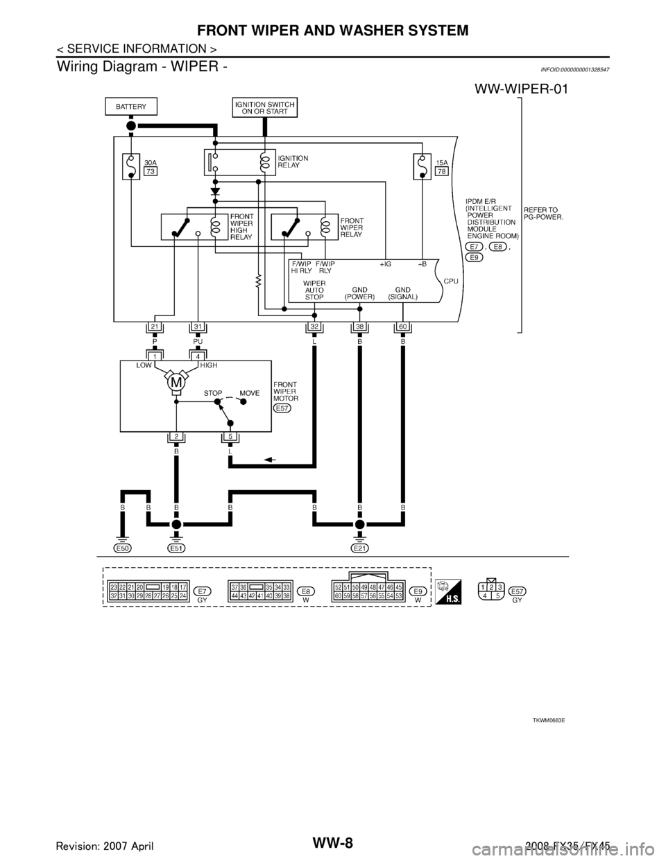
Wiring Diagram - WIPER -
INFOID:0000000001328547
TKWM0663E
3AA93ABC3ACD3AC03ACA3AC03AC63AC53A913A773A893A873A873A8E3A773A983AC73AC93AC03AC3
3A893A873A873A8F3A773A9D3AAF3A8A3A8C3A863A9D3AAF3A8B3A8C
Page 3889 of 3924
WW-14
< SERVICE INFORMATION >
FRONT WIPER AND WASHER SYSTEM
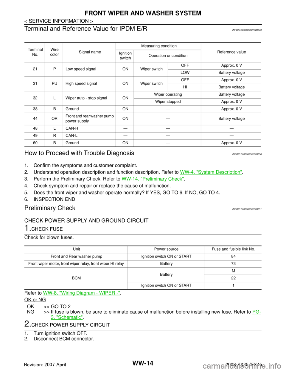
Terminal and Reference Value for IPDM E/R
INFOID:0000000001328549
How to Proceed with Trouble DiagnosisINFOID:0000000001328550
1. Confirm the symptoms and customer complaint.
2. Understand operation description and function description. Refer to WW-4, "
System Description".
3. Perform the Preliminary Check. Refer to WW-14, "
Preliminary Check".
4. Check symptom and repair or r eplace the cause of malfunction.
5. Does the front wiper and washer operate norma lly? If YES, GO TO 6. If NO, GO TO 4.
6. INSPECTION END
Preliminary CheckINFOID:0000000001328551
CHECK POWER SUPPLY AND GROUND CIRCUIT
1.CHECK FUSE
Check for blown fuses.
Refer to WW-8, "
Wiring Diagram - WIPER -".
OK or NG
OK >> GO TO 2
NG >> If fuse is blown, be sure to eliminate caus e of malfunction before installing new fuse, Refer to PG-
3, "Schematic".
2.CHECK POWER SUPPLY CIRCUIT
1. Turn ignition switch OFF.
2. Disconnect BCM connector.
Te r m i n a l No. Wire
color Signal name Measuring condition
Reference value
Ignition
switch Operation or condition
21 P Low speed signal ON Wiper switch OFF Approx. 0 V
LOW Battery voltage
31 PU High speed signal ON Wiper switch OFF Approx. 0 V
HI Battery voltage
32 L Wiper auto - stop signal ON Wiper operating Battery voltage
Wiper stopped Approx. 0 V
38 B Ground ON — Approx. 0 V
44 OR Front and rear washer pump
power supply ON — Battery voltage
48 L CAN-H — — —
49 R CAN-L — — —
60 B Ground ON — Approx. 0 V
Unit Power source Fuse and fusible link No.
Front and Rear washer pump Ignition switch ON or START 84
Front wiper motor, front wiper rela y, front wiper HI relay Battery 73
BCM BatteryM
22
Ignition switch ON or START 1
3AA93ABC3ACD3AC03ACA3AC03AC63AC53A913A773A893A873A873A8E3A773A983AC73AC93AC03AC3
3A893A873A873A8F3A773A9D3AAF3A8A3A8C3A863A9D3AAF3A8B3A8C
Page 3907 of 3924
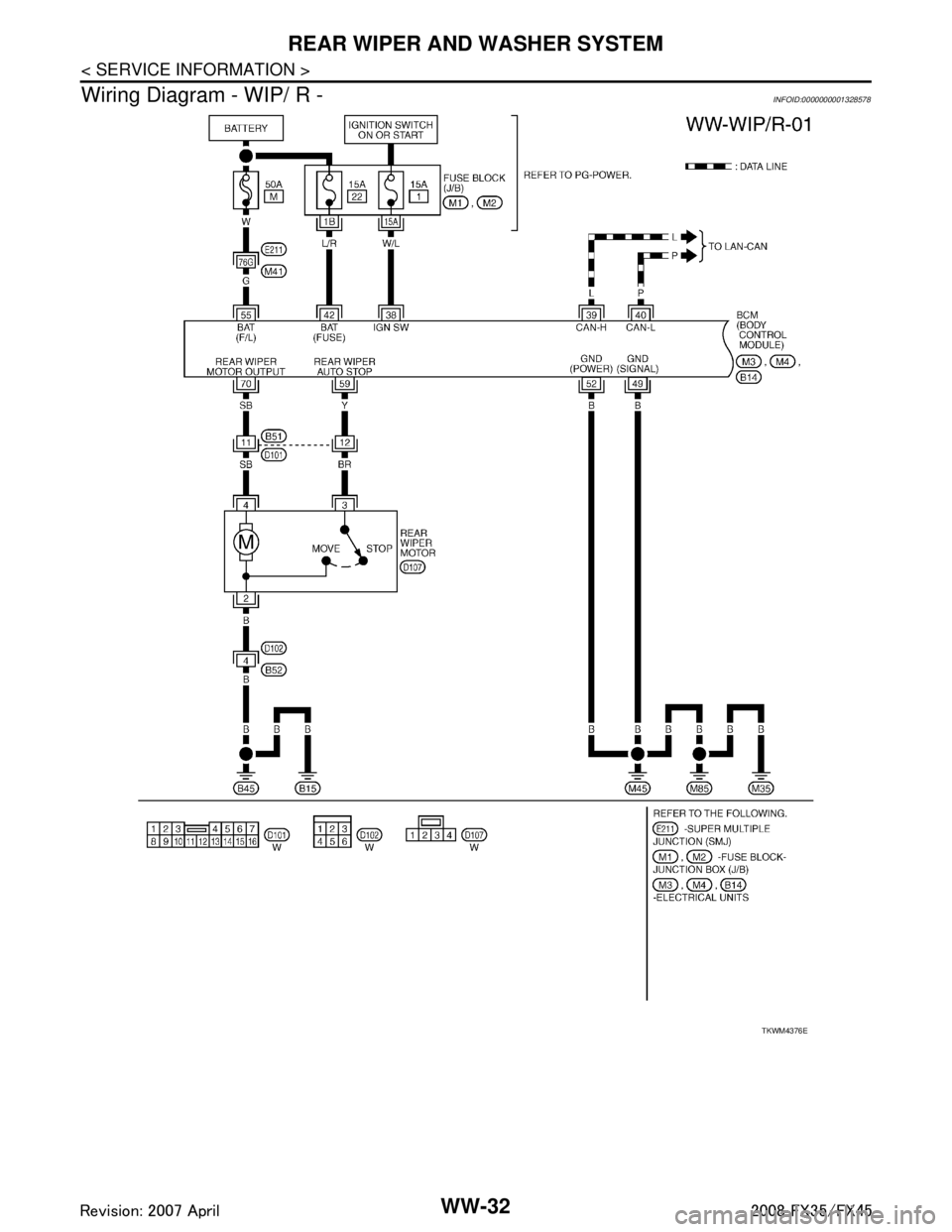
WW-32
< SERVICE INFORMATION >
REAR WIPER AND WASHER SYSTEM
Wiring Diagram - WIP/ R -
INFOID:0000000001328578
TKWM4376E
3AA93ABC3ACD3AC03ACA3AC03AC63AC53A913A773A893A873A873A8E3A773A983AC73AC93AC03AC3
3A893A873A873A8F3A773A9D3AAF3A8A3A8C3A863A9D3AAF3A8B3A8C
Page 3911 of 3924
WW-36
< SERVICE INFORMATION >
REAR WIPER AND WASHER SYSTEM
2. Understand operation description and function description. Refer to WW-30, "System Description".
3. Perform the Preliminary Check. Refer to WW-36, "
Preliminary Check".
4. Check symptom and repair or r eplace the cause of malfunction.
5. Does the rear wiper and washer operate no rmally? If YES, GO TO 6. If NO, GO TO 4.
6. INSPECTION END
Preliminary CheckINFOID:0000000001328581
CHECK POWER SUPPLY AND GROUND CIRCUIT
1.CHECK FUSES
Check for blown fuses.
Refer to WW-32, "Wiring Diagram - WIP/ R -".
OK or NG
OK >> GO TO 2.
NG >> If fuse is blown, be sure to eliminate caus e of malfunction before installing new fuse, Refer to PG-
3, "Schematic".
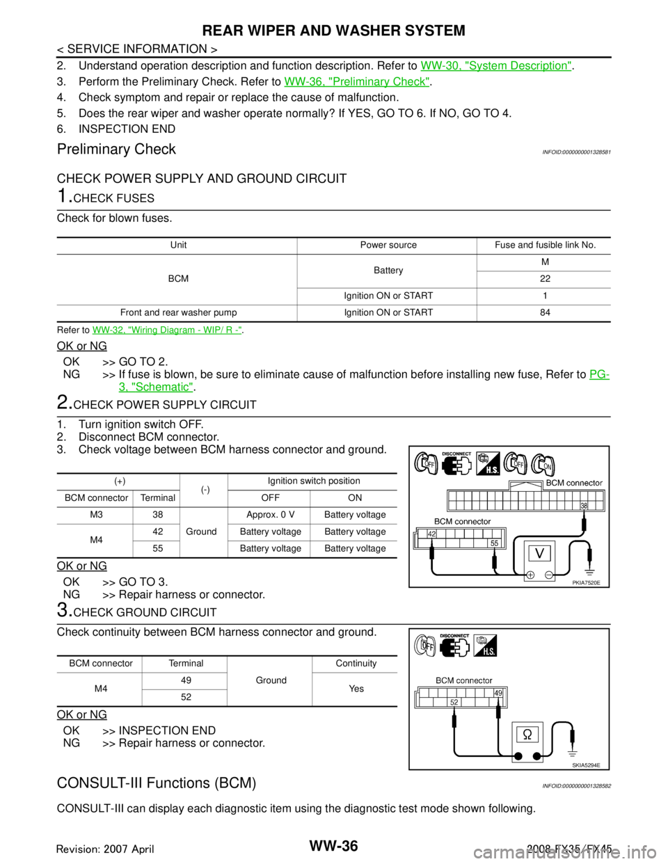
2.CHECK POWER SUPPLY CIRCUIT
1. Turn ignition switch OFF.
2. Disconnect BCM connector.
3. Check voltage between BCM harness connector and ground.
OK or NG
OK >> GO TO 3.
NG >> Repair harness or connector.
3.CHECK GROUND CIRCUIT
Check continuity between BCM harness connector and ground.
OK or NG
OK >> INSPECTION END
NG >> Repair harness or connector.
CONSULT-III Functions (BCM)INFOID:0000000001328582
CONSULT-III can display each diagnostic item using the diagnostic test mode shown following.
Unit Power source Fuse and fusible link No.
BCM BatteryM
22
Ignition ON or START 1
Front and rear washer pump Ignition ON or START 84
(+) (-)Ignition switch position
BCM connector Terminal OFF ON M3 38 GroundApprox. 0 V Battery voltage
M4 42 Battery voltage Battery voltage
55 Battery voltage Battery voltage
PKIA7520E
BCM connector Terminal
GroundContinuity
M4 49
Ye s
52
SKIA5294E
3AA93ABC3ACD3AC03ACA3AC03AC63AC53A913A773A893A873A873A8E3A773A983AC73AC93AC03AC3
3A893A873A873A8F3A773A9D3AAF3A8A3A8C3A863A9D3AAF3A8B3A8C
Page 3920 of 3924
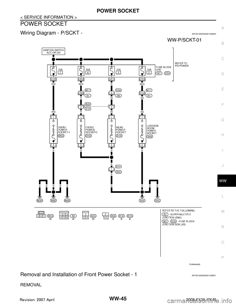
POWER SOCKETWW-45
< SERVICE INFORMATION >
C
DE
F
G H
I
J
L
M A
B
WW
N
O P
POWER SOCKET
Wiring Diagram - P/SCKT -INFOID:0000000001328600
Removal and Installation of Front Power Socket - 1INFOID:0000000001328601
REMOVAL
TKWM4490E
3AA93ABC3ACD3AC03ACA3AC03AC63AC53A913A773A893A873A873A8E3A773A983AC73AC93AC03AC3
3A893A873A873A8F3A773A9D3AAF3A8A3A8C3A863A9D3AAF3A8B3A8C