Page 2791 of 3924
FAX-26
< SERVICE INFORMATION >[AWD]
SERVICE DATA AND SPECIFICATIONS (SDS)
SERVICE DATA AND SPECIFICATIONS (SDS)
Wheel BearingINFOID:0000000001327520
Drive ShaftINFOID:0000000001327521
Axial end play
0.05 mm (0.002 in) or less
Joint Wheel side Front final drive assembly side
Engine type VQ35DE models VK45DE models VQ35DE models VK45DE models
Grease quantityLH side
77 – 97 g (2.71 – 3.42 oz) 95 – 105 g (3.35 – 3.70 oz)
RH side 113 – 123 g (3.98 – 4.33 oz)
Boots installed length LH side
136 mm (5.35 in) 150.9 – 152.9 mm (5.94
– 6.02 in) 95 – 97 mm
(3.74 – 3.82 in)
RH side 157.55 – 159.55 mm (6.20 – 6.28 in)
3AA93ABC3ACD3AC03ACA3AC03AC63AC53A913A773A893A873A873A8E3A773A983AC73AC93AC03AC3
3A893A873A873A8F3A773A9D3AAF3A8A3A8C3A863A9D3AAF3A8B3A8C
Page 2843 of 3924
FUEL TANKFL-11
< SERVICE INFORMATION >
C
DE
F
G H
I
J
K L
M A
FL
NP
O
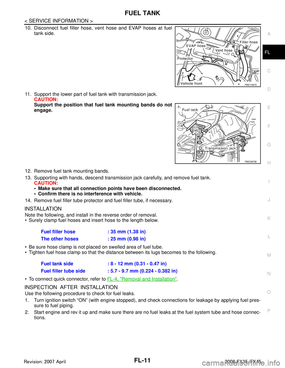
10. Disconnect fuel filler hose, v
ent hose and EVAP hoses at fuel
tank side.
11. Support the lower part of fuel tank with transmission jack. CAUTION:
Support the position that fuel tank mounting bands do not
engage.
12. Remove fuel tank mounting bands.
13. Supporting with hands, descend transmission jack carefully, and remove fuel tank. CAUTION:
Make sure that all connection points have been disconnected.
Confirm there is no interference with vehicle.
14. Remove fuel filler tube protector and fuel filler tube, if necessary.
INSTALLATION
Note the following, and install in the reverse order of removal.
Surely clamp fuel hoses and insert hose to the length below.
Be sure hose clamp is not placed on swelled area of fuel tube.
Tighten fuel hose clamp so that the distance between its lugs becomes to the following.
To connect quick connector, refer to FL-4, "
Removal and Installation".
INSPECTION AFTER INSTALLATION
Use the following procedure to check for fuel leaks.
1. Turn ignition switch “ON” (with engine stopped), and check connections for leakage by applying fuel pres-
sure to fuel piping.
2. Start engine and rev it up and make sure there are no fuel leaks at the fuel system tube and hose connec-
tions.
PBIC1581E
PBIC0878E
Fuel filler hose : 35 mm (1.38 in)
The other hoses : 25 mm (0.98 in)
Fuel tank side : 8 - 12 mm (0.31 - 0.47 in)
Fuel filler tube side : 5.7 - 9.7 mm (0.224 - 0.382 in)
3AA93ABC3ACD3AC03ACA3AC03AC63AC53A913A773A893A873A873A8E3A773A983AC73AC93AC03AC3
3A893A873A873A8F3A773A9D3AAF3A8A3A8C3A863A9D3AAF3A8B3A8C
Page 2868 of 3924
GI-6
< SERVICE INFORMATION >
PRECAUTIONS
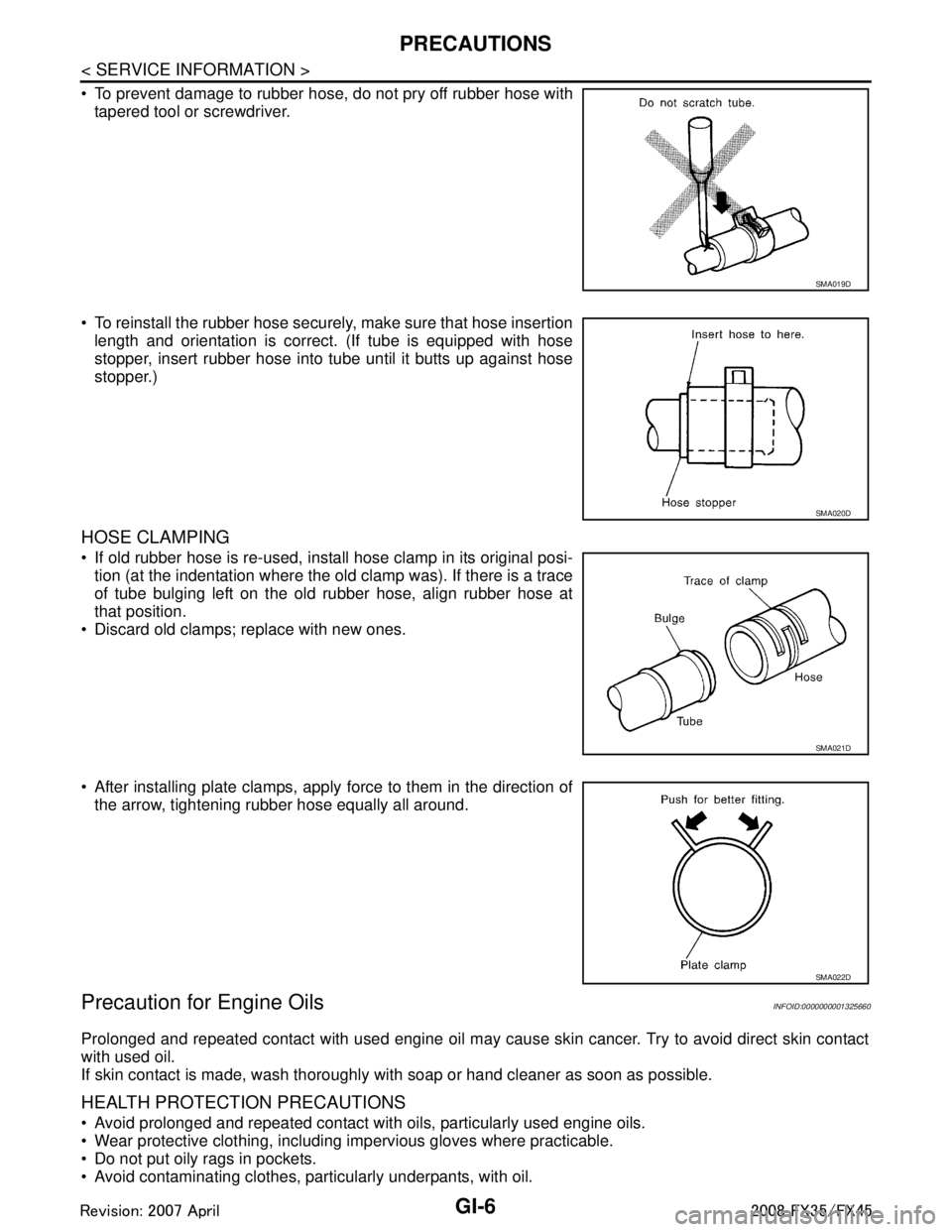
To prevent damage to rubber hose, do not pry off rubber hose withtapered tool or screwdriver.
To reinstall the rubber hose securely, make sure that hose insertion length and orientation is correct. (If tube is equipped with hose
stopper, insert rubber hose into tube until it butts up against hose
stopper.)
HOSE CLAMPING
If old rubber hose is re-used, install hose clamp in its original posi-tion (at the indentation where the old clamp was). If there is a trace
of tube bulging left on the old rubber hose, align rubber hose at
that position.
Discard old clamps; replace with new ones.
After installing plate clamps, apply force to them in the direction of the arrow, tightening rubber hose equally all around.
Precaution for Engine OilsINFOID:0000000001325660
Prolonged and repeated contact with used engine oil may cause skin cancer. Try to avoid direct skin contact
with used oil.
If skin contact is made, wash thoroughly with soap or hand cleaner as soon as possible.
HEALTH PROTECTION PRECAUTIONS
Avoid prolonged and repeated contact with oils, particularly used engine oils.
Wear protective clothing, including impervious gloves where practicable.
Do not put oily rags in pockets.
Avoid contaminating clothes, pa rticularly underpants, with oil.
SMA019D
SMA020D
SMA021D
SMA022D
3AA93ABC3ACD3AC03ACA3AC03AC63AC53A913A773A893A873A873A8E3A773A983AC73AC93AC03AC3
3A893A873A873A8F3A773A9D3AAF3A8A3A8C3A863A9D3AAF3A8B3A8C
Page 2909 of 3924
IDENTIFICATION INFORMATIONGI-47
< SERVICE INFORMATION >
C
DE
F
G H
I
J
K L
M B
GI
N
O PAUTOMATIC TRANSMISSION NUMBER
DimensionsINFOID:0000000001325689
Unit: mm (in)
Wheels & TiresINFOID:0000000001325690
PAIA0054E
Overall length 4,803 (189.1)
Overall width 1,925 (75.8)
Overall height 1,672.6 (65.9)
Front tread 1,592 (62.7)
Rear tread 1,642 (64.6)
Wheelbase 2,850 (112.2)
Application Conventional Spare
Road wheel/offset mm (in) 18 X 8JJ Aluminum/40 (1.57)
20 X 8JJ Aluminum/40 (1.57)
T175/90D18 110M
Tire size P265/60R18 109V
P265/50R20 106V
3AA93ABC3ACD3AC03ACA3AC03AC63AC53A913A773A893A873A873A8E3A773A983AC73AC93AC03AC3
3A893A873A873A8F3A773A9D3AAF3A8A3A8C3A863A9D3AAF3A8B3A8C
Page 3455 of 3924
SERVICE DATA AND SPECIFICATIONS (SDS)
PR-13
< SERVICE INFORMATION >
C EF
G H
I
J
K L
M A
B
PR
N
O P
SERVICE DATA AND SPECIFICATIONS (SDS)
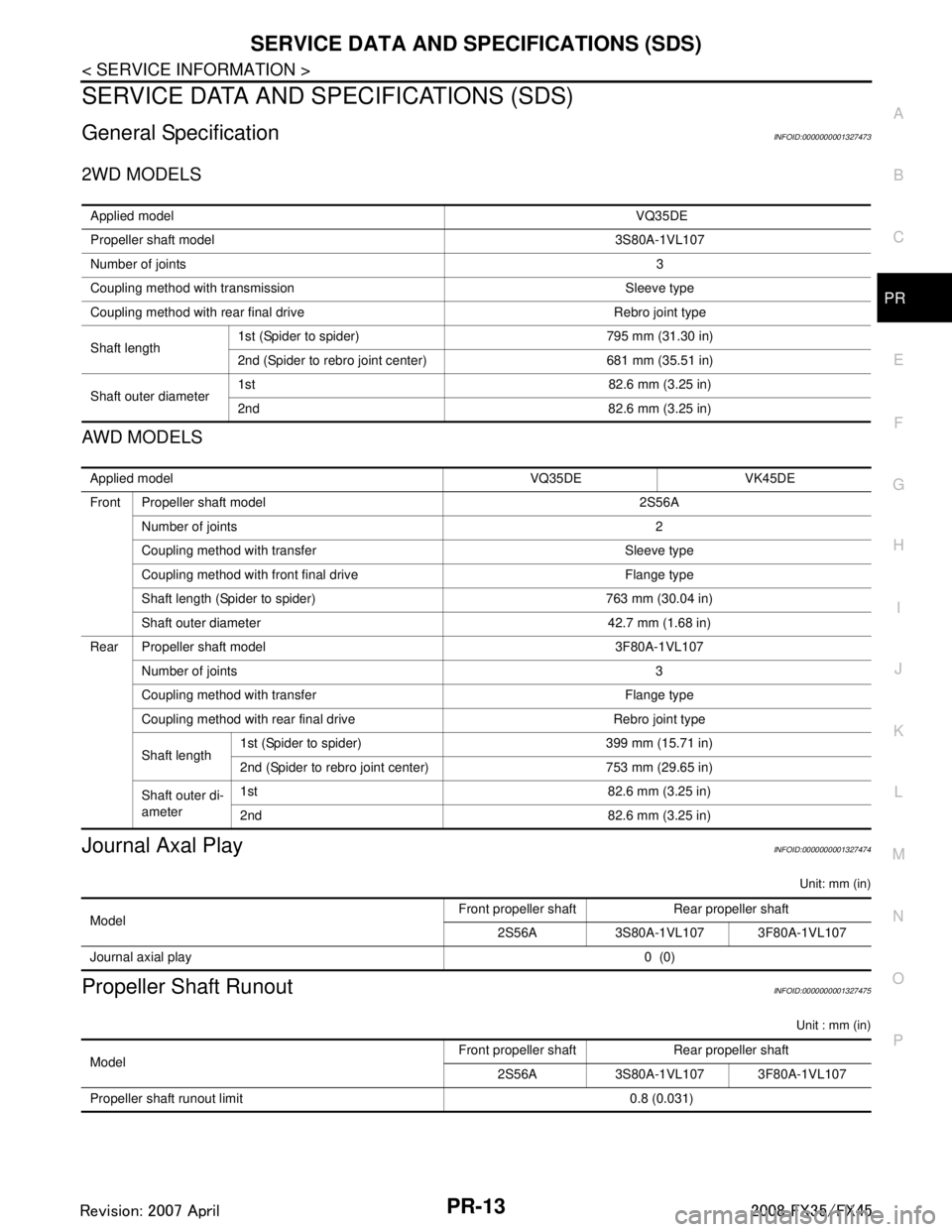
General SpecificationINFOID:0000000001327473
2WD MODELS
AWD MODELS
Journal Axal PlayINFOID:0000000001327474
Unit: mm (in)
Propeller Shaft RunoutINFOID:0000000001327475
Unit : mm (in)
Applied model VQ35DE
Propeller shaft model 3S80A-1VL107
Number of joints 3
Coupling method with transmission Sleeve type
Coupling method with rear final drive Rebro joint type
Shaft length 1st (Spider to spider) 795 mm (31.30 in)
2nd (Spider to rebro joint center) 681 mm (35.51 in)
Shaft outer diameter 1st 82.6 mm (3.25 in)
2nd 82.6 mm (3.25 in)
Applied model VQ35DE VK45DE
Front Propeller shaft model 2S56A
Number of joints 2
Coupling method with transfer Sleeve type
Coupling method with front final drive Flange type
Shaft length (Spider to spider) 763 mm (30.04 in)
Shaft outer diameter 42.7 mm (1.68 in)
Rear Propeller shaft model 3F80A-1VL107 Number of joints 3
Coupling method with transfer Flange type
Coupling method with rear final drive Rebro joint type
Shaft length 1st (Spider to spider) 399 mm (15.71 in)
2nd (Spider to rebro joint center) 753 mm (29.65 in)
Shaft outer di-
ameter 1st 82.6 mm (3.25 in)
2nd 82.6 mm (3.25 in)
Model
Front propeller shaft Rear propeller shaft
2S56A 3S80A-1VL107 3F80A-1VL107
Journal axial play 0 (0)
ModelFront propeller shaft Rear propeller shaft
2S56A 3S80A-1VL107 3F80A-1VL107
Propeller shaft runout limit 0.8 (0.031)
3AA93ABC3ACD3AC03ACA3AC03AC63AC53A913A773A893A873A873A8E3A773A983AC73AC93AC03AC3
3A893A873A873A8F3A773A9D3AAF3A8A3A8C3A863A9D3AAF3A8B3A8C
Page 3469 of 3924
PS-14
< SERVICE INFORMATION >
STEERING COLUMN
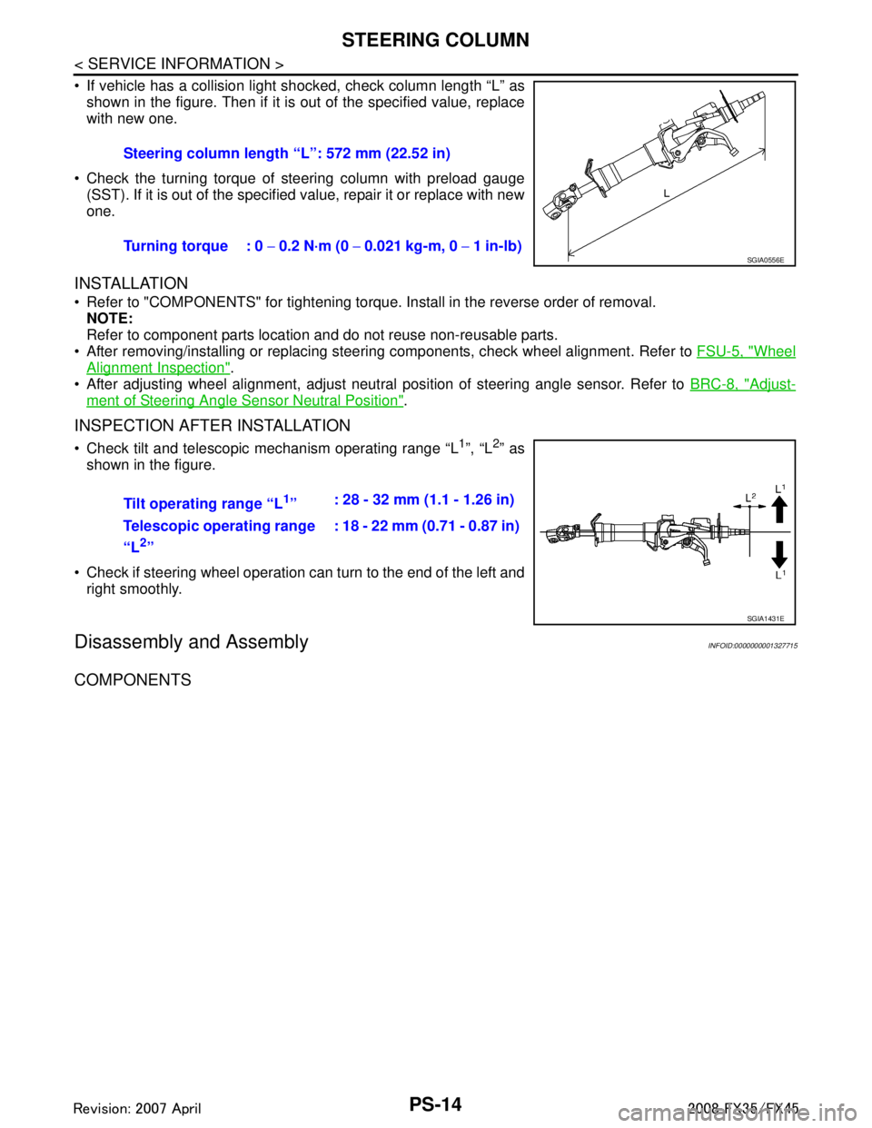
If vehicle has a collision light shocked, check column length “L” as
shown in the figure. Then if it is out of the specified value, replace
with new one.
Check the turning torque of steering column with preload gauge (SST). If it is out of the specified value, repair it or replace with new
one.
INSTALLATION
Refer to "COMPONENTS" for tightening torque. Install in the reverse order of removal.NOTE:
Refer to component parts location and do not reuse non-reusable parts.
After removing/installing or replacing steering components, check wheel alignment. Refer to FSU-5, "
Wheel
Alignment Inspection".
After adjusting wheel alignment, adjust neutral position of steering angle sensor. Refer to BRC-8, "
Adjust-
ment of Steering Angle Sensor Neutral Position".
INSPECTION AFTER INSTALLATION
Check tilt and telescopic mechanism operating range “L1”, “L2” as
shown in the figure.
Check if steering wheel operation can turn to the end of the left and right smoothly.
Disassembly and AssemblyINFOID:0000000001327715
COMPONENTS
Steering column length “L”: 572 mm (22.52 in)
Turning torque : 0 − 0.2 N·m (0 − 0.021 kg-m, 0 − 1 in-lb)
SGIA0556E
Tilt operating range “L1” : 28 - 32 mm (1.1 - 1.26 in)
Telescopic operating range
“L
2” : 18 - 22 mm (0.71 - 0.87 in)
SGIA1431E
3AA93ABC3ACD3AC03ACA3AC03AC63AC53A913A773A893A873A873A8E3A773A983AC73AC93AC03AC3
3A893A873A873A8F3A773A9D3AAF3A8A3A8C3A863A9D3AAF3A8B3A8C
Page 3481 of 3924
PS-26
< SERVICE INFORMATION >
POWER STEERING GEAR AND LINKAGE
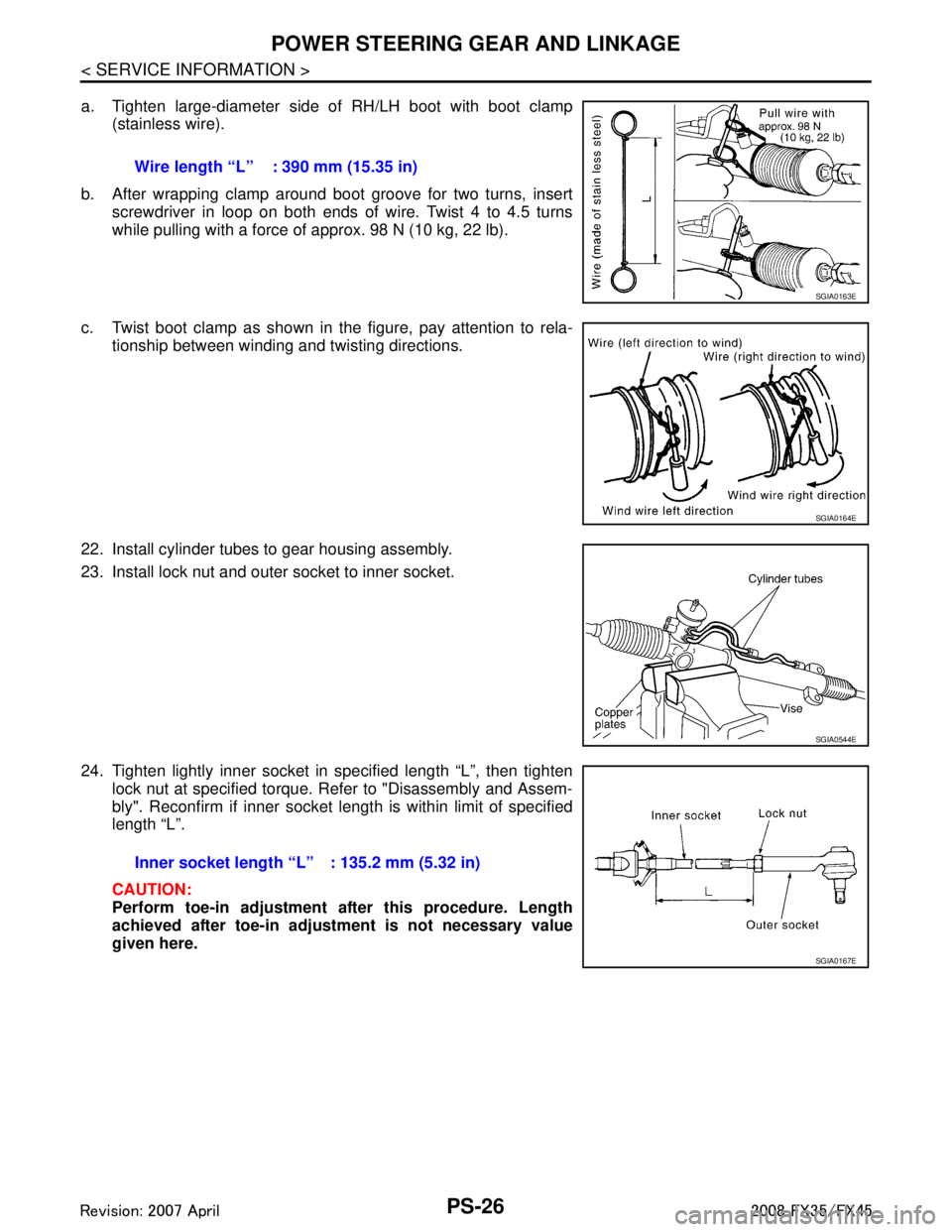
a. Tighten large-diameter side of RH/LH boot with boot clamp(stainless wire).
b. After wrapping clamp around boot groove for two turns, insert screwdriver in loop on both ends of wire. Twist 4 to 4.5 turns
while pulling with a force of approx. 98 N (10 kg, 22 lb).
c. Twist boot clamp as shown in the figure, pay attention to rela- tionship between winding and twisting directions.
22. Install cylinder tubes to gear housing assembly.
23. Install lock nut and outer socket to inner socket.
24. Tighten lightly inner socket in specified length “L”, then tighten lock nut at specified torque. Refer to "Disassembly and Assem-
bly". Reconfirm if inner socket length is within limit of specified
length “L”.
CAUTION:
Perform toe-in adjustment after this procedure. Length
achieved after toe-in adjustment is not necessary value
given here.Wire length “L” : 390 mm (15.35 in)
SGIA0163E
SGIA0164E
SGIA0544E
Inner socket length “L” : 135.2 mm (5.32 in)
SGIA0167E
3AA93ABC3ACD3AC03ACA3AC03AC63AC53A913A773A893A873A873A8E3A773A983AC73AC93AC03AC3
3A893A873A873A8F3A773A9D3AAF3A8A3A8C3A863A9D3AAF3A8B3A8C
Page 3496 of 3924
SERVICE DATA AND SPECIFICATIONS (SDS)
PS-41
< SERVICE INFORMATION >
C
D E
F
H I
J
K L
M A
B
PS
N
O P
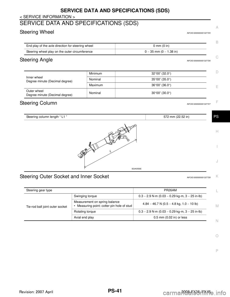
SERVICE DATA AND SPECIFICATIONS (SDS)
Steering WheelINFOID:0000000001327725
Steering AngleINFOID:0000000001327726
Steering ColumnINFOID:0000000001327727
Steering Outer Socket and Inner SocketINFOID:0000000001327728
End play of the axle direction for steering wheel 0 mm (0 in)
Steering wheel play on the outer circumference 0 − 35 mm (0 − 1.38 in)
Inner wheel
Degree minute (Decimal degree) Minimum 32
°00 ′ (32.0 °)
Nominal 35 °00 ′ (35.0 °)
Maximum 36 °00 ′ (36.0 °)
Outer wheel
Degree minute (Decimal degree) Nominal 30
°00 ′ (30.0 °)
Steering column length “ L1 ” 572 mm (22.52 in)
SGIA0556E
Steering gear type PR26AM
Tie-rod ball joint outer socket Swinging torque 0.3
− 2.9 N·m (0.03 − 0.29 kg-m, 3 − 25 in-lb)
Measurement on spring balance
Measuring point: cotter pin hole of stud 4.84
− 46.7 N (0.5 − 4.8 kg, 1.0 − 10 lb)
Rotating torque 0.3 − 2.9 N·m (0.03 − 0.29 kg-m, 3 − 25 in-lb)
Axial end play 0.5 mm (0.02 in) or less
3AA93ABC3ACD3AC03ACA3AC03AC63AC53A913A773A893A873A873A8E3A773A983AC73AC93AC03AC3
3A893A873A873A8F3A773A9D3AAF3A8A3A8C3A863A9D3AAF3A8B3A8C