2008 INFINITI FX35 horn
[x] Cancel search: hornPage 3383 of 3924

IPDM E/R (INTELLIGENT POWER DISTRIBUTION MODULE ENGINE ROOM)
PG-19
< SERVICE INFORMATION >
C
D E
F
G H
I
J
L
M A
B
PG
N
O P
NOTE: The details for display of the period are as follows:
CRNT: Error currently de tected with IPDM E/R.
PAST: Error detected in the past and memorized with IPDM E/R.
DATA MONITOR
NOTE:
Perform monitoring of IPDM E/R data with the ignition switch ON. When the ignition switch is at ACC, the display may not be co rrect.
*1: The vehicle without the Intelligent Key system displays only ON without change.
*2:The cornering lamp item is displayed, but it cannot be monitored.
ACTIVE TEST
DTC Display Items Malfunction detecting condition TIME
Possible causes
CRNT PAST
— NO DTC IS DETECT-
ED.FURTHER TEST-
ING MAY BE
REQUIRED. ————
U1000 CAN COMM CIRCUIT If CAN communication reception/transmission
data has a malfunction, or if any of the control
units malfunction, data reception/transmission
cannot be confirmed.
When the data in CAN communication is not re- ceived before the specified time ××
Any of or several items
below have errors.
TRANSMIT DIAG
ECM
BCM/SEC
Item name
CONSULT-III screen dis-
play Display or unit MAIN SIG-
NALS Description
Motor fan request MOTOR FAN REQ 1/2/3/4 ×Signal status input from ECM
Compressor request A C COMP REQ On/Off ×Signal status input from ECM
Tail & clear request TAIL&CLR REQ On/Off ×Signal status input from BCM
H/L LO request HL LO REQ On/Off ×Signal status input from BCM
H/L HI request HL HI REQ On/Off ×Signal status input from BCM
FR fog request FR FOG REQ On/Off ×Signal status input from BCM
FR wiper request FR WIP REQ Stop/1LOW/Lo/Hi ×Signal status input from BCM
Wiper auto stop WIP AUTO STOP ACT P/STOP P ×Output status of IPDM E/R
Wiper protection WIP PROT Off/BLOCK ×Control status of IPDM E/R
Starter request ST RLY REQ
*1On/Off Status of input signal
Ignition relay status IGN RLY On/Off ×Ignition relay status monitored with
IPDM E/R
Rear window defogger re-
quest RR DEF REQ On/Off
×Signal status input from BCM
Oil pressure switch OIL P SW Open/Close Signal status input in IPDM E/R
Hood switch HOOD SW On/Off Input signal status
Theft warning horn re-
quest THFT HRN REQ On/Off Signal st
atus input from BCM
Horn chirp HORN CHIRP On/Off Ou tput status of IPDM E/R
Cornering lamp request CRNRNG LMP REQ
*2Off Signal status input from BCM
Test item CONSULT-III screen display Description
Tail lamp operation TAIL LAMP With a certain On-Off operation, the tail lamp relay can be operated.
Rear window defogger opera-
tion REAR DEFOGGER
With a certain On-Off operation, the rear window defogger relay can be
operated.
3AA93ABC3ACD3AC03ACA3AC03AC63AC53A913A773A893A873A873A8E3A773A983AC73AC93AC03AC3
3A893A873A873A8F3A773A9D3AAF3A8A3A8C3A863A9D3AAF3A8B3A8C
Page 3384 of 3924

PG-20
< SERVICE INFORMATION >
IPDM E/R (INTELLIGENT POWER DISTRIBUTION MODULE ENGINE ROOM)
NOTE:
This item is displayed, but cannot be tested.
Auto Active TestINFOID:0000000001328875
DESCRIPTION
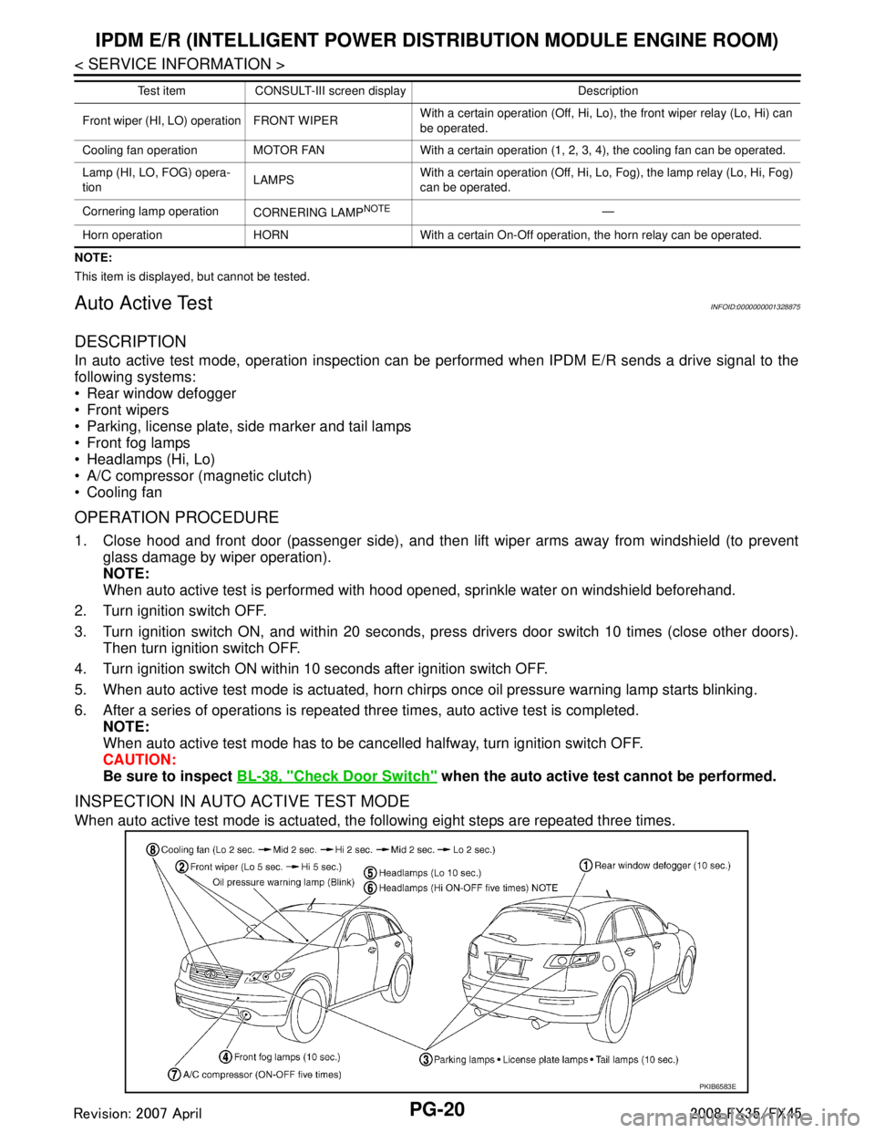
In auto active test mode, operation inspection can be performed when IPDM E/R sends a drive signal to the
following systems:
Rear window defogger
Front wipers
Parking, license plate, side marker and tail lamps
Front fog lamps
Headlamps (Hi, Lo)
A/C compressor (magnetic clutch)
Cooling fan
OPERATION PROCEDURE
1. Close hood and front door (passenger side), and then lift wiper arms away from windshield (to prevent
glass damage by wiper operation).
NOTE:
When auto active test is performed with hood opened, sprinkle water on windshield beforehand.
2. Turn ignition switch OFF.
3. Turn ignition switch ON, and within 20 seconds, pre ss drivers door switch 10 times (close other doors).
Then turn ignition switch OFF.
4. Turn ignition switch ON within 10 seconds after ignition switch OFF.
5. When auto active test mode is actuated, horn chir ps once oil pressure warning lamp starts blinking.
6. After a series of operations is repeated three times, auto active test is completed. NOTE:
When auto active test mode has to be cancelled halfway, turn ignition switch OFF.
CAUTION:
Be sure to inspect BL-38, "
Check Door Switch" when the auto active t est cannot be performed.
INSPECTION IN AUTO ACTIVE TEST MODE
When auto active test mode is actuated, the following eight steps are repeated three times.
Front wiper (HI, LO) operation FRONT WIPER With a certain operation (Off, Hi, Lo),
the front wiper relay (Lo, Hi) can
be operated.
Cooling fan operation MOTOR FAN With a certain operation (1, 2, 3, 4), the cooling fan can be operated.
Lamp (HI, LO, FOG) opera-
tion LAMPSWith a certain operation (Off, Hi, Lo, Fog), the lamp relay (Lo, Hi, Fog)
can be operated.
Cornering lamp operation CORNERING LAMP
NOTE—
Horn operation HORN With a certain On-Off operation, the horn relay can be operated. Test item CONSULT-III screen display Description
PKIB6583E
3AA93ABC3ACD3AC03ACA3AC03AC63AC53A913A773A893A873A873A8E3A773A983AC73AC93AC03AC3
3A893A873A873A8F3A773A9D3AAF3A8A3A8C3A863A9D3AAF3A8B3A8C
Page 3426 of 3924

PG-62
< SERVICE INFORMATION >
HARNESS
H/AIM LT Headlamp Aiming Control System
H/LAMP LT Headlamp
H/PHON AV Hands Free Telephone
HORN WW Horn
HSEAT SE Heated Seat
I/KEY BL Intelligent Key System
I/MIRR GW Inside Mirror (Auto Anti-Dazzling Mirror)
IATS EC Intake Air Temperature Sensor
ICC ACS Intelligent Cruise Control System
ICC/BS EC ICC Brake Switch
ICC/SW EC ICC Steering Switch
ICCBOF EC ICC Brake Switch
IGNSYS EC Ignition System
ILL LT Illumination
INF/D AV Vehicle Information and Integrated Switch System
INJECT EC Injector
IVCB1 EC Intake Valve Timing Control Solenoid Valve Bank 1
IVCB2 EC Intake Valve Timing Control Solenoid Valve Bank 2
IVCSB1 EC Intake Valve Timing Control Position Sensor Bank 1
IVCSB2 EC Intake Valve Timing Control Position Sensor Bank 2
IVTB1 EC Intake Valve Timing Control System (Bank 1)
IVTB2 EC Intake Valve Timing Control System (Bank 2)
KEYLES BL Remote Keyless Entry System
KS EC Knock Sensor
LDW DI Lane Departure Warning System
M/ANT AV Manual Antenna
MAFS EC Mass Air Flow Sensor
MAIN AT Main Power Supply and Ground Circuit
MAIN EC Main Power Supply and Ground Circuit
MES AV Mobile Entertainment System
METER DI Speedometer, Tachometer, Temp. and Fuel Gauges
MIL/DL EC MIL & Data Link Connector
MIRROR GW Power Door Mirror
MMSW AT Manual Mode Switch
NATS BL Nissan Anti-Theft System
NAVI AV Navigation System
NONDTC AT Non-Detective Items
O2H2B1 EC Heated Oxygen Sensor 2 Heater Bank 1
O2H2B2 EC Heated Oxygen Sensor 2 Heater Bank 2
O2S2B1 EC Heated Oxygen Sensor 2 Bank 1
O2S2B2 EC Heated Oxygen Sensor 2 Bank 2
P/SCKT WW Power Socket
PGC/V EC EVAP Canister Purge Volume Control Solenoid Valve
PHASE EC Camshaft Position Sensor (PHASE) Code Section Wiri
ng Diagram Name
3AA93ABC3ACD3AC03ACA3AC03AC63AC53A913A773A893A873A873A8E3A773A983AC73AC93AC03AC3
3A893A873A873A8F3A773A9D3AAF3A8A3A8C3A863A9D3AAF3A8B3A8C
Page 3773 of 3924

SRS-36
< SERVICE INFORMATION >
SPIRAL CABLE
SPIRAL CABLE
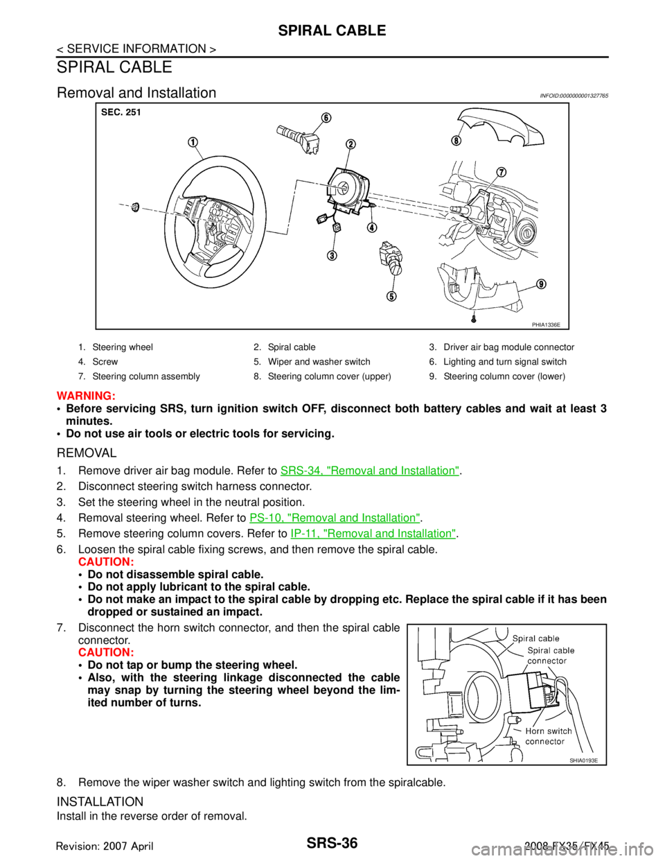
Removal and InstallationINFOID:0000000001327765
WARNING:
Before servicing SRS, turn ignition switch OFF, disconnect both ba ttery cables and wait at least 3
minutes.
Do not use air tools or el ectric tools for servicing.
REMOVAL
1. Remove driver air bag module. Refer to SRS-34, "Removal and Installation".
2. Disconnect steering switch harness connector.
3. Set the steering wheel in the neutral position.
4. Removal steering wheel. Refer to PS-10, "
Removal and Installation".
5. Remove steering column covers. Refer to IP-11, "
Removal and Installation".
6. Loosen the spiral cable fixing screws, and then remove the spiral cable. CAUTION:
Do not disassemble spiral cable.
Do not apply lubricant to the spiral cable.
Do not make an impact to the spiral cable by dro pping etc. Replace the spiral cable if it has been
dropped or sustained an impact.
7. Disconnect the horn switch connec tor, and then the spiral cable
connector.
CAUTION:
Do not tap or bump the steering wheel.
Also, with the steering li nkage disconnected the cable
may snap by turning the st eering wheel beyond the lim-
ited number of turns.
8. Remove the wiper washer switch and lighting switch from the spiralcable.
INSTALLATION
Install in the reverse order of removal.
PHIA1336E
1. Steering wheel 2. Spiral cable 3. Driver air bag module connector
4. Screw 5. Wiper and washer switch 6. Lighting and turn signal switch
7. Steering column assembly 8. Steering column cover (upper) 9. Steering column cover (lower)
SHIA0193E
3AA93ABC3ACD3AC03ACA3AC03AC63AC53A913A773A893A873A873A8E3A773A983AC73AC93AC03AC3
3A893A873A873A8F3A773A9D3AAF3A8A3A8C3A863A9D3AAF3A8B3A8C
Page 3862 of 3924

WT-22
< SERVICE INFORMATION >
TROUBLE DIAGNOSES
NOTE:
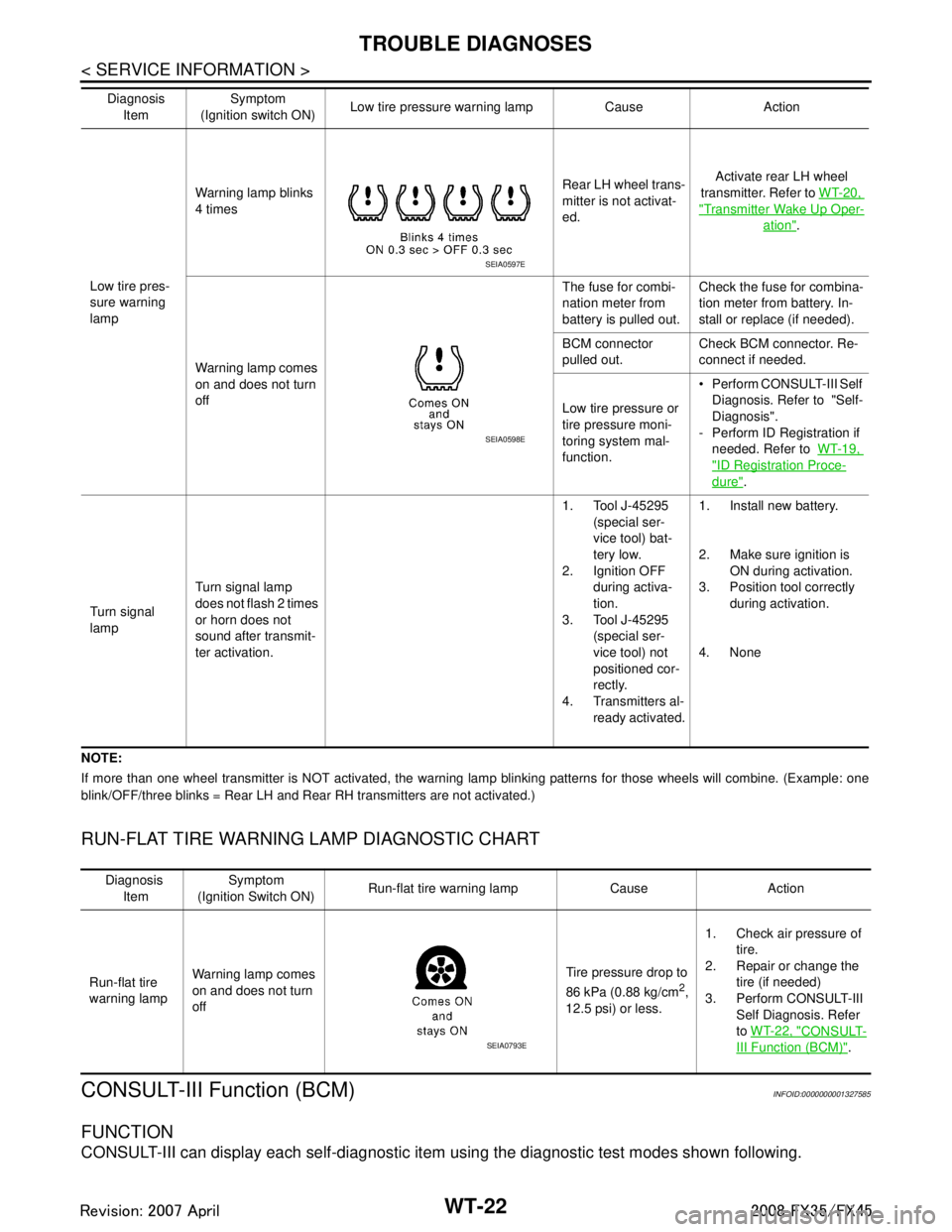
If more than one wheel transmitter is NOT activated, the warning lamp blinking patterns for those wheels will combine. (Example: one
blink/OFF/three blinks = Rear LH and Rear RH transmitters are not activated.)
RUN-FLAT TIRE WARNING LAMP DIAGNOSTIC CHART
CONSULT-III Function (BCM)INFOID:0000000001327585
FUNCTION
CONSULT-III can display each self-diagnostic item using the diagnostic test modes shown following.
Low tire pres-
sure warning
lampWarning lamp blinks
4 times
Rear LH wheel trans-
mitter is not activat-
ed.Activate rear LH wheel
transmitter. Refer to WT-20,
"Transmitter Wake Up Oper-
ation".
Warning lamp comes
on and does not turn
off The fuse for combi-
nation meter from
battery is pulled out.
Check the fuse for combina-
tion meter from battery. In-
stall or replace (if needed).
BCM connector
pulled out. Check BCM connector. Re-
connect if needed.
Low tire pressure or
tire pressure moni-
toring system mal-
function. Perform CONSULT-III Self
Diagnosis. Refer to "Self-
Diagnosis".
- Perform ID Registration if needed. Refer to WT-19,
"ID Registration Proce-
dure".
Turn signal
lamp Turn signal lamp
does not flash 2 times
or horn does not
sound after transmit-
ter activation. 1. Tool J-45295
(special ser-
vice tool) bat-
tery low.
2. Ignition OFF
during activa-
tion.
3. Tool J-45295
(special ser-
vice tool) not
positioned cor-
rectly.
4. Transmitters al- ready activated. 1. Install new battery.
2. Make sure ignition is
ON during activation.
3. Position tool correctly during activation.
4. None
Diagnosis
Item Symptom
(Ignition switch ON) Low tire pressure wa
rning lamp Cause Action
SEIA0597E
SEIA0598E
Diagnosis
Item Symptom
(Ignition Switch ON) Run-flat tire warning lamp Cause Action
Run-flat tire
warning lamp Warning lamp comes
on and does not turn
off Tire pressure drop to
86 kPa (0.88 kg/cm
2,
12.5 psi) or less. 1. Check air pressure of
tire.
2. Repair or change the
tire (if needed)
3. Perform CONSULT-III Self Diagnosis. Refer
to WT-22, "
CONSULT-
III Function (BCM)".SEIA0793E
3AA93ABC3ACD3AC03ACA3AC03AC63AC53A913A773A893A873A873A8E3A773A983AC73AC93AC03AC3
3A893A873A873A8F3A773A9D3AAF3A8A3A8C3A863A9D3AAF3A8B3A8C
Page 3864 of 3924

WT-24
< SERVICE INFORMATION >
TROUBLE DIAGNOSES
NOTE:
Before performing the self-diagnosis, be sure to register the ID, or else the actual malfunction location may be different from that dis-
played on CONSULT-III.
ACTIVE TEST MODE
Test Item
Flasher
Horn
Warning lamp
ID regist warning
Flat tire warning
How to Perform Trouble Diagnosis for Quick and Accurate RepairINFOID:0000000001327586
INTRODUCTION
Before troubleshooting, verify customer complaints.
If a vehicle malfunction is difficult to reproduce, harnesses, harness connectors or terminals may be mal-
functioning. Hold and shake these parts to make sure they are securely connected.
When using a circuit tester to measure voltage or re sistance of each circuit, be careful not to damage or
deform connector terminals.
WORK FLOW
MONITOR CONDITION SPECIFICATION
VEHICLE SPEED Drive vehicle. V ehicle speed (km/h or MPH)
AIR PRESS FL
AIR PRESS FR
AIR PRESS RR
AIR PRESS RL Drive vehicle for a few minutes.
Tire pressure (kPa or Psi)
or
Ignition switch ON and activation tool is transmitting activation signals.
ID REGST FL 1
ID REGST FR 1
ID REGST RR 1
ID REGST RL 1 Ignition switch ON Registration ID: DONE
No registration ID: YET
WARNING LAMP Low tire pressure
warning lamp on: ON
Low tire pressure wa rning lamp off: OFF
BUZZER Buzzer in combination meter on: ON
Buzzer in combination meter off: OFF
3AA93ABC3ACD3AC03ACA3AC03AC63AC53A913A773A893A873A873A8E3A773A983AC73AC93AC03AC3
3A893A873A873A8F3A773A9D3AAF3A8A3A8C3A863A9D3AAF3A8B3A8C
Page 3876 of 3924

WW-1
ELECTRICAL
C
DE
F
G H
I
J
L
M
SECTION WW
A
B
WW
N
O P
CONTENTS
WIPER, WASHER & HORN
SERVICE INFORMATION .. ..........................3
PRECAUTION ................................................ .....3
Precaution for Supplemental Restraint System
(SRS) "AIR BAG" and "SEAT BELT PRE-TEN-
SIONER" ............................................................. ......
3
Precaution for Procedure without Cowl Top Cover ......3
FRONT WIPER AND WASHER SYSTEM ..........4
Component Parts and Harness Connector Loca-
tion ...................................................................... ......
4
System Description ...................................................4
CAN Communication System Description .................6
CAN Communication Unit .........................................7
Schematic .................................................................7
Wiring Diagram - WIPER - ........................................8
Terminal and Reference Value for BCM .................10
Terminal and Reference Value for IPDM E/R .........14
How to Proceed with Trouble Diagnosis .................14
Preliminary Check ...................................................14
CONSULT-III Functions (BCM) ...............................15
CONSULT-III Functions (IPDM E/R) .......................16
Front Wiper Does Not Operate ...............................17
Front Wiper Does Not Return to Stop Position .......18
Only Front Wiper Low Does Not Operate ...............19
Only Front Wiper High Does Not Operate ...............20
Only Front Wiper Intermittent Does Not Operate ....21
Front Wiper Interval Time Is Not Controlled by Ve-
hicle Speed .............................................................
21
Front Wiper Intermittent Operation Switch Posi-
tion Cannot Be Adjusted .........................................
22
Wiper Does Not Wipe When Front Washer Oper-
ates .........................................................................
22
After Front Wiper Operate for 10 Seconds, They
Stop for 20 Seconds, and After Repeating the Op-
eration Five Times, They Become Inoperative ........
22
Front Wiper Does Not Stop .....................................23
Removal and Installation of Front Wiper Arms, Ad-
justment of Wiper Arms Stop Location ....................
23
Removal and Installation of Front Wiper Drive As-
sembly ................................................................. ....
24
Disassembly and Assembly of Front Wiper Drive
Assembly ............................................................. ....
25
Washer Nozzle Adjustment .....................................25
Washer Tube Layout ...............................................27
Removal and Installation of Front Washer Nozzle ....27
Removal and Installation of Front Washer Tube
Joint .........................................................................
27
Inspection of Washer Nozzle ...................................27
Inspection of Front Wiper and Washer Switch Cir-
cuit ...........................................................................
28
Removal and Installation of Front Wiper and
Washer Switch .........................................................
28
Removal and Installation of Washer Tank ...............28
Removal and Installation of Front and Rear Wash-
er Pump ...................................................................
29
REAR WIPER AND WASHER SYSTEM ..........30
Component Parts and Harness Connector Loca-
tion ...........................................................................
30
System Description ..................................................30
Wiring Diagram - WIP/ R - .......................................32
Terminal and Reference Value for BCM ..................33
How to Proceed with Trouble Diagnosis ..................35
Preliminary Check ...................................................36
CONSULT-III Functions (BCM) ...............................36
Rear Wiper Does Not Operate ................................37
Rear Wiper Does Not Return to Stop Position ........39
Only Rear Wiper ON Does Not Operate ..................40
Only Rear Wiper INT Does Not Operate .................40
Wiper Does Not Wipe When Rear Washer Oper-
ates ..........................................................................
40
Rear Wipers Do Not Stop ........................................40
Removal and Installation of Rear Wiper Arm, Ad-
justment of Wiper Arms Stop Location ....................
40
Removal and Installation of Rear Wiper Blade ........41
Removal and Installation of Rear Wiper Motor ........42
Washer Nozzle Adjustment .....................................43
Washer Tube Layout ...............................................43
Removal and Installation of Washer Nozzle ............43
Check Valve ............................................................44
3AA93ABC3ACD3AC03ACA3AC03AC63AC53A913A773A893A873A873A8E3A773A983AC73AC93AC03AC3
3A893A873A873A8F3A773A9D3AAF3A8A3A8C3A863A9D3AAF3A8B3A8C
Page 3877 of 3924

WW-2
Inspection of Front Wiper and Washer Switch Cir-
cuit ..........................................................................
44
Removal and Installation of Rear Wiper and
Washer Switch ........................................................
44
Removal and Installation of Washer Tank ..............44
Removal and Installation of Front and Rear Wash-
er pump ..................................................................
44
POWER SOCKET ..............................................45
Wiring Diagram - P/SCKT - ................................. ...45
Removal and Installation of Front Power Socket -
1 ........................................................................... ...
45
Removal and Installation of Front Power Socket -
2 ..............................................................................
46
Removal and Installation of Rear Power Socket .....46
Removal and Installation of Luggage Room Power
Socket .................................................................. ...
46
HORN .................................................................48
Wiring Diagram - HORN - .................................... ...48
Removal and Installation .........................................48
3AA93ABC3ACD3AC03ACA3AC03AC63AC53A913A773A893A873A873A8E3A773A983AC73AC93AC03AC3
3A893A873A873A8F3A773A9D3AAF3A8A3A8C3A863A9D3AAF3A8B3A8C