2008 INFINITI FX35 change wheel
[x] Cancel search: change wheelPage 3676 of 3924
AUTOMATIC DRIVE POSITIONERSE-37
< SERVICE INFORMATION >
C
DE
F
G H
J
K L
M A
B
SE
N
O P
Work FlowINFOID:0000000001328106
1. Check the symptom and customer's requests.
2. Understand the system description. Refer to SE-12, "
System Description".
3. Perform the preliminary check, refer to SE-37, "
Preliminary Check".
4. Perform the CAN communication inspec tion using CONSULT-III, refer to SE-40, "
CONSULT-III Function
(AUTO DRIVE POS.)".
5. Perform the self-diagnosis. Refer to SE-42, "
Check CAN Communication System".
6. Repair or replace depending on the self-diagnostic results.
7. Based on the trouble diagnosis chart, repair or replace the cause of the malfunction. Refer to SE-43,
"Symptom Chart".
8. Does the automatic drive pos itioner system operate normally?
If it is normal, GO TO 8.
If it is not normal, GO TO 3.
9. INSPECTION END
Preliminary CheckINFOID:0000000001328107
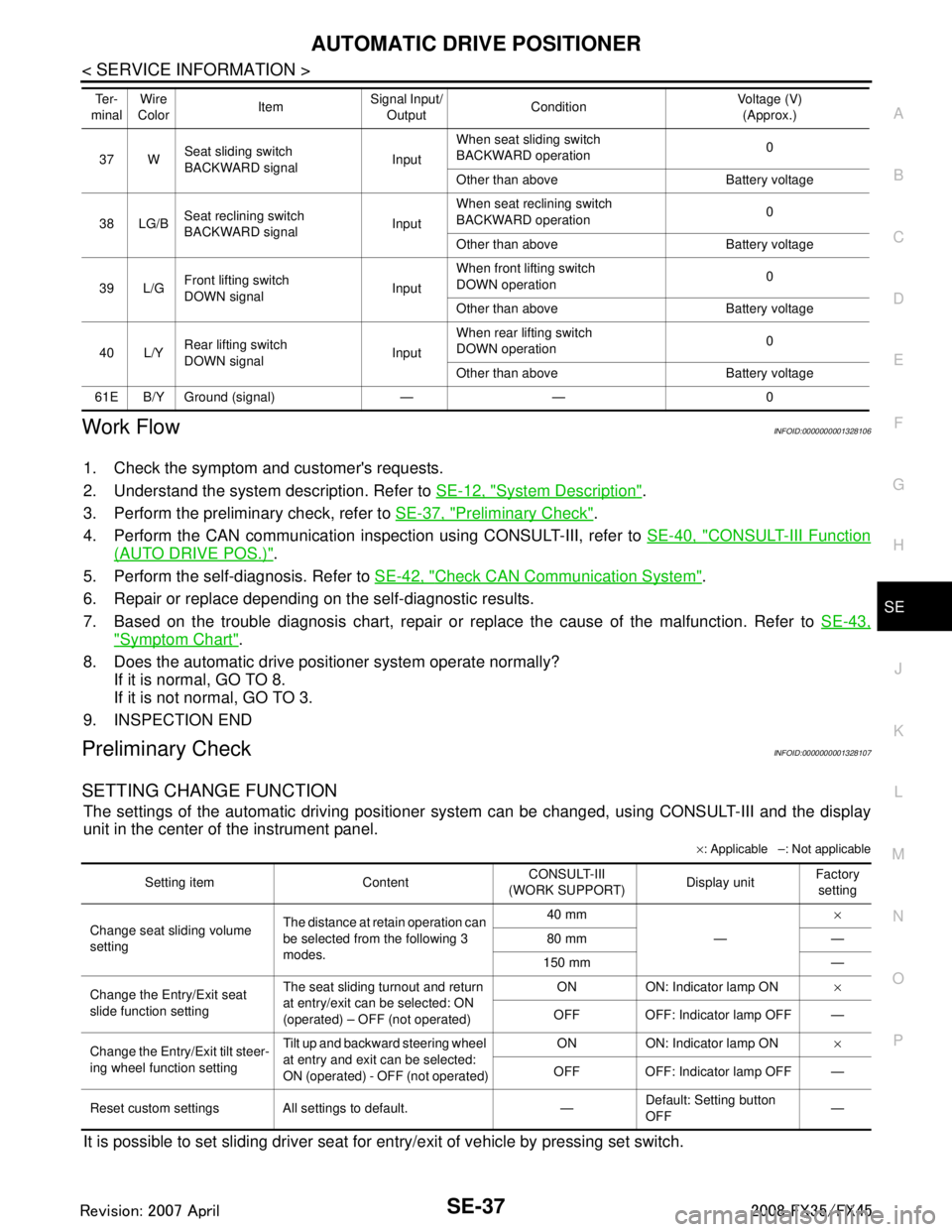
SETTING CHANGE FUNCTION
The settings of the automatic driving positioner system can be changed, using CONSULT-III and the display
unit in the center of the instrument panel.
× : Applicable –: Not applicable
It is possible to set sliding driver seat fo r entry/exit of vehicle by pressing set switch.
37 WSeat sliding switch
BACKWARD signal
InputWhen seat sliding switch
BACKWARD operation
0
Other than above Battery voltage
38 LG/B Seat reclining switch
BACKWARD signal InputWhen seat reclining switch
BACKWARD operation
0
Other than above Battery voltage
39 L/G Front lifting switch
DOWN signal InputWhen front lifting switch
DOWN operation
0
Other than above Battery voltage
40 L/Y Rear lifting switch
DOWN signal
InputWhen rear lifting switch
DOWN operation
0
Other than above Battery voltage
61E B/Y Ground (signal) — — 0 Te r -
minal Wire
Color ItemSignal Input/
Output Condition Voltage (V)
(Approx.)
Setting item Content CONSULT-III
(WORK SUPPORT) Display unitFactory
setting
Change seat sliding volume
setting The distance at retain operation can
be selected from the following 3
modes. 40 mm
—×
80 mm —
150 mm —
Change the Entry/Exit seat
slide function setting The seat sliding turnout and return
at entry/exit can be selected: ON
(operated) – OFF (not operated) ON ON: Indicator lamp ON
×
OFF OFF: Indicator lamp OFF —
Change the Entry/Exit tilt steer-
ing wheel function setting Tilt up and backward steering wheel
at entry and exit can be selected:
ON (operated) - OFF (not operated) ON ON: Indicator lamp ON
×
OFF OFF: Indicator lamp OFF —
Reset custom settings All settings to default. — Default: Setting button
OFF
—
3AA93ABC3ACD3AC03ACA3AC03AC63AC53A913A773A893A873A873A8E3A773A983AC73AC93AC03AC3
3A893A873A873A8F3A773A9D3AAF3A8A3A8C3A863A9D3AAF3A8B3A8C
Page 3677 of 3924
SE-38
< SERVICE INFORMATION >
AUTOMATIC DRIVE POSITIONER
NOTE:
After the setting is registered, the new setting is effective, even if the battery is disconnected.
CHECK POWER SUPPLY AND GROUND
1.CHECK FUSE
Check if any of the following fuses in the BCM are blown.
Check 50A fusible link (letter M, located in the fuse and fusible link box.)
Check 15A fuse [No.22, located in the fuse block (J/B)]
Check 10A fuse [No.1, located in the fuse block (J/B)]
Check 10A fuse [No.6, located in the fuse block (J/B)]
NOTE:
Refer to SE-16, "
Component Parts and Harness Connector Location".
OK or NG
OK >> GO TO 2.
NG >> If fuse is blown out, be sure to eliminate cause of malfunction before installing new fuse. Refer to SE-16, "
Component Parts and Harness Connector Location".
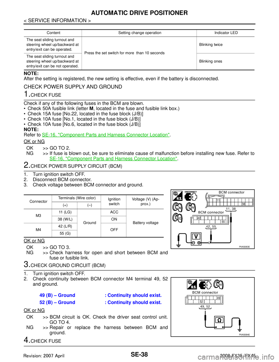
2.CHECK POWER SUPPLY CIRCUIT (BCM)
1. Turn ignition switch OFF.
2. Disconnect BCM connector.
3. Check voltage between BCM connector and ground.
OK or NG
OK >> GO TO 3.
NG >> Check harness for open and short between BCM and fuse or fusible link.
3.CHECK GROUND CIRCUIT (BCM)
1. Turn ignition switch OFF.
2. Check continuity between BCM connector M4 terminal 49, 52 and ground.
OK or NG
OK >> BCM circuit is OK. Check the driver seat control unit. GO TO 4.
NG >> Repair or replace the harness between BCM and ground.
4.CHECK FUSE
Content Setting change operation Indicator LED
The seat sliding turnout and
steering wheel up/backward at
entry/exit can be operated. Press the set switch for more than 10 seconds Blinking twice
The seat sliding turnout and
steering wheel up/backward at
entry/exit can be not operated. Blinking ones
Connector
Terminals (Wire color)
Ignition
switch Voltage (V) (Ap-
prox.)
(+) (–)
M3 11 ( L G )
Ground ACC
Battery voltage
38 (W/L) ON
M4 42 (L/R)
OFF
55 (G)
PIIA5083E
49 (B) – Ground : Continuity should exist.
52 (B) – Ground : Continuity should exist.
PIIA5084E
3AA93ABC3ACD3AC03ACA3AC03AC63AC53A913A773A893A873A873A8E3A773A983AC73AC93AC03AC3
3A893A873A873A8F3A773A9D3AAF3A8A3A8C3A863A9D3AAF3A8B3A8C
Page 3797 of 3924
AWD SYSTEMTF-11
< SERVICE INFORMATION >
CEF
G H
I
J
K L
M A
B
TF
N
O P
AWD SYSTEM
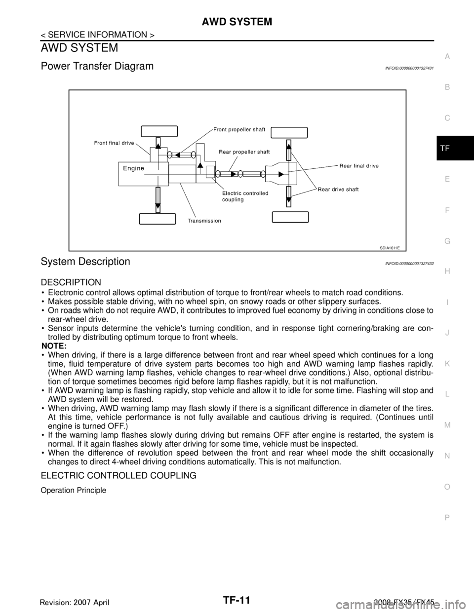
Power Transfer DiagramINFOID:0000000001327431
System DescriptionINFOID:0000000001327432
DESCRIPTION
Electronic control allows optimal distribution of torque to front/rear wheels to match road conditions.
Makes possible stable driving, with no wheel sp in, on snowy roads or other slippery surfaces.
On roads which do not require AWD, it contributes to improved fuel economy by driving in conditions close to
rear-wheel drive.
Sensor inputs determine the vehicle's turning conditi on, and in response tight cornering/braking are con-
trolled by distributing optimum torque to front wheels.
NOTE:
When driving, if there is a large difference between front and rear wheel speed which continues for a long
time, fluid temperature of drive system parts becom es too high and AWD warning lamp flashes rapidly.
(When AWD warning lamp flashes, vehicle changes to r ear-wheel drive conditions.) Also, optional distribu-
tion of torque sometimes becomes rigid before lamp flashes rapidly, but it is not malfunction.
If AWD warning lamp is flashing rapidly, stop vehicle and allow it to idle for some time. Flashing will stop and AWD system will be restored.
When driving, AWD warning lamp may flash slowly if ther e is a significant difference in diameter of the tires.
At this time, vehicle performance is not fully avail able and cautious driving is required. (Continues until
engine is turned OFF.)
If the warning lamp flashes slowly during driving but remains OFF after engine is restarted, the system is
normal. If it again flashes slowly after driving for some time, vehicle must be inspected.
When the difference of revolution speed between the front and rear wheel mode the shift occasionally
changes to direct 4-wheel driving conditions automatically. This is not malfunction.
ELECTRIC CONTROLLED COUPLING
Operation Principle
SDIA1611E
3AA93ABC3ACD3AC03ACA3AC03AC63AC53A913A773A893A873A873A8E3A773A983AC73AC93AC03AC3
3A893A873A873A8F3A773A9D3AAF3A8A3A8C3A863A9D3AAF3A8B3A8C
Page 3798 of 3924
TF-12
< SERVICE INFORMATION >
AWD SYSTEM
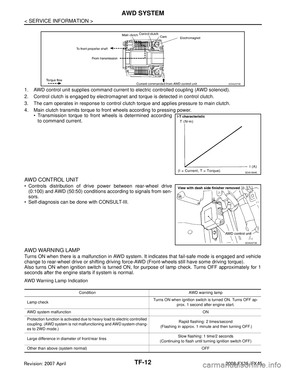
1. AWD control unit supplies command current to electric controlled coupling (AWD solenoid).
2. Control clutch is engaged by electromagnet and torque is detected in control clutch.
3. The cam operates in response to control clutch torque and applies pressure to main clutch.
4. Main clutch transmits torque to front wheels according to pressing power. Transmission torque to front wheels is determined accordingto command current.
AWD CONTROL UNIT
Controls distribution of drive power between rear-wheel drive(0:100) and AWD (50:50) conditions according to signals from sen-
sors.
Self-diagnosis can be done with CONSULT-III.
AWD WARNING LAMP
Turns ON when there is a malfunction in AWD system. It indicates that fail-safe mode is engaged and vehicle
change to rear-wheel drive or shifting driving force- AWD (Front-wheels still have some driving torque).
Also turns ON when ignition switch is turned ON, for purpose of lamp check. Turns OFF approximately for 1
seconds after the engine starts if system is normal.
AWD Warning Lamp Indication
SDIA2270E
SDIA1844E
SDIA2273E
Condition AWD warning lamp
Lamp check Turns ON when ignition switch is turned ON. Turns OFF ap-
prox. 1 second after engine start.
AWD system malfunction ON
Protection function is activated due to heavy load to electric controlled
coupling. (AWD system is not malfunctioning and AWD system chang-
es to 2WD mode.) Rapid flashing: 2 times/second
(Flashing in approx. 1 minute and then turning OFF.)
Large difference in diameter of front/rear tires Slow flashing: 1 time/2 seconds
(Continuing to flash until turning ignition switch OFF)
Other than above (system normal) OFF
3AA93ABC3ACD3AC03ACA3AC03AC63AC53A913A773A893A873A873A8E3A773A983AC73AC93AC03AC3
3A893A873A873A8F3A773A9D3AAF3A8A3A8C3A863A9D3AAF3A8B3A8C
Page 3800 of 3924
TF-14
< SERVICE INFORMATION >
TROUBLE DIAGNOSIS
TROUBLE DIAGNOSIS
Fail-Safe FunctionINFOID:0000000001327435
If any malfunction occurs in AWD electrical system, and control unit detects the malfunction, AWD warning
lamp on combination meter turns ON to indicate system malfunction.
When AWD warning lamp is ON, vehicle changes to rear-wheel drive or shifting driving force-AWD (Front-
wheels still have some driving torque).
How to Perform Trouble DiagnosisINFOID:0000000001327436
BASIC CONCEPT
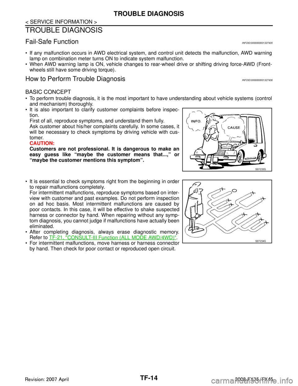
To perform trouble diagnosis, it is the most import ant to have understanding about vehicle systems (control
and mechanism) thoroughly.
It is also important to clarify customer complaints before inspec-
tion.
First of all, reproduce symptoms, and understand them fully.
Ask customer about his/her complaints carefully. In some cases, it
will be necessary to check symptoms by driving vehicle with cus-
tomer.
CAUTION:
Customers are not professional. It is dangerous to make an
easy guess like “maybe the customer means that...,” or
“maybe the customer mentions this symptom”.
It is essential to check symptoms right from the beginning in order to repair malfunctions completely.
For intermittent malfunctions, reproduce symptoms based on inter-
view with customer and past examples. Do not perform inspection
on ad hoc basis. Most intermittent malfunctions are caused by
poor contacts. In this case, it will be effective to shake suspected
harness or connector by hand. When repairing without any symp-
tom diagnosis, you cannot judge if malfunctions have actually been
eliminated.
After completing diagnosis, always erase diagnostic memory. Refer to TF-21, "
CONSULT-III Function (ALL MODE AWD/4WD)".
For intermittent malfunctions, move harness or harness connector by hand. Then check for poor contact or reproduced open circuit.
SEF233G
SEF234G
3AA93ABC3ACD3AC03ACA3AC03AC63AC53A913A773A893A873A873A8E3A773A983AC73AC93AC03AC3
3A893A873A873A8F3A773A9D3AAF3A8A3A8C3A863A9D3AAF3A8B3A8C
Page 3807 of 3924

TROUBLE DIAGNOSISTF-21
< SERVICE INFORMATION >
CEF
G H
I
J
K L
M A
B
TF
N
O P
*: The values are changed by throttle opening and engine speed.
CONSULT-III Function (ALL MODE AWD/4WD)INFOID:0000000001327442
FUNCTION
CONSULT-III can display each diagnostic item using the diagnostic test modes shown following.
FR LH SENSOR [km/h] or [mph] Wheel speed (Front wheel
left)Vehicle stopped 0.00 km/h (0.00 mph)
Vehicle running
CAUTION:
Check air pressure of tire under
standard condition.
Approximately equal to
the indication on speed-
ometer (Inside of
±10%)
RR RH SENSOR [km/h] or [mph] Wheel speed (Rear wheel
right)Vehicle stopped 0.00 km/h (0.00 mph)
Vehicle running
CAUTION:
Check air pressure of tire under
standard condition.
Approximately equal to
the indication on speed-
ometer (Inside of
±10%)
RR LH SENSOR [km/h] or [mph] Wheel speed (Rear wheel left) Vehicle stopped 0.00 km/h (0.00 mph)
Vehicle running
CAUTION:
Check air pressure of tire under
standard condition.Approximately equal to
the indication on speed-
ometer (Inside of
±10%)
BATTERY VOLT [V] Power supply voltage for AWD
control unitIgnition switch: ON Battery voltage
THRTL POS SEN [%] Throttle opening condition When depressing accelerator pedal
(Value rises gradually in response to
throttle position.)0 - 100%
ETS SOLENOID [A] Monitored value of current at
AWD solenoidEngine running
At idle speed
Approx. 0.000A
Engine running
When depressing accelerator ped- al Approx. 0.000 - 2.400A*
STOP LAMP SW [ON/OFF] Condition of brake pedal oper-
ationBrake pedal: Depressed ON
Brake pedal: Released OFF
ENG SPEED SIG [RUN/STOP] Condi tion of engine runningEngine stopped
(Engine speed: Less than 400 rpm)
STOP
Engine running
(Engine speed: 400 rpm or more) RUN
ETS ACTUATOR [ON/OFF] Operating condition of AWD
actuator relay (integrated in
AWD control unit)Engine stopped (Ignition
switch: ON)
OFF
Engine running ON
4WD WARN LAMP [ON/OFF] AWD warning lamp conditionAWD warning lamp: ON ON
AWD warning lamp: OFF OFF
4WD MODE MON [AUTO] Control status of AWD Engine running AUTO
DIS-TIRE MONI [mm] Improper size tire installed
conditionVehicle running with normal size tire
installed
0-4 mm
Vehicle running with improper size
tire installed (Front /rear tire size dif-
ference, wear condition) 4-8 mm, 8- mm
P BRAKE SW [ON/OFF] Condition of parking brake Parking brake operated ON
Parking brake not operated OFF
Monitored item [Unit] Content Condition Display value
3AA93ABC3ACD3AC03ACA3AC03AC63AC53A913A773A893A873A873A8E3A773A983AC73AC93AC03AC3
3A893A873A873A8F3A773A9D3AAF3A8A3A8C3A863A9D3AAF3A8B3A8C
Page 3809 of 3924
TROUBLE DIAGNOSISTF-23
< SERVICE INFORMATION >
CEF
G H
I
J
K L
M A
B
TF
N
O P
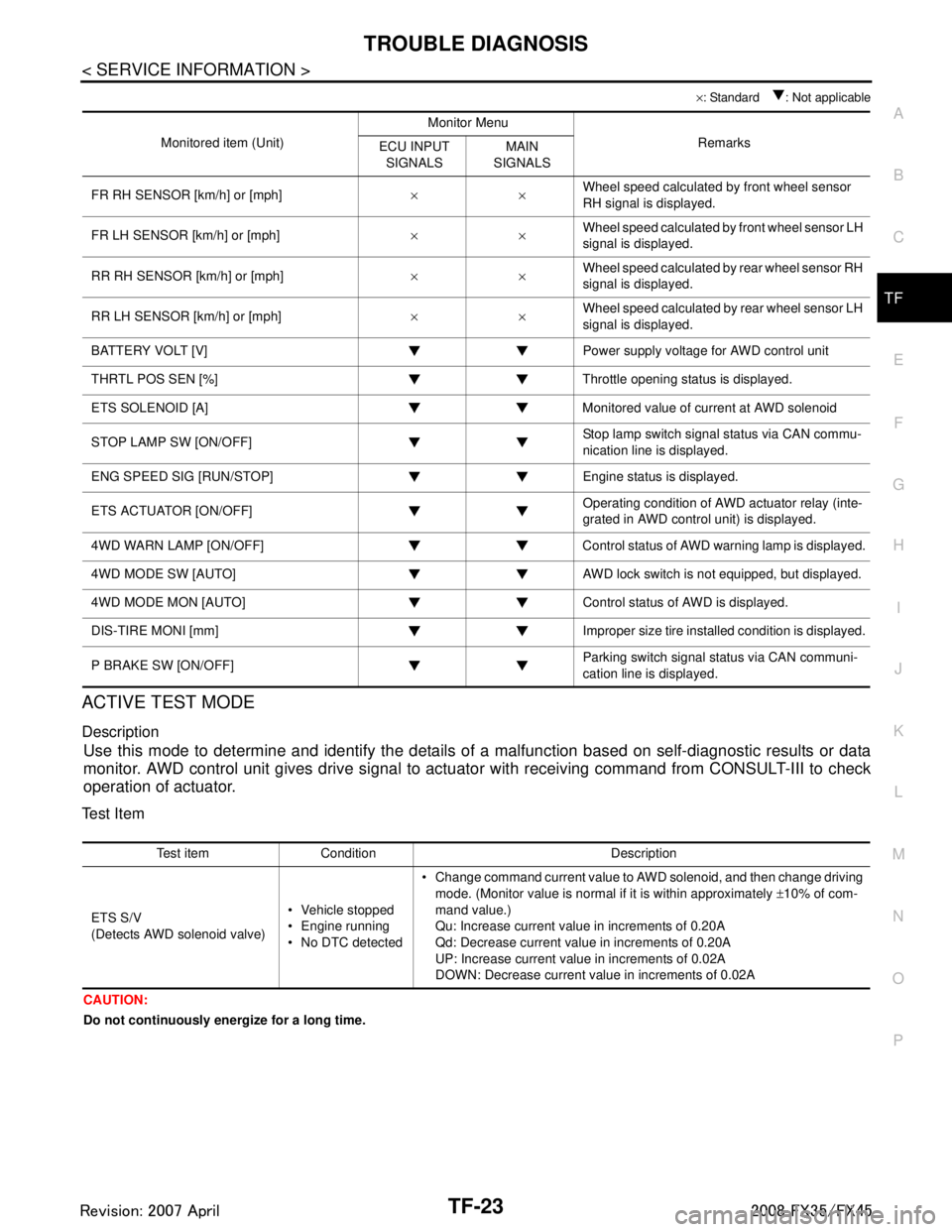
× : Standard : Not applicable
ACTIVE TEST MODE
Description
Use this mode to determine and identify the details of a malfunction based on self-diagnostic results or data
monitor. AWD control unit gives drive signal to actuat or with receiving command from CONSULT-III to check
operation of actuator.
Test Item
CAUTION:
Do not continuously energize for a long time.
Monitored item (Unit) Monitor Menu
Remarks
ECU INPUT
SIGNALS MAIN
SIGNALS
FR RH SENSOR [km/h] or [mph] ××Wheel speed calculated by front wheel sensor
RH signal is displayed.
FR LH SENSOR [km/h] or [mph] ××Wheel speed calculated by front wheel sensor LH
signal is displayed.
RR RH SENSOR [km/h] or [mph] ××Wheel speed calculated by rear wheel sensor RH
signal is displayed.
RR LH SENSOR [km/h] or [mph] ××Wheel speed calculated by rear wheel sensor LH
signal is displayed.
BATTERY VOLT [V] Power supply voltage for AWD control unit
THRTL POS SEN [%] Throttle opening status is displayed.
ETS SOLENOID [A] Monitored value of current at AWD solenoid
STOP LAMP SW [ON/OFF] Stop lamp switch signal status via CAN commu-
nication line is displayed.
ENG SPEED SIG [RUN/STOP] Eng ine status is displayed.
ETS ACTUATOR [ON/OFF] Operating condition of AWD actuator relay (inte-
grated in AWD control unit) is displayed.
4WD WARN LAMP [ON/OFF] Control status of AWD warning lamp is displayed.
4WD MODE SW [AUTO] AWD lock switch is not equipped, but displayed.
4WD MODE MON [AUTO] Control status of AWD is displayed.
DIS-TIRE MONI [mm] Improper size tire installed condition is displayed.
P BRAKE SW [ON/OFF] Parking switch signal status via CAN communi-
cation line is displayed.
Test item Condition Description
ETS S/V
(Detects AWD solenoid valve) Vehicle stopped
Engine running
No DTC detected Change command current value to AWD solenoid, and then change driving
mode. (Monitor value is normal if it is within approximately ±10% of com-
mand value.)
Qu: Increase current value in increments of 0.20A
Qd: Decrease current value in increments of 0.20A
UP: Increase current value in increments of 0.02A
DOWN: Decrease current value in increments of 0.02A
3AA93ABC3ACD3AC03ACA3AC03AC63AC53A913A773A893A873A873A8E3A773A983AC73AC93AC03AC3
3A893A873A873A8F3A773A9D3AAF3A8A3A8C3A863A9D3AAF3A8B3A8C
Page 3862 of 3924
WT-22
< SERVICE INFORMATION >
TROUBLE DIAGNOSES
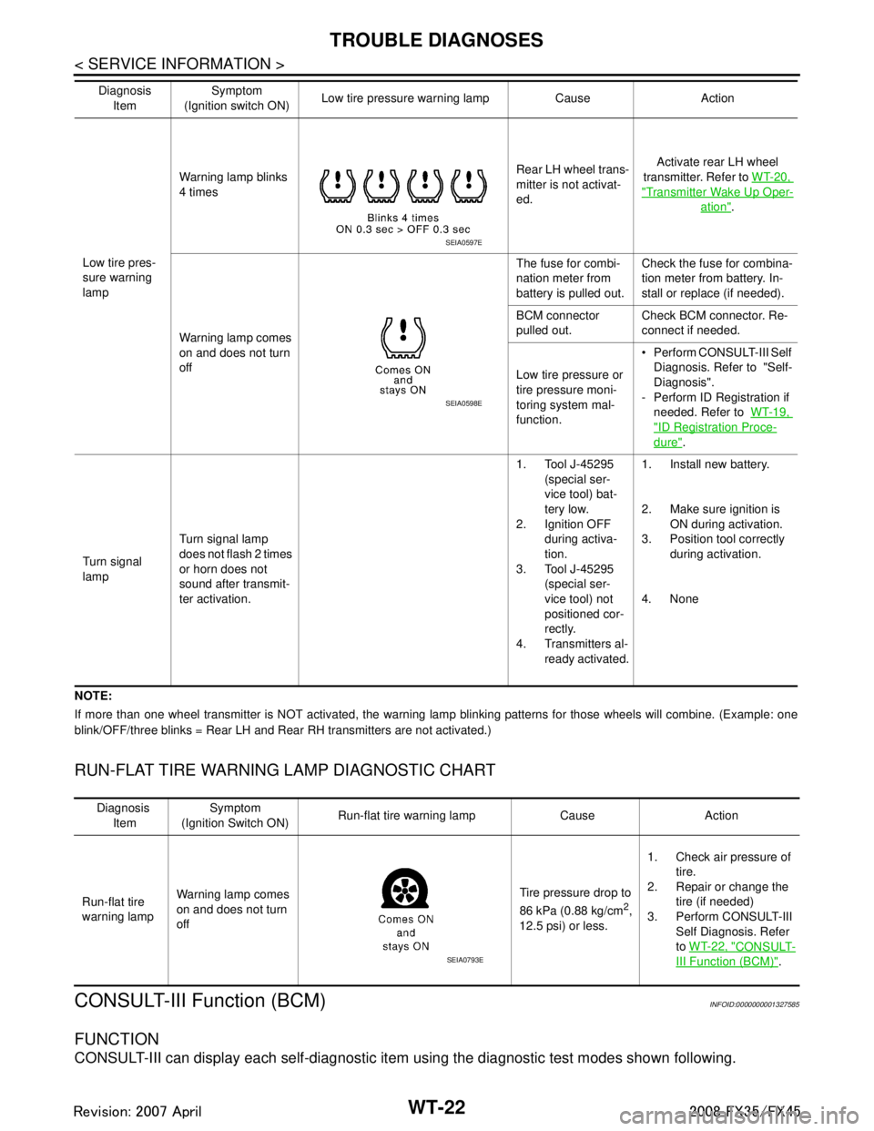
NOTE:
If more than one wheel transmitter is NOT activated, the warning lamp blinking patterns for those wheels will combine. (Example: one
blink/OFF/three blinks = Rear LH and Rear RH transmitters are not activated.)
RUN-FLAT TIRE WARNING LAMP DIAGNOSTIC CHART
CONSULT-III Function (BCM)INFOID:0000000001327585
FUNCTION
CONSULT-III can display each self-diagnostic item using the diagnostic test modes shown following.
Low tire pres-
sure warning
lampWarning lamp blinks
4 times
Rear LH wheel trans-
mitter is not activat-
ed.Activate rear LH wheel
transmitter. Refer to WT-20,
"Transmitter Wake Up Oper-
ation".
Warning lamp comes
on and does not turn
off The fuse for combi-
nation meter from
battery is pulled out.
Check the fuse for combina-
tion meter from battery. In-
stall or replace (if needed).
BCM connector
pulled out. Check BCM connector. Re-
connect if needed.
Low tire pressure or
tire pressure moni-
toring system mal-
function. Perform CONSULT-III Self
Diagnosis. Refer to "Self-
Diagnosis".
- Perform ID Registration if needed. Refer to WT-19,
"ID Registration Proce-
dure".
Turn signal
lamp Turn signal lamp
does not flash 2 times
or horn does not
sound after transmit-
ter activation. 1. Tool J-45295
(special ser-
vice tool) bat-
tery low.
2. Ignition OFF
during activa-
tion.
3. Tool J-45295
(special ser-
vice tool) not
positioned cor-
rectly.
4. Transmitters al- ready activated. 1. Install new battery.
2. Make sure ignition is
ON during activation.
3. Position tool correctly during activation.
4. None
Diagnosis
Item Symptom
(Ignition switch ON) Low tire pressure wa
rning lamp Cause Action
SEIA0597E
SEIA0598E
Diagnosis
Item Symptom
(Ignition Switch ON) Run-flat tire warning lamp Cause Action
Run-flat tire
warning lamp Warning lamp comes
on and does not turn
off Tire pressure drop to
86 kPa (0.88 kg/cm
2,
12.5 psi) or less. 1. Check air pressure of
tire.
2. Repair or change the
tire (if needed)
3. Perform CONSULT-III Self Diagnosis. Refer
to WT-22, "
CONSULT-
III Function (BCM)".SEIA0793E
3AA93ABC3ACD3AC03ACA3AC03AC63AC53A913A773A893A873A873A8E3A773A983AC73AC93AC03AC3
3A893A873A873A8F3A773A9D3AAF3A8A3A8C3A863A9D3AAF3A8B3A8C