Page 2734 of 3924
![INFINITI FX35 2008 Service Manual
EM-250
< SERVICE INFORMATION >[VK45DE]
CYLINDER BLOCK
c. Then tighten all connecting rod nuts 60 degrees clockwise.
(Angle tightening)
CAUTION:
Use angle wrench (SST) to ch eck tightening angle. Do n INFINITI FX35 2008 Service Manual
EM-250
< SERVICE INFORMATION >[VK45DE]
CYLINDER BLOCK
c. Then tighten all connecting rod nuts 60 degrees clockwise.
(Angle tightening)
CAUTION:
Use angle wrench (SST) to ch eck tightening angle. Do n](/manual-img/42/57017/w960_57017-2733.png)
EM-250
< SERVICE INFORMATION >[VK45DE]
CYLINDER BLOCK
c. Then tighten all connecting rod nuts 60 degrees clockwise.
(Angle tightening)
CAUTION:
Use angle wrench (SST) to ch eck tightening angle. Do not
make judgment by visual inspection.
After tightening connecting rod nuts, make sure that crank-
shaft rotates smoothly.
Check the connecting rod side clearance. Refer to EM-256,
"Inspection After Disassembly".
16. Install knock sensor. Install it with its connector facing the rear of engine.
Install the sub-harness with its shorter branch line to the rightbank.
CAUTION:
Do not tighten mounting bolts while holding connector.
If any impact by dropping is applied to knock sensor, replace it with new one.
NOTE:
Make sure that there is no foreign material on the cylinder block mating surface and the bac k surface of knock sensor.
Make sure that knock sensor does not interfere with other parts.
17. Note the following, and assemble in the re verse order of disassembly after this step.
Drive plate When installing drive plate to crankshaft, be sure to correctly
align crankshaft side guide pin and drive plate side guide pin
hole.
- If these are not aligned correctly, engine runs roughly and
“MIL” turns on.
Install drive plate, reinforcement plate and pilot converter (if not installed in step 4) as shown in the figure.
Face chamfered or rounded edge side to crankshaft.
Holding ring gear with ring gear stopper [SST: J-45476].
Tighten mounting bolts crosswise over several times.
When install pilot converter, using drift [outer diameter: approx. 35 mm (1.38 in)]. Press-fit as far as it will go.
CAUTION:
Make sure that guide pin is installed at the rear end of
crankshaft.
How to Select Piston and BearingINFOID:0000000001325805
DESCRIPTION
: 14.7 N·m (1.5 kg-m, 11 ft-lb)
PBIC0104E
PBIC0105E
PBIC0106E
PBIC1965E
3AA93ABC3ACD3AC03ACA3AC03AC63AC53A913A773A893A873A873A8E3A773A983AC73AC93AC03AC3
3A893A873A873A8F3A773A9D3AAF3A8A3A8C3A863A9D3AAF3A8B3A8C
Page 2744 of 3924
![INFINITI FX35 2008 Service Manual
EM-260
< SERVICE INFORMATION >[VK45DE]
CYLINDER BLOCK
If replacing connecting rod assembly, refer to "CONNECTING
ROD BEARING OIL CLEARANCE" to select the connecting rod
bearing.
Factory installed p INFINITI FX35 2008 Service Manual
EM-260
< SERVICE INFORMATION >[VK45DE]
CYLINDER BLOCK
If replacing connecting rod assembly, refer to "CONNECTING
ROD BEARING OIL CLEARANCE" to select the connecting rod
bearing.
Factory installed p](/manual-img/42/57017/w960_57017-2743.png)
EM-260
< SERVICE INFORMATION >[VK45DE]
CYLINDER BLOCK
If replacing connecting rod assembly, refer to "CONNECTING
ROD BEARING OIL CLEARANCE" to select the connecting rod
bearing.
Factory installed parts grading: Service parts apply only to grade “0”.
Unit: mm (in)
*: After installing in connecting rod
CYLINDER BLOCK DISTORTION
Using scraper, remove gasket on the cylinder block surface, and also remove engine oil, scale, carbon, orother contamination.
CAUTION:
Be careful not to allow gasket flakes to en ter engine oil or engine coolant passages.
Measure the distortion on the cylinder block upper face at some different points in six directions with straightedge and feeler gauge.
If it exceeds the limit, replace cylinder block.
MAIN BEARING HOUSING INNER DIAMETER
Install main bearing caps and main bearing without installing main bearings, and tighten main bearing cap bolts to the specified
torque. Refer to EM-242, "
Disassembly and Assembly" for the
tightening procedure.
Measure the inner diameter of main bearing housing with bore gauge.
If out of the standard, replace cylinder block and main bearing caps as assembly.
NOTE:
Cylinder block cannot be replaced as a single part, because it is
machined together with main bearing caps.
PISTON TO CYLINDER BORE CLEARANCE
Cylinder Bore Inner Diameter
PBIC2164E
Grade 0 1
Connecting rod bushing
inner diameter * 22.000 - 22.006
(0.8661 - 0.8664) 22.006 - 22.012
(0.8664 - 0.8666)
Piston pin hole diameter 21.993 - 21.999
(0.8659 - 0.8661) 21.999 - 22.005
(0.8661 - 0.8663)
Piston pin outer diameter 21.989 - 21.995
(0.8657 - 0.8659) 21.995 - 22. 001
(0.8659 - 0.8662)
PBIC2372E
Limit : 0.1 mm (0.004 in)
SEM123C
Standard : 68.944 - 68.968 mm (2.7143 - 2.7153 in)
PBIC1643E
3AA93ABC3ACD3AC03ACA3AC03AC63AC53A913A773A893A873A873A8E3A773A983AC73AC93AC03AC3
3A893A873A873A8F3A773A9D3AAF3A8A3A8C3A863A9D3AAF3A8B3A8C
Page 2761 of 3924
EX-1
ENGINE
C
DE
F
G H
I
J
K L
M
SECTION EX
A
EX
N
O P
CONTENTS
EXHAUST SYSTEM
SERVICE INFORMATION .. ..........................2
PREPARATION .............................................. .....2
Commercial Service Tool .................................... ......2
EXHAUST SYSTEM ...........................................3
Checking Exhaust System ................................... .....3
Component ...............................................................3
Removal and Installation ..........................................4
3AA93ABC3ACD3AC03ACA3AC03AC63AC53A913A773A893A873A873A8E3A773A983AC73AC93AC03AC3
3A893A873A873A8F3A773A9D3AAF3A8A3A8C3A863A9D3AAF3A8B3A8C
Page 2764 of 3924

EX-4
< SERVICE INFORMATION >
EXHAUST SYSTEM
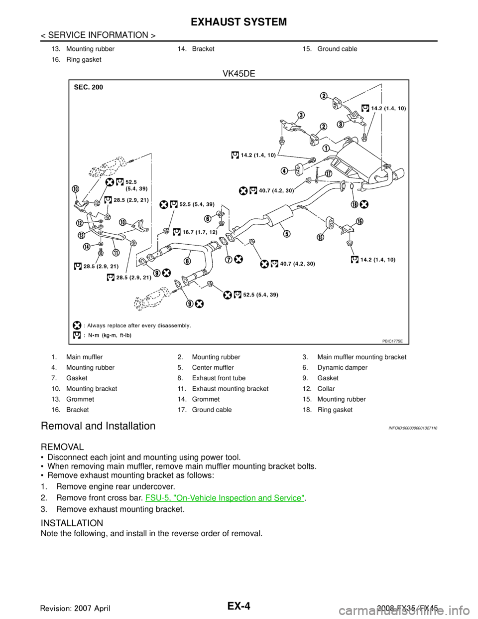
VK45DE
Removal and InstallationINFOID:0000000001327116
REMOVAL
Disconnect each joint and mounting using power tool.
When removing main muffler, remove main muffler mounting bracket bolts.
Remove exhaust mounting bracket as follows:
1. Remove engine rear undercover.
2. Remove front cross bar. FSU-5, "
On-Vehicle Inspection and Service".
3. Remove exhaust mounting bracket.
INSTALLATION
Note the following, and install in the reverse order of removal.
13. Mounting rubber 14. Bracket 15. Ground cable
16. Ring gasket
PBIC1775E
1. Main muffler 2. Mounting rubber 3. Main muffler mounting bracket
4. Mounting rubber 5. Center muffler 6. Dynamic damper
7. Gasket 8. Exhaust front tube 9. Gasket
10. Mounting bracket 11. Exhaust mounting bracket 12. Collar
13. Grommet 14. Grommet 15. Mounting rubber
16. Bracket 17. Ground cable 18. Ring gasket
3AA93ABC3ACD3AC03ACA3AC03AC63AC53A913A773A893A873A873A8E3A773A983AC73AC93AC03AC3
3A893A873A873A8F3A773A9D3AAF3A8A3A8C3A863A9D3AAF3A8B3A8C
Page 2765 of 3924

EXHAUST SYSTEMEX-5
< SERVICE INFORMATION >
C
DE
F
G H
I
J
K L
M A
EX
NP
O
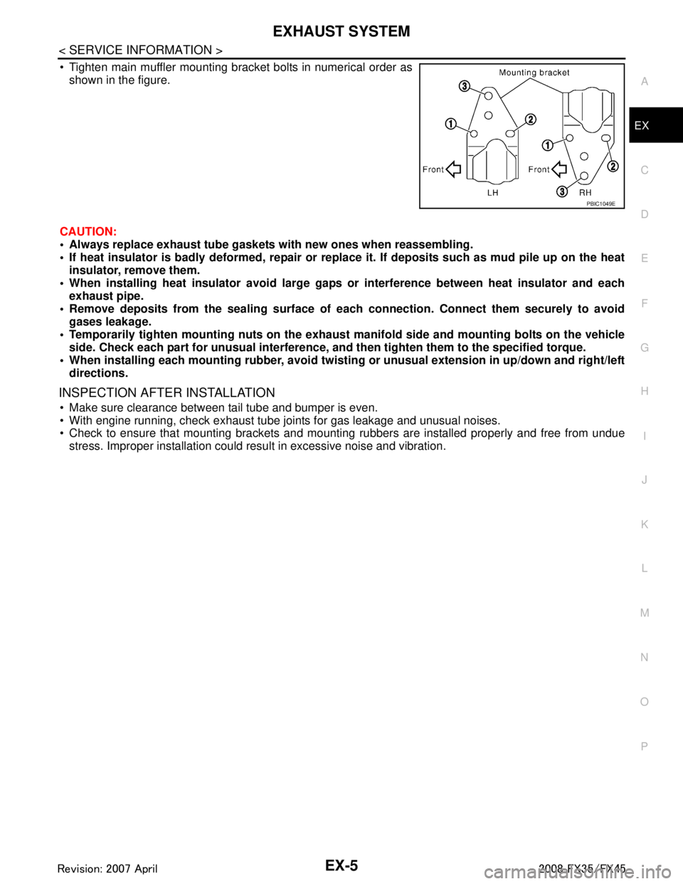
Tighten main muffler mounting bracket bolts in numerical order as
shown in the figure.
CAUTION:
Always replace exhaust tube gasket s with new ones when reassembling.
If heat insulator is badly deformed, repair or repl ace it. If deposits such as mud pile up on the heat
insulator, remove them.
When installing heat insulator avoid large gaps or interference between heat insulator and each
exhaust pipe.
Remove deposits from the sealing surface of each connection. Connect them securely to avoid
gases leakage.
Temporarily tighten mounting nuts on the exhaust manifold side and mounting bolts on the vehicle
side. Check each part for unusual interference, an d then tighten them to the specified torque.
When installing each mounting rubber, avoid twisting or unusual extension in up/down and right/left
directions.
INSPECTION AFTER INSTALLATION
Make sure clearance between tail tube and bumper is even.
With engine running, check exhaust tube joints for gas leakage and unusual noises.
Check to ensure that mounting brackets and mount ing rubbers are installed properly and free from undue
stress. Improper installation could resu lt in excessive noise and vibration.
PBIC1049E
3AA93ABC3ACD3AC03ACA3AC03AC63AC53A913A773A893A873A873A8E3A773A983AC73AC93AC03AC3
3A893A873A873A8F3A773A9D3AAF3A8A3A8C3A863A9D3AAF3A8B3A8C
Page 2791 of 3924
FAX-26
< SERVICE INFORMATION >[AWD]
SERVICE DATA AND SPECIFICATIONS (SDS)
SERVICE DATA AND SPECIFICATIONS (SDS)
Wheel BearingINFOID:0000000001327520
Drive ShaftINFOID:0000000001327521
Axial end play
0.05 mm (0.002 in) or less
Joint Wheel side Front final drive assembly side
Engine type VQ35DE models VK45DE models VQ35DE models VK45DE models
Grease quantityLH side
77 – 97 g (2.71 – 3.42 oz) 95 – 105 g (3.35 – 3.70 oz)
RH side 113 – 123 g (3.98 – 4.33 oz)
Boots installed length LH side
136 mm (5.35 in) 150.9 – 152.9 mm (5.94
– 6.02 in) 95 – 97 mm
(3.74 – 3.82 in)
RH side 157.55 – 159.55 mm (6.20 – 6.28 in)
3AA93ABC3ACD3AC03ACA3AC03AC63AC53A913A773A893A873A873A8E3A773A983AC73AC93AC03AC3
3A893A873A873A8F3A773A9D3AAF3A8A3A8C3A863A9D3AAF3A8B3A8C
Page 2799 of 3924

FFD-8
< SERVICE INFORMATION >
DIFFERENTIAL GEAR OIL
DIFFERENTIAL GEAR OIL
Changing Differential Gear OilINFOID:0000000001327481
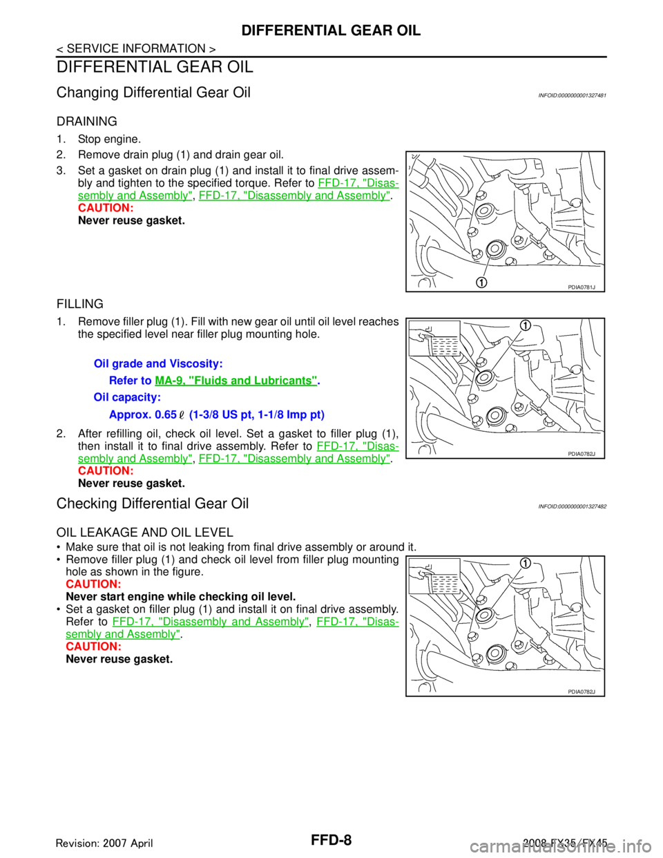
DRAINING
1. Stop engine.
2. Remove drain plug (1) and drain gear oil.
3. Set a gasket on drain plug (1) and install it to final drive assem-bly and tighten to the specified torque. Refer to FFD-17, "
Disas-
sembly and Assembly", FFD-17, "Disassembly and Assembly".
CAUTION:
Never reuse gasket.
FILLING
1. Remove filler plug (1). Fill with new gear oil until oil level reaches the specified level near filler plug mounting hole.
2. After refilling oil, check oil level. Set a gasket to filler plug (1), then install it to final drive assembly. Refer to FFD-17, "
Disas-
sembly and Assembly", FFD-17, "Disassembly and Assembly".
CAUTION:
Never reuse gasket.
Checking Differential Gear OilINFOID:0000000001327482
OIL LEAKAGE AND OIL LEVEL
Make sure that oil is not leaking fr om final drive assembly or around it.
Remove filler plug (1) and check oil level from filler plug mounting hole as shown in the figure.
CAUTION:
Never start engine while checking oil level.
Set a gasket on filler plug (1) and install it on final drive assembly.
Refer to FFD-17, "
Disassembly and Assembly", FFD-17, "Disas-
sembly and Assembly".
CAUTION:
Never reuse gasket.
PDIA0781J
Oil grade and Viscosity:
Refer to MA-9, "
Fluids and Lubricants".
Oil capacity:
Approx. 0.65 (1-3/8 US pt, 1-1/8 Imp pt)
PDIA0782J
PDIA0782J
3AA93ABC3ACD3AC03ACA3AC03AC63AC53A913A773A893A873A873A8E3A773A983AC73AC93AC03AC3
3A893A873A873A8F3A773A9D3AAF3A8A3A8C3A863A9D3AAF3A8B3A8C
Page 2803 of 3924

FFD-12
< SERVICE INFORMATION >
SIDE OIL SEAL
SIDE OIL SEAL
Removal and InstallationINFOID:0000000001327484
NOTE:
Left side oil seal is attached to engine assembly. Replace it when front final drive assembly is removed
from vehicle.
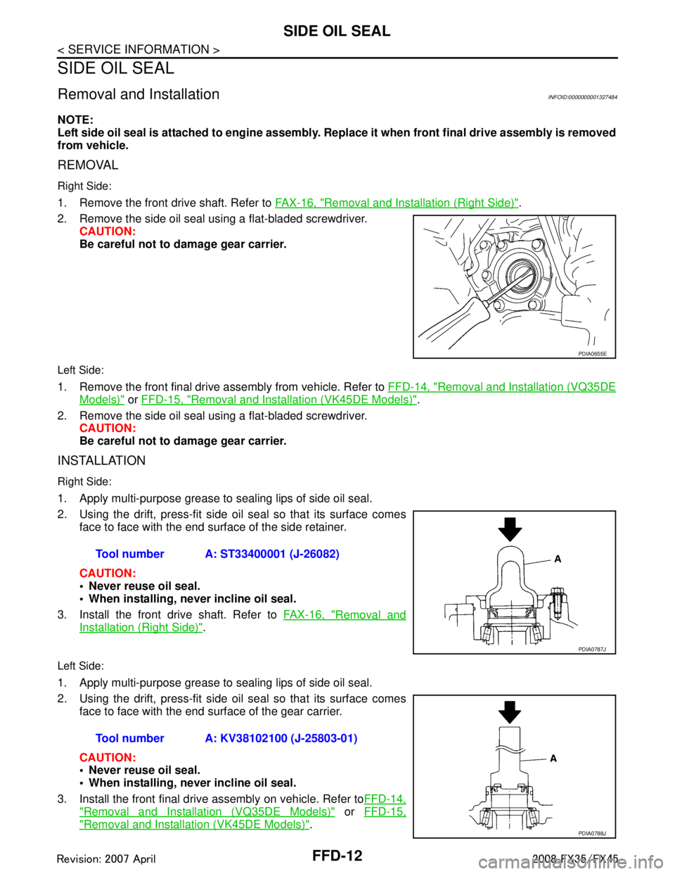
REMOVAL
Right Side:
1. Remove the front drive shaft. Refer to FAX-16, "Removal and Installation (Right Side)".
2. Remove the side oil seal using a flat-bladed screwdriver. CAUTION:
Be careful not to damage gear carrier.
Left Side:
1. Remove the front final drive assembly from vehicle. Refer to FFD-14, "Removal and Installation (VQ35DE
Models)" or FFD-15, "Removal and Installation (VK45DE Models)".
2. Remove the side oil seal using a flat-bladed screwdriver. CAUTION:
Be careful not to damage gear carrier.
INSTALLATION
Right Side:
1. Apply multi-purpose grease to sealing lips of side oil seal.
2. Using the drift, press-fit side oil seal so that its surface comesface to face with the end surface of the side retainer.
CAUTION:
Never reuse oil seal.
When installing, n ever incline oil seal.
3. Install the front drive shaft. Refer to FAX-16, "
Removal and
Installation (Right Side)".
Left Side:
1. Apply multi-purpose grease to sealing lips of side oil seal.
2. Using the drift, press-fit side oil seal so that its surface comes
face to face with the end surface of the gear carrier.
CAUTION:
Never reuse oil seal.
When installing, n ever incline oil seal.
3. Install the front final drive assembly on vehicle. Refer to FFD-14,
"Removal and Installation (VQ35DE Models)" or FFD-15,
"Removal and Installation (VK45DE Models)".
PDIA0655E
Tool number A: ST33400001 (J-26082)
PDIA0787J
Tool number A: KV38102100 (J-25803-01)
PDIA0788J
3AA93ABC3ACD3AC03ACA3AC03AC63AC53A913A773A893A873A873A8E3A773A983AC73AC93AC03AC3
3A893A873A873A8F3A773A9D3AAF3A8A3A8C3A863A9D3AAF3A8B3A8C