2008 INFINITI FX35 oil change
[x] Cancel search: oil changePage 2604 of 3924
![INFINITI FX35 2008 Service Manual
EM-120
< SERVICE INFORMATION >[VQ35DE]
ENGINE ASSEMBLY
CAUTION:
Confirm there is no interference with the vehicle.
Make sure that all connection
points have been disconnected.
Keep in mind the INFINITI FX35 2008 Service Manual
EM-120
< SERVICE INFORMATION >[VQ35DE]
ENGINE ASSEMBLY
CAUTION:
Confirm there is no interference with the vehicle.
Make sure that all connection
points have been disconnected.
Keep in mind the](/manual-img/42/57017/w960_57017-2603.png)
EM-120
< SERVICE INFORMATION >[VQ35DE]
ENGINE ASSEMBLY
CAUTION:
Confirm there is no interference with the vehicle.
Make sure that all connection
points have been disconnected.
Keep in mind the center of the vehicle gravity changes. If necessary, use jack(s) to support the
vehicle at rear jacking point(s) to pr event it from falling it off the lift.
Separation Work
1. Install engine slingers into front of cylinder head (right bank) and
rear of cylinder head (left bank).
To protect rocker cover against damage caused by tilting ofengine slinger, insert spacer between cylinder head and
engine rear lower slinger, in direction shown in the figure.
NOTE:
Spacer is a component part of engine rear upper slinger
assembly.
2. Remove power steering oil pump from engine side. Refer to PS-27, "
On-Vehicle Inspection and Service".
3. Remove engine mounting insulators (RH and LH) under side nuts with power tool.
4. Lift with hoist and separate the engine, the transmi ssion assembly, the transfer assembly and the front
final drive assembly from front suspension member.
CAUTION:
Before and during this lifting, always check if any harnesses are left connected.
Avoid damage to and oil/grease smearing or spills onto engine mounting insulator.
5. Remove alternator. Refer to SC-19, "
System Description".
6. Remove starter motor. Refer to SC-8
.
7. Remove front propeller shaft from the front final drive assembly side. Refer to PR-4, "
On-Vehicle Inspec-
tion".
8. Separate the engine from the transmission assembly. Refer to AT-241, "
Removal and Installation (2WD
Models)".
9. Remove the front final drive assembly from oil pan (upper). Refer to FFD-14, "
Removal and Installation
(VQ35DE Models)".
10. Remove each engine mounting insulator and each engine mounting bracket from the engine with power
tool.
11. Remove rear engine mounting member and engine m ounting insulator (rear) from the transmission
assembly.
12. Remove dynamic damper from the transfer assembly.
INSTALLATION
Note the following, and install in the reverse order of removal.
Do not allow engine mounting insulator to be damage and careful no engine oil gets on it.
For a location with a positioning pin, insert it securely into hole of mating part.
For a part with a specified installation orientation, refer to component figure in EM-117, "
Component (AWD
Models)".
Slinger bolts:
: 28.0 N·m (2.9 kg-m, 21 ft-lb)
PBIC2061E
KBIA1017E
3AA93ABC3ACD3AC03ACA3AC03AC63AC53A913A773A893A873A873A8E3A773A983AC73AC93AC03AC3
3A893A873A873A8F3A773A9D3AAF3A8A3A8C3A863A9D3AAF3A8B3A8C
Page 2690 of 3924
![INFINITI FX35 2008 Service Manual
EM-206
< SERVICE INFORMATION >[VK45DE]
TIMING CHAIN
4. Install timing chains and related parts.
Align the mating mark on each sprocket and timing chain for installation.NOTE:
Before installing chai INFINITI FX35 2008 Service Manual
EM-206
< SERVICE INFORMATION >[VK45DE]
TIMING CHAIN
4. Install timing chains and related parts.
Align the mating mark on each sprocket and timing chain for installation.NOTE:
Before installing chai](/manual-img/42/57017/w960_57017-2689.png)
EM-206
< SERVICE INFORMATION >[VK45DE]
TIMING CHAIN
4. Install timing chains and related parts.
Align the mating mark on each sprocket and timing chain for installation.NOTE:
Before installing chain tensioner, it is possible to change the position of mating mark on timing chain for
that on each sprocket for alignment.
CAUTION:
For the above reason, after the mating marks ar e aligned, keep them aligned by holding them
with a hand.
Install slack guides and tension guides onto correct si de by checking with identification mark on surface.
Install chain tensioner with plunger fixed as described in its removal.
CAUTION:
Before and after the installation of chain tens ioner, make sure that the mating mark on timing
chain is not out of alignment.
After installing chain tensioner, remove stoppe r pin to release tensioner. Make sure tensioner
is released.
To avoid chain-link skipping of timing chain, do not move crankshaft or camshafts until front
cover is installed.
5. Perform the same procedure as for right bank, install timing chain and related parts on left side.
6. Install oil pump. Refer to LU-29
.
7. Install oil pump drive spacer as follows:
a. Insert oil pump drive spacer according to the directions of crank- shaft key and the two flat surfaces of oil pump inner rotor.
If the positional relationship does not allow the insertion, rotate
oil pump inner rotor with a finger to allow spacer.
b. After confirming that the position of each part is in correct condi- tion to allow for spacer, force fit spacer by lightly tapping with
plastic hammer until it contacts and does not go further.
8. Install front oil seal on front cover. Apply new engine oil to both oil seal lip and dust seal lip.
PBIC2344E
PBIC0058E
3AA93ABC3ACD3AC03ACA3AC03AC63AC53A913A773A893A873A873A8E3A773A983AC73AC93AC03AC3
3A893A873A873A8F3A773A9D3AAF3A8A3A8C3A863A9D3AAF3A8B3A8C
Page 2702 of 3924
![INFINITI FX35 2008 Service Manual
EM-218
< SERVICE INFORMATION >[VK45DE]
CAMSHAFT
a. Release fuel pressure. Refer to
EC-665, "Fuel Pressure Check".
b. Disconnect ignition coil and injector harness connectors.
3. Remove intake valve INFINITI FX35 2008 Service Manual
EM-218
< SERVICE INFORMATION >[VK45DE]
CAMSHAFT
a. Release fuel pressure. Refer to
EC-665, "Fuel Pressure Check".
b. Disconnect ignition coil and injector harness connectors.
3. Remove intake valve](/manual-img/42/57017/w960_57017-2701.png)
EM-218
< SERVICE INFORMATION >[VK45DE]
CAMSHAFT
a. Release fuel pressure. Refer to
EC-665, "Fuel Pressure Check".
b. Disconnect ignition coil and injector harness connectors.
3. Remove intake valve timing control solenoid valve. Refer to EM-199, "
Component".
4. Crank the engine, and then make sure that engine oil comes out from intake valve timing control cover oil hole. End crank after
checking.
WARNING:
Be careful not to touch rotati ng parts (drive belt, idler pul-
ley, and crankshaft pulley, etc.).
CAUTION:
Engine oil may squirt from intake valve timing control sole-
noid valve installation hole during cranking. Use a shop
cloth to prevent the engine co mponents and the vehicle. Do
not allow engine oil to get on rubber components such as
drive belt or engine mount insulators. Immediately wipe off
any splashed engine oil.
Clean oil groove between oil strainer and intake valve timing control solenoid valve if engine oil does not come out from intake valve timing control cover oil hole. Refer to LU-21, "
Lubrication Circuit".
5. Remove components between intake valve timing c ontrol solenoid valve and camshaft sprocket (INT),
and then check each oil groove for clogging.
Clean oil groove if necessary. Refer to LU-21, "
Lubrication Circuit".
6. After inspection, install removed parts.
Valve ClearanceINFOID:0000000001325792
INSPECTION
In cases of removing/installing or replacing camshaft and valve-related parts, or of unusual engine conditions
due to changes in valve clearance (found malfunctions dur ing starting, idling or causing noise), perform
inspection as follows:
1. Remove rocker covers (right and left bank). Refer to EM-196, "
Component".
2. Measure the valve clearance as follows:
a. Set No. 1 cylinder at TDC of its compression stroke. Rotate crankshaft pulley in clockwise to align TDC identifica-
tion notch (without paint mark) with timing indicator on front
cover.
Make sure that both intake and exhaust cam noses of No. 1 cylinder (engine front side of left bank) are located as shown in
the figure.
If not, turn crankshaft one revolution (360 degrees) and align
as shown in the figure.
PBIC2848E
PBIC2341E
KBIA0400J
3AA93ABC3ACD3AC03ACA3AC03AC63AC53A913A773A893A873A873A8E3A773A983AC73AC93AC03AC3
3A893A873A873A8F3A773A9D3AAF3A8A3A8C3A863A9D3AAF3A8B3A8C
Page 2710 of 3924
![INFINITI FX35 2008 Service Manual
EM-226
< SERVICE INFORMATION >[VK45DE]
CYLINDER HEAD
CYLINDER HEAD
On-Vehicle ServiceINFOID:0000000001325796
CHECKING COMPRESSION PRESSURE
1. Warm up engine thoroughly. Then, stop it.
2. Release fuel INFINITI FX35 2008 Service Manual
EM-226
< SERVICE INFORMATION >[VK45DE]
CYLINDER HEAD
CYLINDER HEAD
On-Vehicle ServiceINFOID:0000000001325796
CHECKING COMPRESSION PRESSURE
1. Warm up engine thoroughly. Then, stop it.
2. Release fuel](/manual-img/42/57017/w960_57017-2709.png)
EM-226
< SERVICE INFORMATION >[VK45DE]
CYLINDER HEAD
CYLINDER HEAD
On-Vehicle ServiceINFOID:0000000001325796
CHECKING COMPRESSION PRESSURE
1. Warm up engine thoroughly. Then, stop it.
2. Release fuel pressure. Refer to
EC-665, "
Fuel Pressure Check".
a. Remove fuel pump fuse to avoid fuel injection during measure- ment.
3. Remove engine cover with power tool. Refer to EM-169, "
Component".
4. Remove ignition coil and spark plug from each cylinder. Refer to EM-187, "
Component" and EM-188,
"Component".
5. Connect engine tachometer (not required in use of CONSULT-III).
6. Install compression gauge with adapter (SST or commercial ser- vice tool) onto spark plug hole.
Use compression gauge adapter (SST) which is required onNo. 7 and 8 cylinders.
Use compression gauge adapter (if no SST is used) whose picking up end inserted to spark plug hole is smaller than 20
mm (0.79 in) in diameter. Otherwise, it may be caught by cylin-
der head during removal.
7. With accelerator pedal fully depressed, turn ignition switch to “START” for cranking. When the gauge pointer stabilizes, read the compression pressure and engine rpm. Perform these steps to check each cyl-
inder.
Compression pressure:
Unit: kPa (kg/cm2, psi)/rpm
CAUTION:
Always use a fully changed battery to obtain the specified engine speed.
PBIB1482E
PBIC1554E
SBIA0533E
Standard Minimum Deferential limit between cylinders
1,320 (13.5, 191)/300 1,130 (11.5, 164)/300 98 (1.0, 14)/300
3AA93ABC3ACD3AC03ACA3AC03AC63AC53A913A773A893A873A873A8E3A773A983AC73AC93AC03AC3
3A893A873A873A8F3A773A9D3AAF3A8A3A8C3A863A9D3AAF3A8B3A8C
Page 2815 of 3924

FFD-24
< SERVICE INFORMATION >
FRONT FINAL DRIVE ASSEMBLY
b. If the runout value is still outside of the limit after the phase has been changed, possible cause will be an
assembly malfunction of drive pinion and pinion bearing and malfunction of pinion bearing. Check for
these items and repair if necessary.
c. If the runout value is still outside of the limit after the check and repair, replace companion flange.
DISASSEMBLY
Side Shaft Assembly
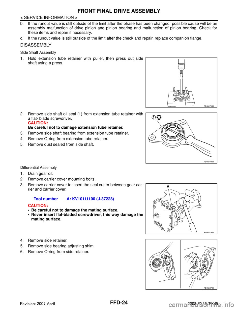
1. Hold extension tube retainer with puller, then press out side shaft using a press.
2. Remove side shaft oil seal (1) from extension tube retainer with a flat- blade screwdriver.
CAUTION:
Be careful not to damage extension tube retainer.
3. Remove side shaft bearing from extension tube retainer.
4. Remove O-ring from extension tube retainer.
5. Remove dust sealed from side shaft.
Differential Assembly
1. Drain gear oil.
2. Remove carrier cover mounting bolts.
3. Remove carrier cover to insert the seal cutter between gear car- rier and carrier cover.
CAUTION:
Be careful not to damage the mating surface.
Never insert flat-bladed screwdriver, this way damage the
mating surface.
4. Remove side retainer.
5. Remove side bearing adjusting shim.
6. Remove O-ring from side retainer.
PDIA0793J
PDIA0794J
Tool number A: KV10111100 (J-37228)
PDIA0795J
PDIA0670E
3AA93ABC3ACD3AC03ACA3AC03AC63AC53A913A773A893A873A873A8E3A773A983AC73AC93AC03AC3
3A893A873A873A8F3A773A9D3AAF3A8A3A8C3A863A9D3AAF3A8B3A8C
Page 2894 of 3924

GI-32
< SERVICE INFORMATION >
SERVICE INFORMATION FOR ELECTRICAL INCIDENT
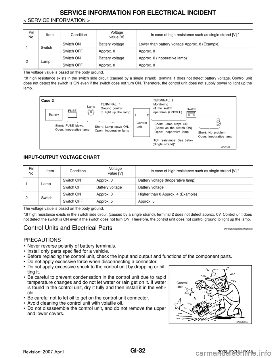
The voltage value is based on the body ground.
*:If high resistance exists in the switch side circuit (caused by a single strand), terminal 1 does not detect battery voltage. Control unit
does not detect the switch is ON even if the switch does not turn ON. Therefore, the control unit does not supply power to ligh t up the
lamp.
INPUT-OUTPUT VOLTAGE CHART
The voltage value is based on the body ground.
*:If high resistance exists in the switch side circuit (caused by a single strand), terminal 2 does not detect approx. 0V. Cont rol unit does
not detect the switch is ON even if the switch does not turn ON. Therefore, the control unit does not control ground to light u p the lamp.
Control Units and Electrical PartsINFOID:0000000001325673
PRECAUTIONS
Never reverse polarity of battery terminals.
Install only parts specified for a vehicle.
Before replacing the control unit, check the input and output and functions of the component parts.
Do not apply excessive force when disconnecting a connector.
Do not apply excessive shock to the control unit by dropping or hit- ting it.
Be careful to prevent condensation in the control unit due to rapid temperature changes and do not let water or rain get on it. If water
is found in the control unit, dry it fully and then install it in the vehi-
cle.
Be careful not to let oil to get on the control unit connector.
Avoid cleaning the control unit with volatile oil.
Do not disassemble the control unit, and do not remove the upper and lower covers.
Pin
No. Item Condition
Vo l ta g e
value [V] In case of high resistance such as single strand [V] *
1Switch Switch ON Battery voltage Lower than battery voltage Approx. 8 (Example)
Switch OFF Approx. 0 Approx. 0
2Lamp Switch ON Battery voltage App
rox. 0 (Inoperative lamp)
Switch OFF Approx. 0 Approx. 0
MGI035A
Pin
No. Item Condition
Vo l ta g e
value [V] In case of high resistance such as single strand [V] *
1Lamp Switch ON Approx. 0 Battery voltage (Inoperative lamp)
Switch OFF Battery voltage Battery voltage
2Switch Switch ON Approx. 0 Higher than 0 Approx. 4 (Example)
Switch OFF Approx. 5 Approx. 5
SAIA0255E
3AA93ABC3ACD3AC03ACA3AC03AC63AC53A913A773A893A873A873A8E3A773A983AC73AC93AC03AC3
3A893A873A873A8F3A773A9D3AAF3A8A3A8C3A863A9D3AAF3A8B3A8C
Page 3070 of 3924
![INFINITI FX35 2008 Service Manual
LAN-50
< SERVICE INFORMATION >[CAN]
TROUBLE DIAGNOSIS
High beam request signal T R R
Horn chirp signal T R
Ignition switch signal T R R
Key fob door unlock signal T R
Key fob ID signal T R
Key switch INFINITI FX35 2008 Service Manual
LAN-50
< SERVICE INFORMATION >[CAN]
TROUBLE DIAGNOSIS
High beam request signal T R R
Horn chirp signal T R
Ignition switch signal T R R
Key fob door unlock signal T R
Key fob ID signal T R
Key switch](/manual-img/42/57017/w960_57017-3069.png)
LAN-50
< SERVICE INFORMATION >[CAN]
TROUBLE DIAGNOSIS
High beam request signal T R R
Horn chirp signal T R
Ignition switch signal T R R
Key fob door unlock signal T R
Key fob ID signal T R
Key switch signal T R
Low beam request signal T R
Oil pressure switch signalRT
TR
Position light request signal R T R R
Rear window defogger switch signal T R
Run flat tire warning lamp signal T R
Sleep wake up signal TRRR
RT
Theft warning horn request signal T R
Tire pressure warning lamp signal T R
Turn indicator signal T R
Alarm request signal R T
Back door open request signal R T
Door lock/unlock request signal R T
Ignition knob switch signal R T
Key warning signal T R
Power window open request signal R T
Steering angle sensor signal T R
Snow mode switch signal R T
Turn LED burnout status signal R T
Distance to empty signal R T
Fuel level low warning signal R T
Fuel level sensor signal R T
Manual mode shift down signal R T
Manual mode shift up signal R T
Manual mode signal R T
Not manual mode signal R T
Parking brake switch signal R R T
Stop lamp switch signal R R T
Vehicle speed signal RRT
R RRRR T R
A/T shift schedule change demand signal R T
ABS operation signal T
ABS warning lamp signal RT
Brake warning lamp signal RT
SLIP indicator lamp signal RT
TCS operation signal T
Signal name/Connecting unit
ECM
4WD
DISP TCM
BCM
I-KEY
STRG M&AABS
ADP
IPDM-E
3AA93ABC3ACD3AC03ACA3AC03AC63AC53A913A773A893A873A873A8E3A773A983AC73AC93AC03AC3
3A893A873A873A8F3A773A9D3AAF3A8A3A8C3A863A9D3AAF3A8B3A8C
Page 3107 of 3924

HEADLAMP - XENON TYPE -LT-5
< SERVICE INFORMATION >
C
DE
F
G H
I
J
L
M A
B
LT
N
O P
HEADLAMP - XENON TYPE -
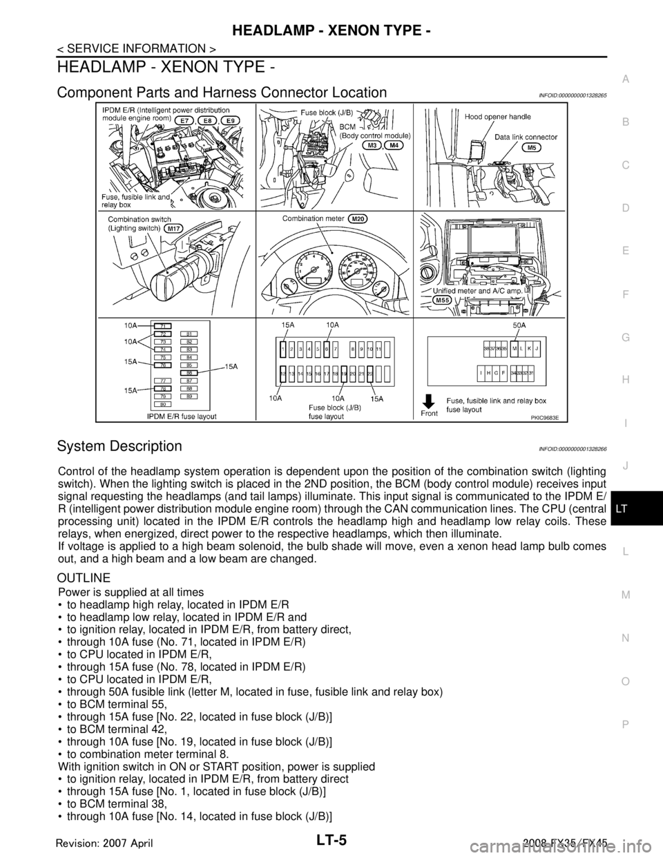
Component Parts and Har ness Connector LocationINFOID:0000000001328265
System DescriptionINFOID:0000000001328266
Control of the headlamp system operation is dependent upon t he position of the combination switch (lighting
switch). When the lighting switch is placed in the 2ND position, the BCM (body control module) receives input
signal requesting the headlamps (and tail lamps) illuminate. This input signal is communicated to the IPDM E/
R (intelligent power distribution module engine room) through the CAN communication lines. The CPU (central
processing unit) located in the IPDM E/R contro ls the headlamp high and headlamp low relay coils. These
relays, when energized, direct power to the respective headlamps, which then illuminate.
If voltage is applied to a high beam solenoid, the bulb shade will move, even a xenon head lamp bulb comes
out, and a high beam and a low beam are changed.
OUTLINE
Power is supplied at all times
to headlamp high relay, located in IPDM E/R
to headlamp low relay, located in IPDM E/R and
to ignition relay, located in IPDM E/R, from battery direct,
through 10A fuse (No. 71, located in IPDM E/R)
to CPU located in IPDM E/R,
through 15A fuse (No. 78, located in IPDM E/R)
to CPU located in IPDM E/R,
through 50A fusible link (letter M, located in fuse, fusible link and relay box)
to BCM terminal 55,
through 15A fuse [No. 22, located in fuse block (J/B)]
to BCM terminal 42,
through 10A fuse [No. 19, located in fuse block (J/B)]
to combination meter terminal 8.
With ignition switch in ON or START position, power is supplied
to ignition relay, located in IPDM E/R, from battery direct
through 15A fuse [No. 1, located in fuse block (J/B)]
to BCM terminal 38,
through 10A fuse [No. 14, located in fuse block (J/B)]
PKIC9683E
3AA93ABC3ACD3AC03ACA3AC03AC63AC53A913A773A893A873A873A8E3A773A983AC73AC93AC03AC3
3A893A873A873A8F3A773A9D3AAF3A8A3A8C3A863A9D3AAF3A8B3A8C