Page 3110 of 3924
LT-8
< SERVICE INFORMATION >
HEADLAMP - XENON TYPE -
Schematic
INFOID:0000000001328269
TKWM4289E
3AA93ABC3ACD3AC03ACA3AC03AC63AC53A913A773A893A873A873A8E3A773A983AC73AC93AC03AC3
3A893A873A873A8F3A773A9D3AAF3A8A3A8C3A863A9D3AAF3A8B3A8C
Page 3111 of 3924
HEADLAMP - XENON TYPE -LT-9
< SERVICE INFORMATION >
C
DE
F
G H
I
J
L
M A
B
LT
N
O P
Wiring Diagram - H/LAMP -INFOID:0000000001328270
TKWM4290E
3AA93ABC3ACD3AC03ACA3AC03AC63AC53A913A773A893A873A873A8E3A773A983AC73AC93AC03AC3
3A893A873A873A8F3A773A9D3AAF3A8A3A8C3A863A9D3AAF3A8B3A8C
Page 3112 of 3924
LT-10
< SERVICE INFORMATION >
HEADLAMP - XENON TYPE -
TKWM4291E
3AA93ABC3ACD3AC03ACA3AC03AC63AC53A913A773A893A873A873A8E3A773A983AC73AC93AC03AC3
3A893A873A873A8F3A773A9D3AAF3A8A3A8C3A863A9D3AAF3A8B3A8C
Page 3113 of 3924
HEADLAMP - XENON TYPE -LT-11
< SERVICE INFORMATION >
C
DE
F
G H
I
J
L
M A
B
LT
N
O P
TKWM0604E
3AA93ABC3ACD3AC03ACA3AC03AC63AC53A913A773A893A873A873A8E3A773A983AC73AC93AC03AC3
3A893A873A873A8F3A773A9D3AAF3A8A3A8C3A863A9D3AAF3A8B3A8C
Page 3114 of 3924
LT-12
< SERVICE INFORMATION >
HEADLAMP - XENON TYPE -
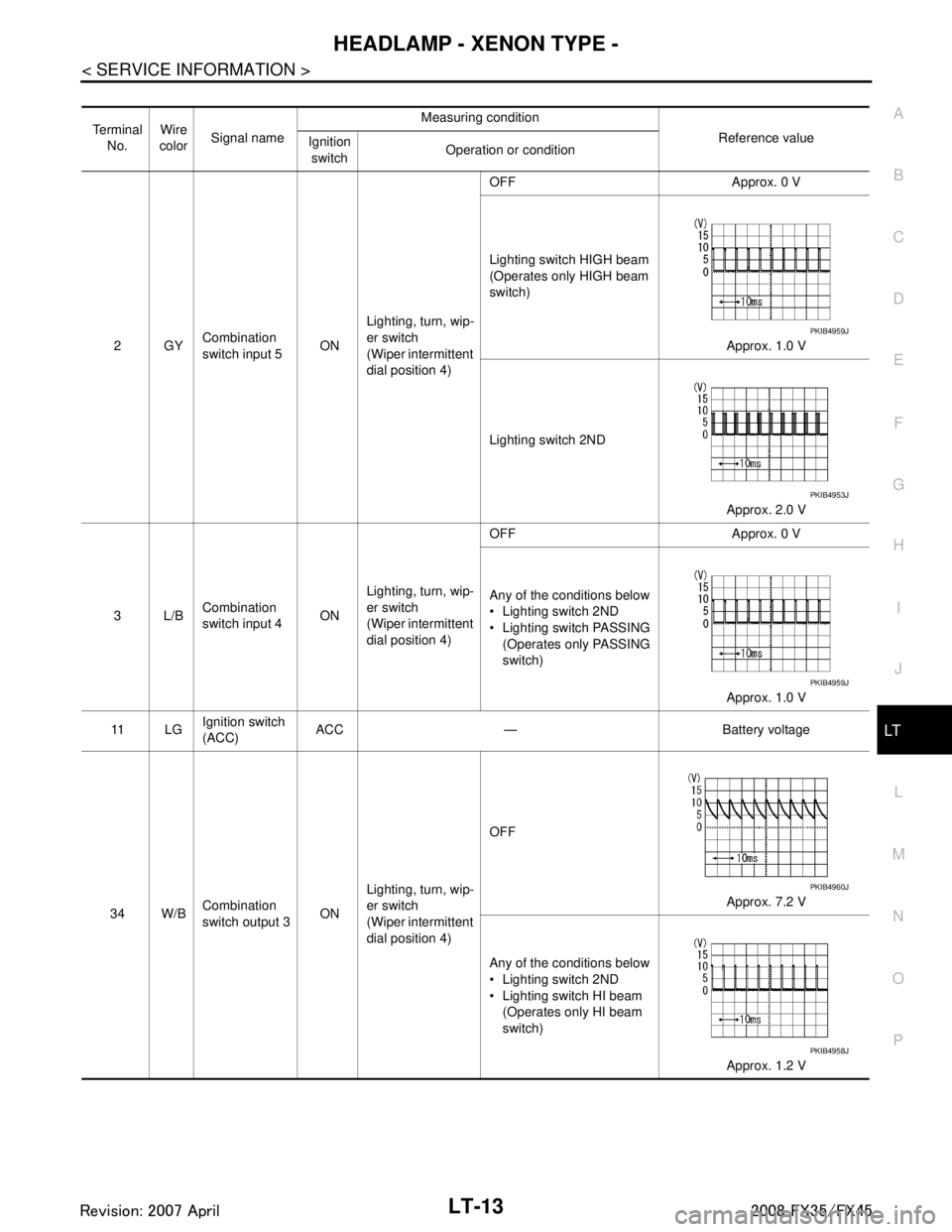
Terminal and Reference Value for BCM
INFOID:0000000001328271
CAUTION:
Check combination switch system terminal waveform under the loaded condition with lighting
switch, turn signal switch and wiper switch OFF not to be fluctuated by overloaded.
Turn wiper intermittent dial posi tion to 4 except when checking wavef orm or voltage of wiper inter-
mittent dial position. Wiper intermittent dial position can be confirmed on CONSULT-III. Refer to LT-
103, "CONSULT-III Functions (BCM)".
TKWM4292E
3AA93ABC3ACD3AC03ACA3AC03AC63AC53A913A773A893A873A873A8E3A773A983AC73AC93AC03AC3
3A893A873A873A8F3A773A9D3AAF3A8A3A8C3A863A9D3AAF3A8B3A8C
Page 3115 of 3924

HEADLAMP - XENON TYPE -LT-13
< SERVICE INFORMATION >
C
DE
F
G H
I
J
L
M A
B
LT
N
O P
Te r m i n a l No. Wire
color Signal name Measuring condition
Reference value
Ignition
switch Operation or condition
2GY Combination
switch input 5 ONLighting, turn, wip-
er switch
(Wiper intermittent
dial position 4) OFF Approx. 0 V
Lighting switch HIGH beam
(Operates only HIGH beam
switch)
Approx. 1.0 V
Lighting switch 2ND Approx. 2.0 V
3L/B Combination
switch input 4 ONLighting, turn, wip-
er switch
(Wiper intermittent
dial position 4) OFF Approx. 0 V
Any of the conditions below
Lighting switch 2ND
Lighting switch PASSING
(Operates only PASSING
switch)
Approx. 1.0 V
11 L G Ignition switch
(ACC) ACC — Battery voltage
34 W/B Combination
switch output 3 ONLighting, turn, wip-
er switch
(Wiper intermittent
dial position 4) OFF
Approx. 7.2 V
Any of the conditions below
Lighting switch 2ND
Lighting switch HI beam (Operates only HI beam
switch)
Approx. 1.2 V
PKIB4959J
PKIB4953J
PKIB4959J
PKIB4960J
PKIB4958J
3AA93ABC3ACD3AC03ACA3AC03AC63AC53A913A773A893A873A873A8E3A773A983AC73AC93AC03AC3
3A893A873A873A8F3A773A9D3AAF3A8A3A8C3A863A9D3AAF3A8B3A8C
Page 3116 of 3924

LT-14
< SERVICE INFORMATION >
HEADLAMP - XENON TYPE -
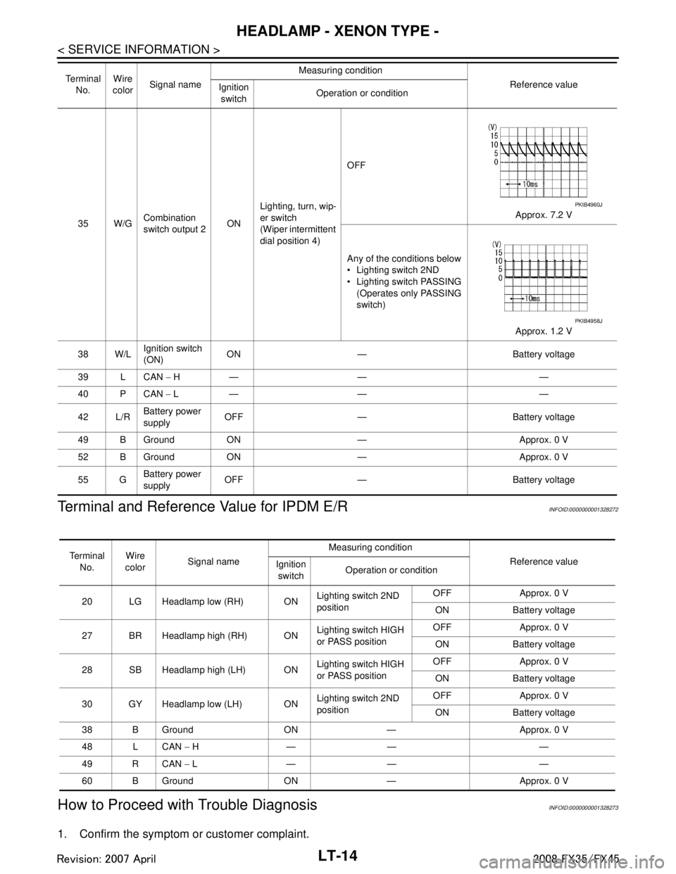
Terminal and Reference Value for IPDM E/R
INFOID:0000000001328272
How to Proceed with Trouble DiagnosisINFOID:0000000001328273
1. Confirm the symptom or customer complaint.
35 W/G Combination
switch output 2 ONLighting, turn, wip-
er switch
(Wiper intermittent
dial position 4) OFF
Approx. 7.2 V
Any of the conditions below
Lighting switch 2ND
Lighting switch PASSING (Operates only PASSING
switch)
Approx. 1.2 V
38 W/L Ignition switch
(ON)
ON — Battery voltage
39 L CAN − H— — —
40 P CAN − L— — —
42 L/R Battery power
supply
OFF — Battery voltage
49 B Ground ON — Approx. 0 V
52 B Ground ON — Approx. 0 V
55 G Battery power
supply OFF — Battery voltage
Te r m i n a l
No. Wire
color Signal name Measuring condition
Reference value
Ignition
switch Operation or condition
PKIB4960J
PKIB4958J
Te r m i n a l
No. Wire
color Signal name Measuring condition
Reference value
Ignition
switch Operation or condition
20 LG Headlamp low (RH) ON Lighting switch 2ND
positionOFF Approx. 0 V
ON Battery voltage
27 BR Headlamp high (RH) ON Lighting switch HIGH
or PASS positionOFF Approx. 0 V
ON Battery voltage
28 SB Headlamp high (LH) ON Lighting switch HIGH
or PASS positionOFF Approx. 0 V
ON Battery voltage
30 GY Headlamp low (LH) ON Lighting switch 2ND
positionOFF Approx. 0 V
ON Battery voltage
38 B Ground ON — Approx. 0 V
48 L CAN − H— — —
49 R CAN − L— — —
60 B Ground ON — Approx. 0 V
3AA93ABC3ACD3AC03ACA3AC03AC63AC53A913A773A893A873A873A8E3A773A983AC73AC93AC03AC3
3A893A873A873A8F3A773A9D3AAF3A8A3A8C3A863A9D3AAF3A8B3A8C
Page 3117 of 3924

HEADLAMP - XENON TYPE -LT-15
< SERVICE INFORMATION >
C
DE
F
G H
I
J
L
M A
B
LT
N
O P
2. Understand operation description and function description. Refer to LT- 5 , "System Description".
3. Perform Preliminary Check. Refer to LT-15, "
Preliminary Check".
4. Check symptom and repair or replace the cause of malfunction.
5. Does headlamp operate normally? If YES, GO TO 6. If NO, GO TO 4.
6. INSPECTION END
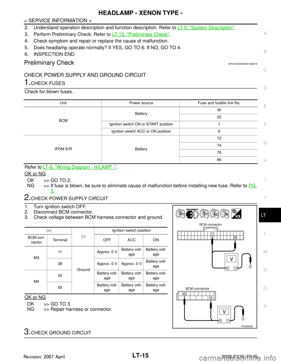
Preliminary CheckINFOID:0000000001328274
CHECK POWER SUPPLY AND GROUND CIRCUIT
1.CHECK FUSES
Check for blown fuses.
Refer to LT- 9 , "
Wiring Diagram - H/LAMP -".
OK or NG
OK >> GO TO 2.
NG >> If fuse is blown, be sure to eliminate caus e of malfunction before installing new fuse. Refer to PG-
3.
2.CHECK POWER SUPPLY CIRCUIT
1. Turn ignition switch OFF.
2. Disconnect BCM connector.
3. Check voltage between BCM harness connector and ground.
OK or NG
OK >> GO TO 3.
NG >> Repair harness or connector.
3.CHECK GROUND CIRCUIT
Unit Power source Fuse and fusible link No.
BCM Battery
M
22
Ignition switch ON or START position 1 Ignition switch ACC or ON position 6
IPDM E/R Battery 72
74
76
86
(+)
(-)Ignition switch position
BCM con- nector Terminal OFF ACC ON
M3 11
Ground Approx. 0 V
Battery volt-
age Battery volt-
age
38 Approx. 0 V Approx. 0 V Battery volt-
age
M4 42
Battery volt-
age Battery volt-
age Battery volt-
age
55 Battery volt-
age Battery volt-
age Battery volt-
age
PKIA5204E
3AA93ABC3ACD3AC03ACA3AC03AC63AC53A913A773A893A873A873A8E3A773A983AC73AC93AC03AC3
3A893A873A873A8F3A773A9D3AAF3A8A3A8C3A863A9D3AAF3A8B3A8C