Page 3826 of 3924
TF-40
< SERVICE INFORMATION >
TRANSFER ASSEMBLY
TRANSFER ASSEMBLY
Removal and InstallationINFOID:0000000001327460
REMOVAL
1. Remove tunnel stay with power tool. Refer to RSU-6, "Removal and Installation".
2. Remove exhaust front tube with power tool. Refer to EX-3
.
3. Remove front and rear propeller shaft. Refer to PR-4
and PR-7.
4. Disconnect transfer assembly harness connector and separate harness from transfer assembly.
5. Remove air breather hose. Refer to TF-39
.
6. Support transfer assembly and transmission assembly with a jack.
7. Remove engine rear member with power tool. Refer to EM-112
(VQ35DE) or EM-237 (VK45DE).
8. Remove transfer mounting bolts and se parate transfer from transmission.
CAUTION:
Secure transfer assembly to a jack.
INSTALLATION
Note the following, and install in the reverse order of removal.
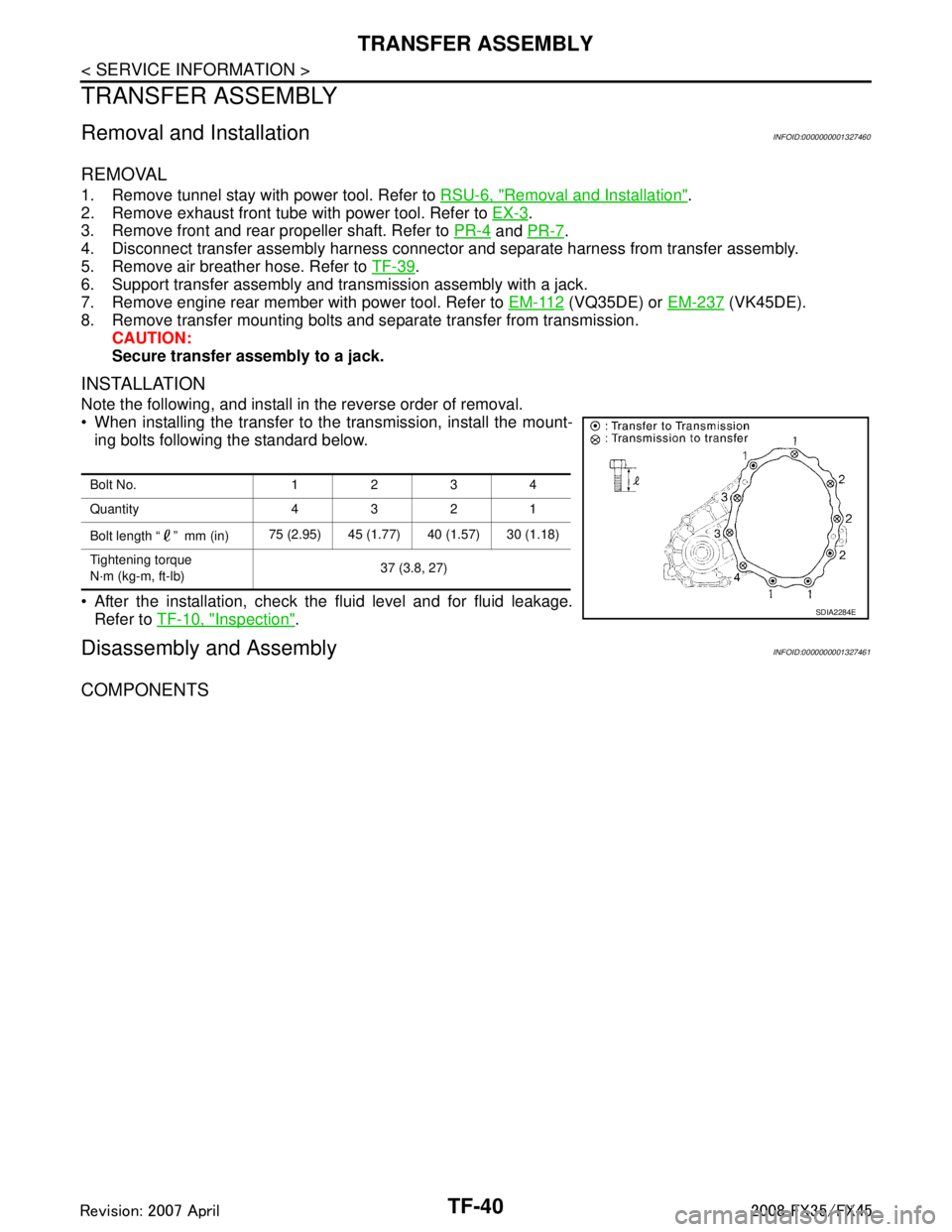
When installing the transfer to the transmission, install the mount-
ing bolts following the standard below.
After the installation, check the fluid level and for fluid leakage. Refer to TF-10, "
Inspection".
Disassembly and AssemblyINFOID:0000000001327461
COMPONENTS
Bolt No. 1234
Quantity 4321
Bolt length “ ” mm (in) 75 (2.95) 45 (1.77) 40 (1.57) 30 (1.18)
Tightening torque
N·m (kg-m, ft-lb) 37 (3.8, 27)
SDIA2284E
3AA93ABC3ACD3AC03ACA3AC03AC63AC53A913A773A893A873A873A8E3A773A983AC73AC93AC03AC3
3A893A873A873A8F3A773A9D3AAF3A8A3A8C3A863A9D3AAF3A8B3A8C
Page 3835 of 3924
TRANSFER ASSEMBLYTF-49
< SERVICE INFORMATION >
CEF
G H
I
J
K L
M A
B
TF
N
O P
4. Install snap ring to mainshaft. CAUTION:
Do not reuse snap ring.
5. Install mainshaft assembly to rear case, then install front case and rear case. Refer to "Front case and rear case".
Front Case and Rear Case
1. Install breather tube, with plastic hammer.CAUTION:
Pay attention to the dir ection of breather tube.
2. Install baffle plate to rear case, and tighten bolt to the specified torque. Refer to "COMPONENTS".
3. Install rear bearing to rear case, using a drift. CAUTION:
Apply ATF to inside of rear bearing.
4. Install snap ring to rear case. CAUTION:
Do not reuse snap ring.
SDIA1602E
PDIA0274E
Tool number : KV38104010 ( — )
PDIA0275E
PDIA0263E
3AA93ABC3ACD3AC03ACA3AC03AC63AC53A913A773A893A873A873A8E3A773A983AC73AC93AC03AC3
3A893A873A873A8F3A773A9D3AAF3A8A3A8C3A863A9D3AAF3A8B3A8C
Page 3836 of 3924
TF-50
< SERVICE INFORMATION >
TRANSFER ASSEMBLY
5. Install mainshaft assembly to rear case, using a drift.CAUTION:
ATF should be applied to contact surface of mainshaft and
rear bearing.
6. Install O-ring to transfer assembly harness connector. CAUTION:
Do not reuse O-ring.
Apply ATF to O-ring.
7. Install transfer assembly harness connector into rear case.
8. Install retainer to transfer assembly harness connector.
9. Hold electric controlled coupling harness (1) with oil cover hold plate (2), install oil cover (3) to rear case (4), and tighten bolt to
the specified torque. Refer to "COMPONENTS".
CAUTION:
The harness should be gu ided by a cut portion.
10. Install oil gutter to rear case. CAUTION:
The tip of oil gutter should be put into rear case groove.Tool number : ST35321000 ( — )
SDIA2368E
SDIA1597E
SDIA3610E
PDIA0261E
3AA93ABC3ACD3AC03ACA3AC03AC63AC53A913A773A893A873A873A8E3A773A983AC73AC93AC03AC3
3A893A873A873A8F3A773A9D3AAF3A8A3A8C3A863A9D3AAF3A8B3A8C
Page 3838 of 3924
TF-52
< SERVICE INFORMATION >
TRANSFER ASSEMBLY
16. Set front case to rear case.CAUTION:
Be careful not to damage th e mating surface transmission
side.
17. Tighten front case and rear case fixing bolts to the specified torque. Refer to "COMPONENTS".
18. Install spacer to mainshaft. CAUTION:
Apply ATF to spacer.
19. Install rear oil seal to rear case, using a drift. CAUTION:
Do not reuse rear oil seal.
Apply ATF to rear oil seal.
When installing, do not incline rear oil seal.
PDIA0279E
Bolts symbol Quantity Bolt length “ ” mm (in)
A 11 42 (1.65)
B 1 162 (6.38)
C197 (3.82)
TORX bolts 1 40 (1.57)
PDIA0251E
PDIA0260E
Dimension A : 6.7 - 7.3 mm (0.264 - 0.287 in)
Tool number A: ST30720000 (J-25405) B: KV40104830 ( — )
PDIA0281E
3AA93ABC3ACD3AC03ACA3AC03AC63AC53A913A773A893A873A873A8E3A773A983AC73AC93AC03AC3
3A893A873A873A8F3A773A9D3AAF3A8A3A8C3A863A9D3AAF3A8B3A8C
Page 3839 of 3924
TRANSFER ASSEMBLYTF-53
< SERVICE INFORMATION >
CEF
G H
I
J
K L
M A
B
TF
N
O P
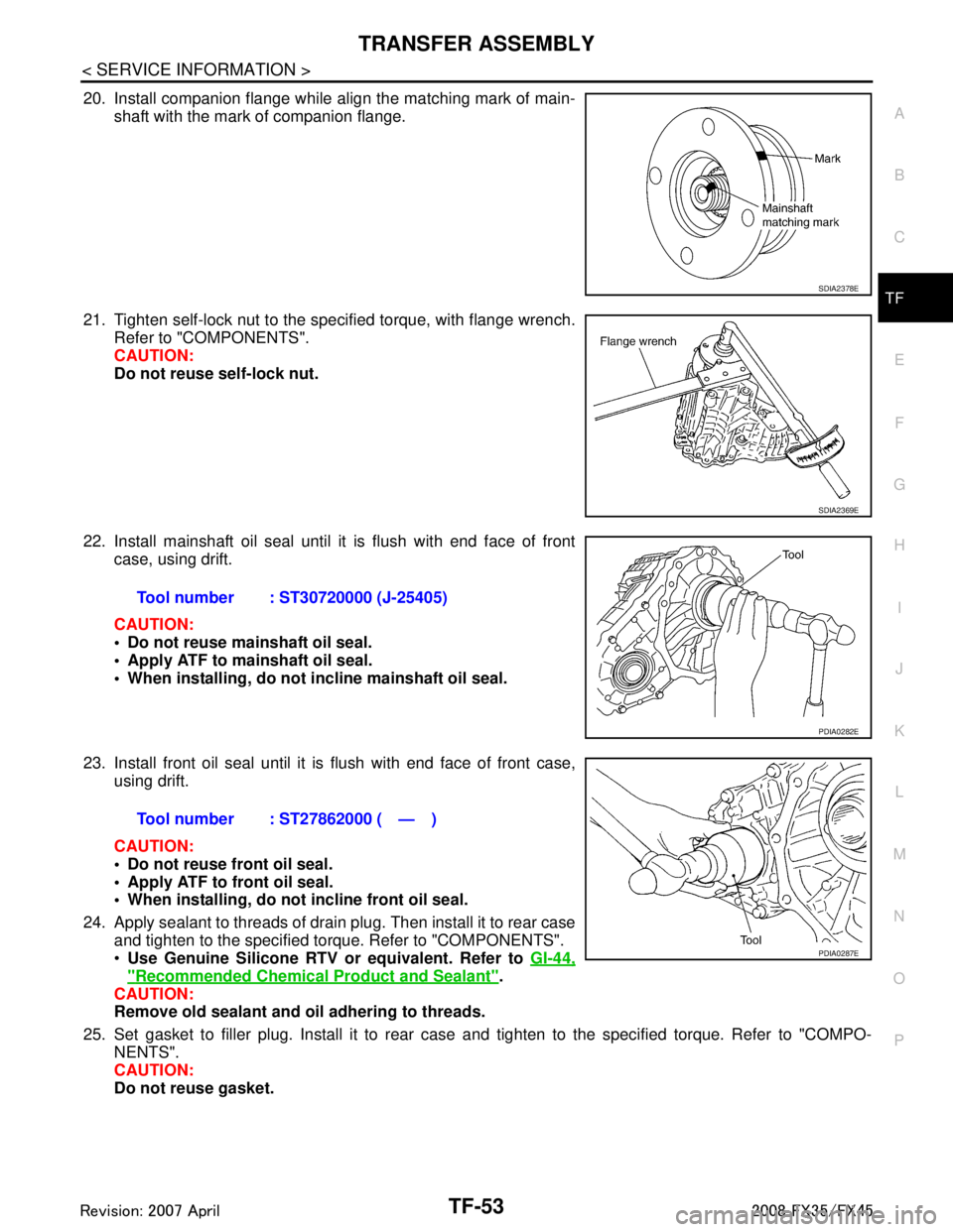
20. Install companion flange while align the matching mark of main- shaft with the mark of companion flange.
21. Tighten self-lock nut to the specified torque, with flange wrench. Refer to "COMPONENTS".
CAUTION:
Do not reuse self-lock nut.
22. Install mainshaft oil seal until it is flush with end face of front case, using drift.
CAUTION:
Do not reuse mainshaft oil seal.
Apply ATF to mainshaft oil seal.
When installing, do not in cline mainshaft oil seal.
23. Install front oil seal until it is flush with end face of front case, using drift.
CAUTION:
Do not reuse front oil seal.
Apply ATF to front oil seal.
When installing, do not incline front oil seal.
24. Apply sealant to threads of drain plug. Then install it to rear case and tighten to the specified torque. Refer to "COMPONENTS".
Use Genuine Silicone RTV or equivalent. Refer to GI-44,
"Recommended Chemical Product and Sealant".
CAUTION:
Remove old sealant and oil adhering to threads.
25. Set gasket to filler plug. Install it to rear case and tighten to the specified torque. Refer to "COMPO-
NENTS".
CAUTION:
Do not reuse gasket.
SDIA2378E
SDIA2369E
Tool number : ST30720000 (J-25405)
PDIA0282E
Tool number : ST27862000 ( — )
PDIA0287E
3AA93ABC3ACD3AC03ACA3AC03AC63AC53A913A773A893A873A873A8E3A773A983AC73AC93AC03AC3
3A893A873A873A8F3A773A9D3AAF3A8A3A8C3A863A9D3AAF3A8B3A8C
Page 3849 of 3924
ROAD WHEEL TIRE ASSEMBLYWT-9
< SERVICE INFORMATION >
C
DF
G H
I
J
K L
M A
B
WT
N
O P
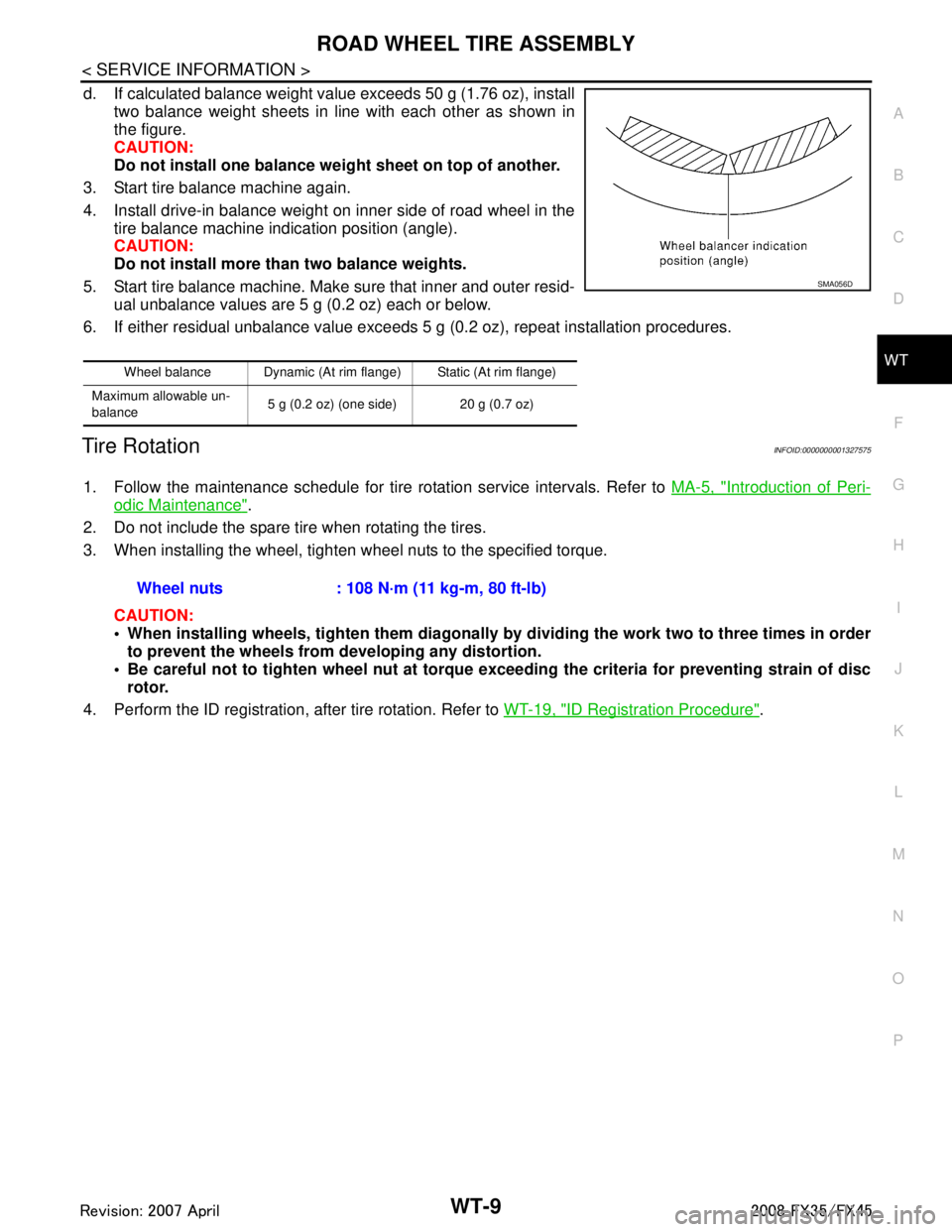
d. If calculated balance weight value exceeds 50 g (1.76 oz), install two balance weight sheets in line with each other as shown in
the figure.
CAUTION:
Do not install one balance weig ht sheet on top of another.
3. Start tire balance machine again.
4. Install drive-in balance weight on inner side of road wheel in the tire balance machine indication position (angle).
CAUTION:
Do not install more than two balance weights.
5. Start tire balance machine. Make sure that inner and outer resid- ual unbalance values are 5 g (0.2 oz) each or below.
6. If either residual unbalance value exceeds 5 g (0.2 oz), repeat installation procedures.
Tire RotationINFOID:0000000001327575
1. Follow the maintenance schedule for tire rotation service intervals. Refer to MA-5, "Introduction of Peri-
odic Maintenance".
2. Do not include the spare tire when rotating the tires.
3. When installing the wheel, tighten wheel nuts to the specified torque.
CAUTION:
When installing wheels, tighten th em diagonally by dividing the work two to three times in order
to prevent the wheels from developing any distortion.
Be careful not to tighten wheel nut at torque exceeding the criteria for preventing strain of disc
rotor.
4. Perform the ID registration, after tire rotation. Refer to WT-19, "
ID Registration Procedure".
Wheel balance Dynamic (At rim flange) Static (At rim flange)
Maximum allowable un-
balance 5 g (0.2 oz) (one side) 20 g (0.7 oz)
SMA056D
Wheel nuts : 108 N·m (11 kg-m, 80 ft-lb)
3AA93ABC3ACD3AC03ACA3AC03AC63AC53A913A773A893A873A873A8E3A773A983AC73AC93AC03AC3
3A893A873A873A8F3A773A9D3AAF3A8A3A8C3A863A9D3AAF3A8B3A8C
Page 3899 of 3924
WW-24
< SERVICE INFORMATION >
FRONT WIPER AND WASHER SYSTEM
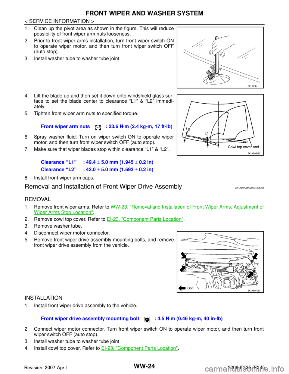
1. Clean up the pivot area as shown in the figure. This will reducepossibility of front wiper arm nuts looseness.
2. Prior to front wiper arms installation, turn front wiper switch ON to operate wiper motor, and then turn front wiper switch OFF
(auto stop).
3. Install washer tube to washer tube joint.
4. Lift the blade up and then set it down onto windshield glass sur- face to set the blade center to clearance “L1” & “L2” immedi-
ately.
5. Tighten front wiper arm nuts to specified torque.
6. Spray washer fluid. Turn on wiper switch ON to operate wiper motor, and then turn front wiper switch OFF (auto stop).
7. Make sure that wiper blades stop within clearance “L1” & “L2”.
8. Install front wiper arm caps.
Removal and Installation of Front Wiper Drive AssemblyINFOID:0000000001328565
REMOVAL
1. Remove front wiper arms. Refer to WW-23, "Removal and Installation of Front Wiper Arms, Adjustment of
Wiper Arms Stop Location".
2. Remove cowl top cover. Refer to EI-23, "
Component Parts Location".
3. Remove washer tube.
4. Disconnect wiper motor connector.
5. Remove front wiper drive assembly mounting bolts, and remove front wiper drive assembly from the vehicle.
INSTALLATION
1. Install front wiper drive assembly to the vehicle.
2. Connect wiper motor connector. Turn front wiper switch ON to operate wiper motor, and then turn frontwiper switch OFF (auto stop).
3. Install washer tube to washer tube joint.
4. Install cowl top cover. Refer to EI-23, "
Component Parts Location".
SEL024J
Front wiper arm nuts : 23.6 N·m (2.4 kg-m, 17 ft-lb)
Clearance “L1” : 49.4 ± 5.0 mm (1.945 ± 0.2 in)
Clearance “L2” : 43.0 ± 5.0 mm (1.693 ± 0.2 in)
PKIA9951E
SKIA5070E
Front wiper drive assembly mounting bo lt : 4.5 N·m (0.46 kg-m, 40 in-lb)
3AA93ABC3ACD3AC03ACA3AC03AC63AC53A913A773A893A873A873A8E3A773A983AC73AC93AC03AC3
3A893A873A873A8F3A773A9D3AAF3A8A3A8C3A863A9D3AAF3A8B3A8C
Page 3916 of 3924
REAR WIPER AND WASHER SYSTEMWW-41
< SERVICE INFORMATION >
C
DE
F
G H
I
J
L
M A
B
WW
N
O P
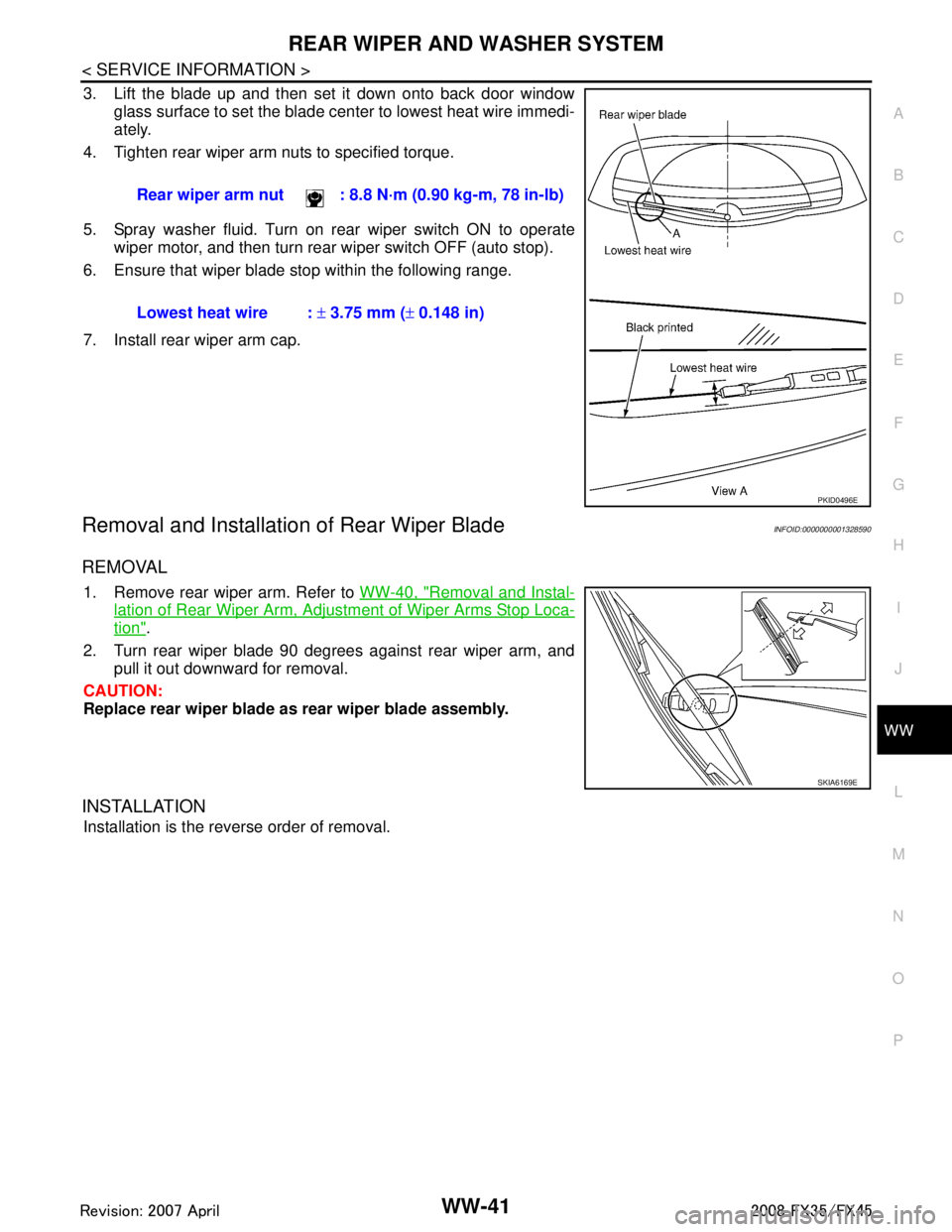
3. Lift the blade up and then set it down onto back door window glass surface to set the blade center to lowest heat wire immedi-
ately.
4. Tighten rear wiper arm nuts to specified torque.
5. Spray washer fluid. Turn on rear wiper switch ON to operate wiper motor, and then turn rear wiper switch OFF (auto stop).
6. Ensure that wiper blade stop within the following range.
7. Install rear wiper arm cap.
Removal and Installation of Rear Wiper BladeINFOID:0000000001328590
REMOVAL
1. Remove rear wiper arm. Refer to WW-40, "Removal and Instal-
lation of Rear Wiper Arm, Adjustment of Wiper Arms Stop Loca-
tion".
2. Turn rear wiper blade 90 degrees against rear wiper arm, and pull it out downward for removal.
CAUTION:
Replace rear wiper blade as rear wiper blade assembly.
INSTALLATION
Installation is the reverse order of removal. Rear wiper arm nut : 8.8 N·m (0.90 kg-m, 78 in-lb)
Lowest heat wire :
± 3.75 mm ( ± 0.148 in)
PKID0496E
SKIA6169E
3AA93ABC3ACD3AC03ACA3AC03AC63AC53A913A773A893A873A873A8E3A773A983AC73AC93AC03AC3
3A893A873A873A8F3A773A9D3AAF3A8A3A8C3A863A9D3AAF3A8B3A8C