2008 INFINITI FX35 gas type
[x] Cancel search: gas typePage 2669 of 3924
![INFINITI FX35 2008 Service Manual
OIL PAN AND OIL STRAINEREM-185
< SERVICE INFORMATION > [VK45DE]
C
D
E
F
G H
I
J
K L
M A
EM
NP
O
Hold pipes and pull them out to front drive shaft (left) installing side.
21. Remove oil strainer.
IN INFINITI FX35 2008 Service Manual
OIL PAN AND OIL STRAINEREM-185
< SERVICE INFORMATION > [VK45DE]
C
D
E
F
G H
I
J
K L
M A
EM
NP
O
Hold pipes and pull them out to front drive shaft (left) installing side.
21. Remove oil strainer.
IN](/manual-img/42/57017/w960_57017-2668.png)
OIL PAN AND OIL STRAINEREM-185
< SERVICE INFORMATION > [VK45DE]
C
D
E
F
G H
I
J
K L
M A
EM
NP
O
Hold pipes and pull them out to front drive shaft (left) installing side.
21. Remove oil strainer.
INSPECTION AFTER REMOVAL
Clean oil strainer if any object attached.
INSTALLATION
1. Install oil strainer.
2. Install axle pipe to oil pan, if removed. Lubricate O-ring groove of axle pipe, O-ring, and O-ring joint ofoil pan with new engine oil.
Right/left O-ring diameters differ from each other. O-ring with
identification paint mark is installed on front drive shaft (left)
installing side.
Install axle pipe to oil pan from (left) side.
CAUTION:
Insert it with care to prevent O-ring from sliding.
3. Install oil pan as follows:
a. Use scraper to remove old liquid gasket from mating surfaces. Also remove the old liquid gasket from mating surface of cylinder block.
Remove old liquid gasket from the bolt holes and threads.
CAUTION:
Do not scratch or damage the mating su rfaces when cleaning off old liquid gasket.
b. Install new O-rings to oil pump and front cover side.
c. Apply a continuous bead of liquid gasket with tube presser (commercial service tool) to the cylinder block mating surfaces
of oil pan to a limited portion as shown in the figure.
Use Genuine RTV Silicone Seal ant or equivalent. Refer to
GI-44, "
Recommended Chemical Product and Sealant".
CAUTION:
Attaching should be done wi thin 5 minutes after coating.
d. Install oil pan. CAUTION:
Install avoiding misal ignment of O-rings.
Tighten mounting bolts in numerical order as shown in the fig- ure.
NOTE:
Tighten mounting bolts No. 1 and 2 in two steps. The numeri-
cal order No. 11 and 17 shown second steps.
There are three types of mounting bolts. Refer to the following for locating bolts.
e. Tighten transmission joint bolts. Refer to AT-243, "
Removal and Installation (AWD Models)".
f. Install rear plate cover.
4. Install oil pan drain plug with new drain plug washer.
PBIC2336E
PBIC0195E
M6 × 30 mm (1.18 in) : 18, 19
M8 × 100 mm (3.94 in) : 5, 9
M8 × 45 mm (1.77 in) : Except the above
PBIC0194E
3AA93ABC3ACD3AC03ACA3AC03AC63AC53A913A773A893A873A873A8E3A773A983AC73AC93AC03AC3
3A893A873A873A8F3A773A9D3AAF3A8A3A8C3A863A9D3AAF3A8B3A8C
Page 2692 of 3924
![INFINITI FX35 2008 Service Manual
EM-208
< SERVICE INFORMATION >[VK45DE]
TIMING CHAIN
b. Apply a continuous bead of liquid gasket with tube presser
(commercial service tool) to front cover as shown in the figure.
Use Genuine RTV Sili INFINITI FX35 2008 Service Manual
EM-208
< SERVICE INFORMATION >[VK45DE]
TIMING CHAIN
b. Apply a continuous bead of liquid gasket with tube presser
(commercial service tool) to front cover as shown in the figure.
Use Genuine RTV Sili](/manual-img/42/57017/w960_57017-2691.png)
EM-208
< SERVICE INFORMATION >[VK45DE]
TIMING CHAIN
b. Apply a continuous bead of liquid gasket with tube presser
(commercial service tool) to front cover as shown in the figure.
Use Genuine RTV Silicone Seal ant or equivalent. Refer to
GI-44, "
Recommended Chemical Product and Sealant".
c. make sure again that the mating marks on timing chain and that on each sprocket are aligned. Then, install front cover.
CAUTION:
Be careful to avoid interferen ce with the front end of oil
pump drive spacer. Such interf erence may damage front oil
seal.
d. Tighten mounting bolts in numerical order as shown in the fig- ure.
There are four type mounting bolts.
e. After all mounting bolts are tightened, retighten t hem in numerical order as shown in the figure.
CAUTION:
Be sure to wipe off any excessive liquid gasket leaking onto surface mating with oil pan.
11. Install intake valve timing control cover as follows:
a. At the back of intake valve timing control cover, in stall new seal rings (three for each bank) to the area to
be inserted into camshaft sprocket (INT).
CAUTION:
Do not spread seal ring excessively to avoid breaks and deformation.
b. Install new O-rings on front cover.
PBIC0062E
KBIA0354J
PBIC1681E
SBIA0374E
3AA93ABC3ACD3AC03ACA3AC03AC63AC53A913A773A893A873A873A8E3A773A983AC73AC93AC03AC3
3A893A873A873A8F3A773A9D3AAF3A8A3A8C3A863A9D3AAF3A8B3A8C
Page 2729 of 3924
![INFINITI FX35 2008 Service Manual
CYLINDER BLOCKEM-245
< SERVICE INFORMATION > [VK45DE]
C
D
E
F
G H
I
J
K L
M A
EM
NP
O
Before loosening main bearing cap bolts, measure the crankshaft end play. Refer to
EM-256, "Inspec-
tion After INFINITI FX35 2008 Service Manual
CYLINDER BLOCKEM-245
< SERVICE INFORMATION > [VK45DE]
C
D
E
F
G H
I
J
K L
M A
EM
NP
O
Before loosening main bearing cap bolts, measure the crankshaft end play. Refer to
EM-256, "Inspec-
tion After](/manual-img/42/57017/w960_57017-2728.png)
CYLINDER BLOCKEM-245
< SERVICE INFORMATION > [VK45DE]
C
D
E
F
G H
I
J
K L
M A
EM
NP
O
Before loosening main bearing cap bolts, measure the crankshaft end play. Refer to
EM-256, "Inspec-
tion After Disassembly".
Loosen main bearing cap bolts in several different steps.
a. Remove cover attached to the rear left side of cylinder block (next to the starter motor housing).
NOTE:
Bolts (No. 27 shown in the figure) are installed on the inside of
cover.
b. Loosen side bolts (M10) starting from 30 to 21 to remove.
c. Loosen main bearing cap sub bolts (M9) starting from 20 to 11 to remove.
d. Loosen main bearing cap bolts (M12) starting from 10 to 1 to remove.
e. Using main bearing cap remover (SST), remove main bearing cap.
15. Remove crankshaft.
16. Remove main bearings and thrust bearings from cylinder block and main bearing caps. CAUTION:
Identify installation po sitions, and store them without mixing them up.
17. If pilot converter must be remov ed, remove it from the rear end
of the crankshaft using pilot bushing puller (SST).
It is possible to remove pilot converter without hoisting engine with engine stand.
ASSEMBLY
1. Fully air-blow engine coolant and engine oil passages in cylinder block, cylinder bore and crankcase to remove any foreign material.
CAUTION:
Use a goggles to protect your eye.
2. Install each plug to the cylinder block. (Only screwed-type plugs are shown in the figure.)
Apply sealant to the thread of each plug “A” and “D”.
Use Genuine High Strength Locking Sealant or equiva-
lent. Refer to GI-44, "
Recommended Chemical Product
and Sealant".
Apply sealant to the thread of each plug “B” and “C”. Use Anaerobic Liquid Gasket or equivalent. Refer to GI-
44, "Recommended Chemical Product and Sealant".
Replace copper washers with new ones.
PBIC0090E
PBIC0091E
PBIC0092E
PBIC1265E
3AA93ABC3ACD3AC03ACA3AC03AC63AC53A913A773A893A873A873A8E3A773A983AC73AC93AC03AC3
3A893A873A873A8F3A773A9D3AAF3A8A3A8C3A863A9D3AAF3A8B3A8C
Page 2916 of 3924

PRECAUTIONSGW-3
< SERVICE INFORMATION >
C
DE
F
G H
J
K L
M A
B
GW
N
O P
SERVICE INFORMATION
PRECAUTIONS
Precaution for Supplemental Restraint System (SRS) "AIR BAG" and "SEAT BELT
PRE-TENSIONER"
INFOID:0000000001612893
The Supplemental Restraint System such as “A IR BAG” and “SEAT BELT PRE-TENSIONER”, used along
with a front seat belt, helps to reduce the risk or severi ty of injury to the driver and front passenger for certain
types of collision. This system includes seat belt switch inputs and dual stage front air bag modules. The SRS
system uses the seat belt switches to determine the front air bag deployment, and may only deploy one front
air bag, depending on the severity of a collision and whether the front occupants are belted or unbelted.
Information necessary to service the system safely is included in the “SUPPLEMENTAL RESTRAINT SYS-
TEM” and “SEAT BELTS” of this Service Manual.
WARNING:
• To avoid rendering the SRS inoper ative, which could increase the risk of personal injury or death in
the event of a collision which would result in air bag inflation, all maintenance must be performed by
an authorized NISSAN/INFINITI dealer.
Improper maintenance, including in correct removal and installation of the SRS, can lead to personal
injury caused by unintentional act ivation of the system. For removal of Spiral Cable and Air Bag
Module, see the “SUPPLEMEN TAL RESTRAINT SYSTEM”.
Do not use electrical test equipm ent on any circuit related to the SRS unless instructed to in this
Service Manual. SRS wiring harnesses can be identi fied by yellow and/or orange harnesses or har-
ness connectors.
Precaution for Procedur e without Cowl Top CoverINFOID:0000000001612894
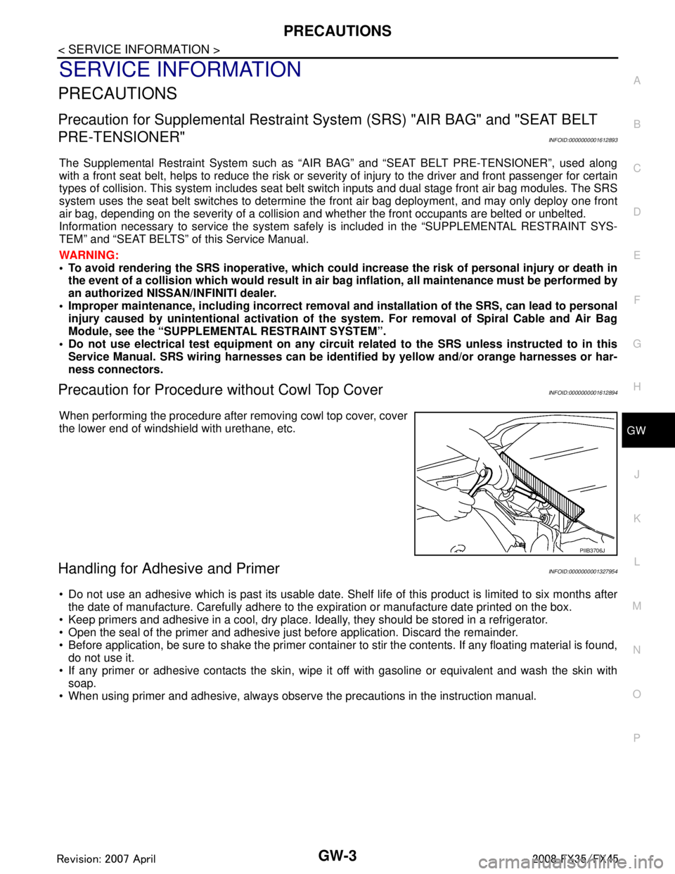
When performing the procedure after removing cowl top cover, cover
the lower end of windshield with urethane, etc.
Handling for Adhesive and PrimerINFOID:0000000001327954
Do not use an adhesive which is past its usable date. Shel f life of this product is limited to six months after
the date of manufacture. Carefully adhere to the ex piration or manufacture date printed on the box.
Keep primers and adhesive in a cool, dry place. I deally, they should be stored in a refrigerator.
Open the seal of the primer and adhesive just before application. Discard the remainder.
Before application, be sure to shake the primer container to stir the contents. If any floating material is found,
do not use it.
If any primer or adhesive contacts the skin, wipe it off with gasoline or equivalent and wash the skin with
soap.
When using primer and adhesive, always observe the precautions in the instruction manual.
PIIB3706J
3AA93ABC3ACD3AC03ACA3AC03AC63AC53A913A773A893A873A873A8E3A773A983AC73AC93AC03AC3
3A893A873A873A8F3A773A9D3AAF3A8A3A8C3A863A9D3AAF3A8B3A8C
Page 3106 of 3924

LT-4
< SERVICE INFORMATION >
PRECAUTIONS
SERVICE INFORMATION
PRECAUTIONS
Precaution for Supplemental Restraint System (SRS) "AIR BAG" and "SEAT BELT
PRE-TENSIONER"
INFOID:0000000001612924
The Supplemental Restraint System such as “A IR BAG” and “SEAT BELT PRE-TENSIONER”, used along
with a front seat belt, helps to reduce the risk or severi ty of injury to the driver and front passenger for certain
types of collision. This system includes seat belt switch inputs and dual stage front air bag modules. The SRS
system uses the seat belt switches to determine the front air bag deployment, and may only deploy one front
air bag, depending on the severity of a collision and w hether the front occupants are belted or unbelted.
Information necessary to service the system safely is included in the “SUPPLEMENTAL RESTRAINT SYS-
TEM” and “SEAT BELTS” of this Service Manual.
WARNING:
• To avoid rendering the SRS inopera tive, which could increase the risk of personal injury or death in
the event of a collision which would result in air bag inflation, all maintenance must be performed by
an authorized NISS AN/INFINITI dealer.
Improper maintenance, including in correct removal and installation of the SRS, can lead to personal
injury caused by unintent ional activation of the system. For re moval of Spiral Cable and Air Bag
Module, see the “SUPPLEMEN TAL RESTRAINT SYSTEM”.
Do not use electrical test equipmen t on any circuit related to the SRS unless instructed to in this
Service Manual. SRS wiring harnesses can be identi fied by yellow and/or orange harnesses or har-
ness connectors.
General Precaution for Service OperationINFOID:0000000001328264
Never work with wet hands.
Xenon headlamp includes high voltage generating part. Be sure to disconnect battery negative cable (negative terminal) or power
fuse before removing, installing, or touching the xenon headlamp
(including lamp bulb).
Turn the lighting switch OFF before disconnecting and connecting the connector.
When turning the xenon headlamp on and while it is illuminated, never touch the harness, bulb, and socket of the headlamp.
When checking the headlamp on/off operation, check it on vehicle
and with the power connected to the vehicle-side connector.
Do not touch the headlamp bulb glass surface with bare hands or allow oil or grease to get on it. Do not touch the headl amp bulb just after the headlamp is turned off, because
it is very hot.
Install the xenon headlamp bulb socket co rrectly. If it is installed improperly, high-voltage leak or corona dis-
charge may occur that can melt the bulb, connecto r, and housing. Do not illuminate the xenon headlamp
bulb out of the headlamp housing. Doing so can cause fire and harm your eyes.
When the bulb has burned out, wrap it in a thick vinyl bag and discard. Do not break the bulb.
Leaving the bulb removed from the headlamp housing for a long period of time can deteriorate the perfor- mance of the lens and reflector (dirt, clouding). Al ways prepare a new bulb and have it on hand when replac-
ing the bulb.
When adjusting the headlamp aiming, turn the aiming adjus tment screw only in the tightening direction. (If it
is necessary to loosen the screw, first fully loosen the screw, and then turn it in the tightening direction.)
Do not use organic solvent (paint thinner or gasoline) to clean lamps and to remove old sealant.
PKID0793E
3AA93ABC3ACD3AC03ACA3AC03AC63AC53A913A773A893A873A873A8E3A773A983AC73AC93AC03AC3
3A893A873A873A8F3A773A9D3AAF3A8A3A8C3A863A9D3AAF3A8B3A8C
Page 3109 of 3924

HEADLAMP - XENON TYPE -LT-7
< SERVICE INFORMATION >
C
DE
F
G H
I
J
L
M A
B
LT
N
O P
Exterior lamp battery saver control mode can be changed by the function setting of CONSULT-III.
AUTO LIGHT OPERATION (IF EQUIPPED)
Refer to LT-47, "System Description".
VEHICLE SECURITY SYSTEM
The vehicle security system will flash the high beams if the system is triggered. Refer to BL-163.
XENON HEADLAMP
Xenon type lamps are used for to the low beam headlamps . Xenon bulbs do not use a filament. Instead, they
produce light when a high voltage current is passed between two tungsten electrodes through a mixture of
xenon (an inert gas) and certain other metal halides. In addition to strong lighting power, electronic control of
the power supply gives the headlamps stable quality and tone color.
Followings are some advantages of the xenon type headlamp.
The light produced by the headlamps is white color si milar to sunlight that is easy to the eyes.
Light output is nearly double that of halogen headl amps, affording increased area of illumination.
Counter-reflected luminance increases and the contrast enhances on the wet road in the rain. That makes
visibility go up more than the increase of the light volume.
Power consumption is approximately 25 percent less than halogen headlamps, reducing battery load.
CAN Communication System DescriptionINFOID:0000000001328267
CAN (Controller Area Network) is a serial communication li ne for real time application. It is an on-vehicle mul-
tiplex communication line with high data communication speed and excellent error detection ability. Many elec-
tronic control units are equipped onto a vehicle, and each control unit shares information and links with other
control units during operation (not independent). In CAN communication, control units are connected with 2
communication lines (CAN H line, CAN L line) allowing a high rate of information transmission with less wiring.
Each control unit transmits/receives data but selectively reads required data only.
CAN Communication UnitINFOID:0000000001328268
Refer to LAN-43, "CAN System Specification Chart".
3AA93ABC3ACD3AC03ACA3AC03AC63AC53A913A773A893A873A873A8E3A773A983AC73AC93AC03AC3
3A893A873A873A8F3A773A9D3AAF3A8A3A8C3A863A9D3AAF3A8B3A8C
Page 3326 of 3924

RECOMMENDED FLUIDS AND LUBRICANTSMA-9
< SERVICE INFORMATION >
C
DE
F
G H
I
J
K
M A
B
MA
N
O P
RECOMMENDED FLUIDS AND LUBRICANTS
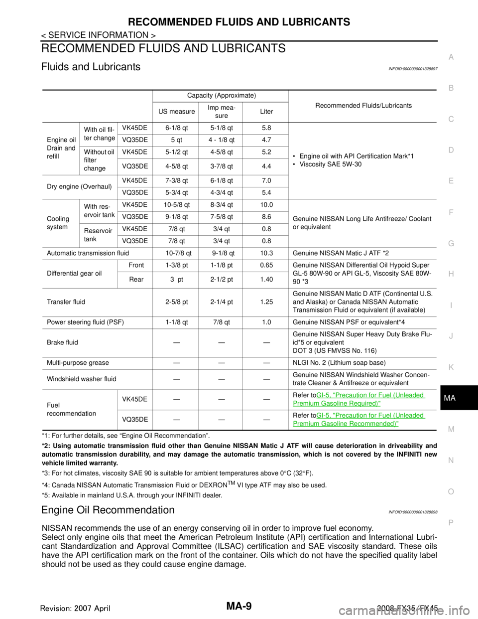
Fluids and LubricantsINFOID:0000000001328897
*1: For further details, see “Engine Oil Recommendation”.
*2: Using automatic transmission fluid other than Genuine NISSAN Matic J ATF will cause deterioration in driveability and
automatic transmission durability, and may damage the automatic transmission, which is not covered by the INFINITI new
vehicle limited warranty.
*3: For hot climates, viscosity SAE 90 is suitable for ambient temperatures above 0 °C (32 °F).
*4: Canada NISSAN Au tomatic Transmission Fluid or DEXRON
TM VI type ATF may also be used.
*5: Available in mainland U.S.A. through your INFINITI dealer.
Engine Oil RecommendationINFOID:0000000001328898
NISSAN recommends the use of an energy conser ving oil in order to improve fuel economy.
Select only engine oils that meet the American Petroleum Institute (API) certification and International Lubri-
cant Standardization and Approval Committee (ILSAC) certification and SAE viscosity standard. These oils
have the API certification mark on the front of the c ontainer. Oils which do not have the specified quality label
should not be used as they could cause engine damage.
Capacity (Approximate)
Recommended Fluids/Lubricants
US measure Imp mea-
sure Liter
Engine oil
Drain and
refill With oil fil-
ter change
VK45DE 6-1/8 qt 5-1/8 qt 5.8
Engine oil with API Certification Mark*1
Viscosity SAE 5W-30
VQ35DE 5 qt 4 - 1/8 qt 4.7
Without oil
filter
change VK45DE 5-1/2 qt 4-5/8 qt 5.2
VQ35DE 4-5/8 qt 3-7/8 qt 4.4
Dry engine (Overhaul) VK45DE 7-3/8 qt 6-1/8 qt 7.0
VQ35DE 5-3/4 qt 4-3/4 qt 5.4
Cooling
system With res-
ervoir tank
VK45DE 10-5/8 qt 8-3/4 qt 10.0
Genuine NISSAN Long Life Antifreeze/ Coolant
or equivalent
VQ35DE 9-1/8 qt 7-5/8 qt 8.6
Reservoir
tank VK45DE 7/8 qt 3/4 qt 0.8
VQ35DE 7/8 qt 3/4 qt 0.8
Automatic transmission fluid 10-7/8 qt 9-1/8 qt 10.3 Genuine NISSAN Matic J ATF *2
Differential gear oil Front 1-3/8 pt 1-1/8 pt 0.65 Genuine NI
SSAN Differential Oil Hypoid Super
GL-5 80W-90 or API GL-5, Viscosity SAE 80W-
90 *3
Rear 3 pt 2-1/2 pt 1.40
Transfer fluid 2-5/8 pt 2-1/4 pt 1.25 Genuine NISSAN Matic D ATF (Continental U.S.
and Alaska) or Canada NISSAN Automatic
Transmission Fluid or equivalent (if available)
Power steering fluid (PSF) 1-1/8 qt 7/8 qt 1.0 Genuine NISSAN PSF or equivalent*4
Brake fluid — — — Genuine NISSAN Super He
avy Duty Brake Flu-
id*5 or equivalent
DOT 3 (US FMVSS No. 116)
Multi-purpose grease — — — NLGI No. 2 (Lithium soap base)
Windshield washer fluid — — — Genuine NISSAN Windshie
ld Washer Concen-
trate Cleaner & Antifreeze or equivalent
Fuel
recommendation VK45DE — — —
Refer to
GI-5, "
Precaution for Fuel (Unleaded
Premium Gasoline Required)"
VQ35DE——— Refer to
GI-5, "Precaution for Fuel (Unleaded
Premium Gasoline Recommended)"
3AA93ABC3ACD3AC03ACA3AC03AC63AC53A913A773A893A873A873A8E3A773A983AC73AC93AC03AC3
3A893A873A873A8F3A773A9D3AAF3A8A3A8C3A863A9D3AAF3A8B3A8C